
Dual Mode PWM PULSE Square Wave Rectangular Wave Signal Adjustable Generator Control Module DC Stepper Motor Drive Driver Board

Dual Mode PWM PULSE Square Wave Rectangular Wave Signal Adjustable Generator Control Module DC Stepper Motor Drive Driver Board
SKU:X13468- guaranteeQuality checked
- Special gift cardsSpecial gift cards
- Free return Within 60 days
- Consultancy86-0755-85201155

1.PWM signal generator, square wave rectangular wave signal generator
2. Used to generate square wave rectangular wave signals for controlling DC motor or stepper motor driver; used for servo motor, stepping motor, electric gripper, replacing PLC pulse, etc.
3. The supporting driver realizes dimming, speed regulation, control of solenoid valve, etc., but can not directly drive the load of the electric motor solenoid valve.
1. Product Highlights:
1.1 Two modes can be selected:
PWM mode - frequency (continuous), duty cycle, pulse number adjustable;
PULSE pulse mode - positive pulse width time, negative pulse width time, delay start time, and number of pulses are adjustable.
1.2 With start and stop button, can control the output and stop of the signal
1.3 Wide voltage input 3.3-30V, with anti-reverse protection, 5.08mm terminal wiring
2. Technical parameters:
2.1 Working voltage: 3.3~30V, with anti-reverse protection
2.2 Frequency range: 1Hz~150KHz, accuracy about 2%
2.3 duty cycle range: 0-100%, 1% stepping
2.4 number of pulses: 1-9999, or infinite (display ‘----' stands for infinity)
2.5 delay output time: 0.000s-9999s, the minimum can be set 1ms
2.6 positive and negative pulse width length: 0.000s-9999s, the minimum can be set 1ms
2.7 signal loading capacity: less than 30mA
2.8 Output signal amplitude: amplitude is equal to the supply voltage
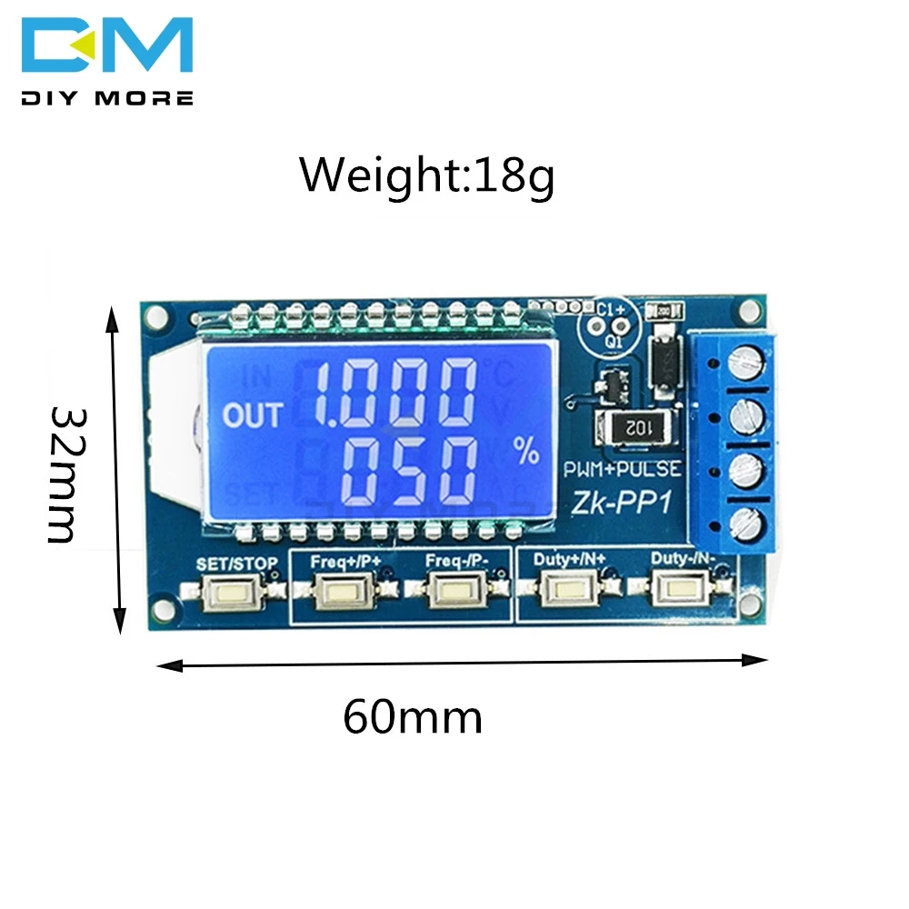
2.9 Product size: 60mm*32mm*10mm
2.10 Product Weight: 18g
2.11 Packing: Anti-static bag
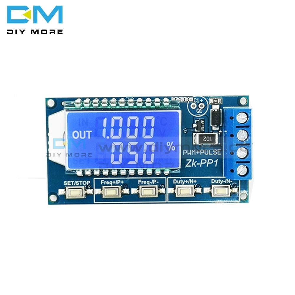
3. PWM mode (display has "%" for PWM mode)
The factory default mode is PWM mode, FREQ+ and FREQ-key set frequency, DUTY+ and DUTY-button set duty cycle; short press STOP button control signal output or stop, stop output is 0, the screen displays “OUT” mark as There is output, otherwise it stops output; the default factory frequency is 1KHZ and the duty cycle is 50%.
If you want to switch to PULSE pulse mode, long press the SET button (more than 6 seconds), do not release, you will see the screen change, "%" disappears, it is PULSE mode.
3.2 PULSE pulse mode (No "%" on the right side of the display is displayed in PULSE mode)
The P+ and P- buttons set the positive pulse width time, the LCD screen shows up, the N+ and N- buttons set the negative pulse width time, the LCD screen displays downwards, the unit is seconds; short press the STOP button to control the signal output or stop, stop output It is 0, the screen displays “OUT” mark as output, otherwise it stops output; the default factory positive pulse width is 0.5 second, and the negative pulse width is 0.5 second.
Pulse number and delay time setting - In PULSE mode, press and hold the SET button for 2 seconds and then release, enter the pulse number and delay time setting interface, the screen displays SET, it will be turned off and cleared after entering. Output pulse; P+ and P- buttons set delay time, N+ and N- buttons set pulse number, factory default delay time is 0 seconds, pulse number is infinite (display ----); Press the button for 2 seconds, automatically return to the pulse interface, press the STOP button, after the delay setting time, start to send the set number of pulses, if the number of pulses is sent, it will automatically output 0, if the period is not sent, press the STOP button. The output pulse will be turned off and cleared, and the number of pulses set will be issued each time it is started.
3.3 Application Operation Examples
3.3.1 PWM output 20KHZ, 60% duty cycle: Select PWM mode, the frequency is set to 20.00, and the duty ratio is set to 060%.
3.3.2 The output is turned on for 0.6 seconds and turned off for 0.2 seconds. Infinite loop: select PULSE mode, the positive pulse width is set to 0.600, the negative pulse width is set to 0.200, the delay time is set to 0.000, and the number of pulses is set to --- -.
3.3.3 Power on or press the start button, delay 5 seconds, then the output is turned on for 0.6 seconds, off 0.2 seconds, infinite loop: select PULSE mode, positive pulse width is set to 0.600, negative pulse width is set to 0.200, delay The time is set to 5.000 and the number of pulses is set to ----.
3.3.4 Power on or press the start button, delay 5 seconds, then output high level 10ms low level 10ms pulse 100: select PULSE mode, positive pulse width is set to 0.010, negative pulse width is set to 0.010, delay The time is set to 5.000 and the number of pulses is set to 0100.
3.3.5 Power-on delay for 10 seconds, then permanently output signal: select PULSE mode, the positive pulse width is set to a number greater than 0, the negative pulse width is set to 0, the delay time is set to 10.00 seconds, and the pulse number is infinite. (----).
3.3.6 Other applications can explore or consult customer service
All setup parameters are not lost when they are turned off.


Purchasing & Delivery
Before you make your purchase, it’s helpful to know the measurements of the area you plan to place the furniture. You should also measure any doorways and hallways through which the furniture will pass to get to its final destination.Picking up at the store
Shopify Shop requires that all products are properly inspected BEFORE you take it home to insure there are no surprises. Our team is happy to open all packages and will assist in the inspection process. We will then reseal packages for safe transport. We encourage all customers to bring furniture pads or blankets to protect the items during transport as well as rope or tie downs. Shopify Shop will not be responsible for damage that occurs after leaving the store or during transit. It is the purchaser’s responsibility to make sure the correct items are picked up and in good condition.Delivery
Customers are able to pick the next available delivery day that best fits their schedule. However, to route stops as efficiently as possible, Shopify Shop will provide the time frame. Customers will not be able to choose a time. You will be notified in advance of your scheduled time frame. Please make sure that a responsible adult (18 years or older) will be home at that time.In preparation for your delivery, please remove existing furniture, pictures, mirrors, accessories, etc. to prevent damages. Also insure that the area where you would like your furniture placed is clear of any old furniture and any other items that may obstruct the passageway of the delivery team. Shopify Shop will deliver, assemble, and set-up your new furniture purchase and remove all packing materials from your home. Our delivery crews are not permitted to move your existing furniture or other household items. Delivery personnel will attempt to deliver the purchased items in a safe and controlled manner but will not attempt to place furniture if they feel it will result in damage to the product or your home. Delivery personnel are unable to remove doors, hoist furniture or carry furniture up more than 3 flights of stairs. An elevator must be available for deliveries to the 4th floor and above.
Other Customers also buy:
-
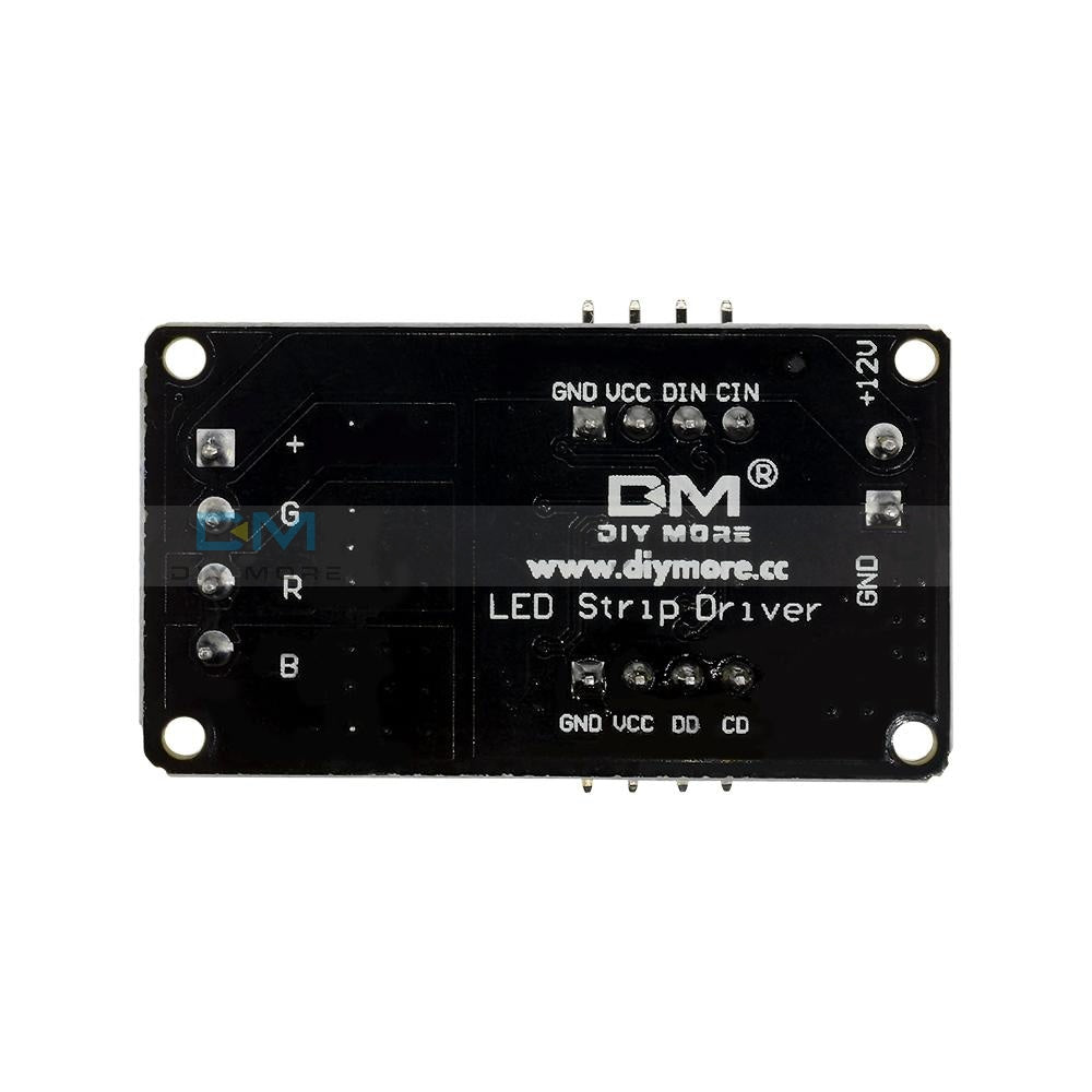
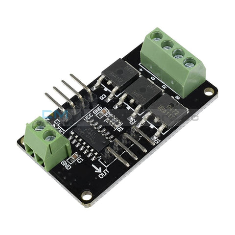 Translation missing: en.products.product.regular_price $5.99{"id":4419937927239,"title":"Dual Mode PWM PULSE Square Wave Rectangular Wave Signal Adjustable Generator Control Module DC Stepper Motor Drive Driver Board","handle":"dual-mode-pwm-pulse-square-wave-rectangular-wave-signal-adjustable-generator-control-module-dc-stepper-motor-drive-driver-board","description":"\u003cdiv\u003e\n\u003cp\u003e\u003cwidget data-widget-type=\"customText\" id=\"33684419\" title=\"Head\" type=\"custom\"\u003e\u003c\/widget\u003e\u003c\/p\u003e\n\u003cp\u003e \u003c\/p\u003e\n\u003cp\u003e\u003cimg src=\"https:\/\/ae01.alicdn.com\/kf\/HTB12JMgilsmBKNjSZFsq6yXSVXaS.jpg\"\u003e\u003c\/p\u003e\n\u003cp\u003e \u003c\/p\u003e\n\u003cp style='box-sizing:content-box;font-size:13px;border-top:0px;font-family:\"Open Sans\", Arial, Helvetica, sans-serif, SimSun, 宋体;border-right:0px;vertical-align:baseline;white-space:normal;word-spacing:0px;border-bottom:0px;text-transform:none;font-weight:400;color:#000000;padding-bottom:0px;font-style:normal;padding-top:0px;padding-left:0px;margin:0px;border-left:0px;orphans:2;widows:2;letter-spacing:normal;padding-right:0px;background-color:#FFFFFF;text-indent:0px;font-variant-ligatures:normal;font-variant-caps:normal;font-variant-numeric:inherit;font-variant-east-asian:inherit;font-stretch:inherit;-webkit-text-stroke-width:0px;text-decoration-style:initial;text-decoration-color:initial;'\u003e\u003cspan style='box-sizing:content-box;font-size:18px;border-top:0px;font-family:\"Trebuchet MS\";border-right:0px;vertical-align:baseline;border-bottom:0px;padding-bottom:0px;padding-top:0px;padding-left:0px;margin:0px;border-left:0px;padding-right:0px;font-stretch:inherit;' data-spm-anchor-id=\"2114.10010108.1000023.i0.70637de6zbrpaz\"\u003e1.PWM signal generator, square wave rectangular wave signal generator\u003c\/span\u003e\u003c\/p\u003e\n\u003cp style='box-sizing:content-box;font-size:13px;border-top:0px;font-family:\"Open Sans\", Arial, Helvetica, sans-serif, SimSun, 宋体;border-right:0px;vertical-align:baseline;white-space:normal;word-spacing:0px;border-bottom:0px;text-transform:none;font-weight:400;color:#000000;padding-bottom:0px;font-style:normal;padding-top:0px;padding-left:0px;margin:0px;border-left:0px;orphans:2;widows:2;letter-spacing:normal;padding-right:0px;background-color:#FFFFFF;text-indent:0px;font-variant-ligatures:normal;font-variant-caps:normal;font-variant-numeric:inherit;font-variant-east-asian:inherit;font-stretch:inherit;-webkit-text-stroke-width:0px;text-decoration-style:initial;text-decoration-color:initial;'\u003e\u003cspan style='box-sizing:content-box;font-size:18px;border-top:0px;font-family:\"Trebuchet MS\";border-right:0px;vertical-align:baseline;border-bottom:0px;padding-bottom:0px;padding-top:0px;padding-left:0px;margin:0px;border-left:0px;padding-right:0px;font-stretch:inherit;'\u003e2. Used to generate square wave rectangular wave signals for controlling DC motor or stepper motor driver; used for servo motor, stepping motor, electric gripper, replacing PLC pulse, etc.\u003c\/span\u003e\u003c\/p\u003e\n\u003cp style='box-sizing:content-box;font-size:13px;border-top:0px;font-family:\"Open Sans\", Arial, Helvetica, sans-serif, SimSun, 宋体;border-right:0px;vertical-align:baseline;white-space:normal;word-spacing:0px;border-bottom:0px;text-transform:none;font-weight:400;color:#000000;padding-bottom:0px;font-style:normal;padding-top:0px;padding-left:0px;margin:0px;border-left:0px;orphans:2;widows:2;letter-spacing:normal;padding-right:0px;background-color:#FFFFFF;text-indent:0px;font-variant-ligatures:normal;font-variant-caps:normal;font-variant-numeric:inherit;font-variant-east-asian:inherit;font-stretch:inherit;-webkit-text-stroke-width:0px;text-decoration-style:initial;text-decoration-color:initial;'\u003e\u003cspan style='box-sizing:content-box;font-size:18px;border-top:0px;font-family:\"Trebuchet MS\";border-right:0px;vertical-align:baseline;border-bottom:0px;padding-bottom:0px;padding-top:0px;padding-left:0px;margin:0px;border-left:0px;padding-right:0px;font-stretch:inherit;'\u003e3. The supporting driver realizes dimming, speed regulation, control of solenoid valve, etc., but can not directly drive the load of the electric motor solenoid valve.\u003c\/span\u003e\u003c\/p\u003e\n\u003cp style='box-sizing:content-box;font-size:13px;border-top:0px;font-family:\"Open Sans\", Arial, Helvetica, sans-serif, SimSun, 宋体;border-right:0px;vertical-align:baseline;white-space:normal;word-spacing:0px;border-bottom:0px;text-transform:none;font-weight:400;color:#000000;padding-bottom:0px;font-style:normal;padding-top:0px;padding-left:0px;margin:0px;border-left:0px;orphans:2;widows:2;letter-spacing:normal;padding-right:0px;background-color:#FFFFFF;text-indent:0px;font-variant-ligatures:normal;font-variant-caps:normal;font-variant-numeric:inherit;font-variant-east-asian:inherit;font-stretch:inherit;-webkit-text-stroke-width:0px;text-decoration-style:initial;text-decoration-color:initial;'\u003e\u003cspan style='box-sizing:content-box;font-size:18px;border-top:0px;font-family:\"Trebuchet MS\";border-right:0px;vertical-align:baseline;border-bottom:0px;padding-bottom:0px;padding-top:0px;padding-left:0px;margin:0px;border-left:0px;padding-right:0px;font-stretch:inherit;'\u003e\u003c\/span\u003e \u003c\/p\u003e\n\u003cp style='box-sizing:content-box;font-size:13px;border-top:0px;font-family:\"Open Sans\", Arial, Helvetica, sans-serif, SimSun, 宋体;border-right:0px;vertical-align:baseline;white-space:normal;word-spacing:0px;border-bottom:0px;text-transform:none;font-weight:400;color:#000000;padding-bottom:0px;font-style:normal;padding-top:0px;padding-left:0px;margin:0px;border-left:0px;orphans:2;widows:2;letter-spacing:normal;padding-right:0px;background-color:#FFFFFF;text-indent:0px;font-variant-ligatures:normal;font-variant-caps:normal;font-variant-numeric:inherit;font-variant-east-asian:inherit;font-stretch:inherit;-webkit-text-stroke-width:0px;text-decoration-style:initial;text-decoration-color:initial;'\u003e\u003cspan style='box-sizing:content-box;font-size:18px;border-top:0px;font-family:\"Trebuchet MS\";border-right:0px;vertical-align:baseline;border-bottom:0px;color:#FF0000;padding-bottom:0px;padding-top:0px;padding-left:0px;margin:0px;border-left:0px;padding-right:0px;font-stretch:inherit;'\u003e1. Product Highlights:\u003c\/span\u003e\u003cbr style=\"box-sizing:content-box;\"\u003e\u003cspan style='box-sizing:content-box;font-size:18px;border-top:0px;font-family:\"Trebuchet MS\";border-right:0px;vertical-align:baseline;border-bottom:0px;padding-bottom:0px;padding-top:0px;padding-left:0px;margin:0px;border-left:0px;padding-right:0px;font-stretch:inherit;'\u003e1.1 Two modes can be selected:\u003c\/span\u003e\u003cbr style=\"box-sizing:content-box;\"\u003e\u003cspan style='box-sizing:content-box;font-size:18px;border-top:0px;font-family:\"Trebuchet MS\";border-right:0px;vertical-align:baseline;border-bottom:0px;padding-bottom:0px;padding-top:0px;padding-left:0px;margin:0px;border-left:0px;padding-right:0px;font-stretch:inherit;'\u003ePWM mode - frequency (continuous), duty cycle, pulse number adjustable;\u003c\/span\u003e\u003cbr style=\"box-sizing:content-box;\"\u003e\u003cspan style='box-sizing:content-box;font-size:18px;border-top:0px;font-family:\"Trebuchet MS\";border-right:0px;vertical-align:baseline;border-bottom:0px;padding-bottom:0px;padding-top:0px;padding-left:0px;margin:0px;border-left:0px;padding-right:0px;font-stretch:inherit;'\u003ePULSE pulse mode - positive pulse width time, negative pulse width time, delay start time, and number of pulses are adjustable.\u003c\/span\u003e\u003cbr style=\"box-sizing:content-box;\"\u003e\u003cspan style='box-sizing:content-box;font-size:18px;border-top:0px;font-family:\"Trebuchet MS\";border-right:0px;vertical-align:baseline;border-bottom:0px;padding-bottom:0px;padding-top:0px;padding-left:0px;margin:0px;border-left:0px;padding-right:0px;font-stretch:inherit;'\u003e1.2 With start and stop button, can control the output and stop of the signal\u003c\/span\u003e\u003cbr style=\"box-sizing:content-box;\"\u003e\u003cspan style='box-sizing:content-box;font-size:18px;border-top:0px;font-family:\"Trebuchet MS\";border-right:0px;vertical-align:baseline;border-bottom:0px;padding-bottom:0px;padding-top:0px;padding-left:0px;margin:0px;border-left:0px;padding-right:0px;font-stretch:inherit;'\u003e1.3 Wide voltage input 3.3-30V, with anti-reverse protection, 5.08mm terminal wiring\u003c\/span\u003e\u003c\/p\u003e\n\u003cp\u003e\u003cbr style='box-sizing:content-box;font-size:13px;font-family:\"Open Sans\", Arial, Helvetica, sans-serif, SimSun, 宋体;white-space:normal;word-spacing:0px;text-transform:none;font-weight:400;color:#000000;font-style:normal;orphans:2;widows:2;letter-spacing:normal;background-color:#FFFFFF;text-indent:0px;font-variant-ligatures:normal;font-variant-caps:normal;-webkit-text-stroke-width:0px;text-decoration-style:initial;text-decoration-color:initial;'\u003e\u003cspan style='box-sizing:content-box;font-size:18px;border-top:0px;font-family:\"Trebuchet MS\";border-right:0px;vertical-align:baseline;white-space:normal;word-spacing:0px;border-bottom:0px;text-transform:none;font-weight:400;color:#FF0000;padding-bottom:0px;font-style:normal;padding-top:0px;padding-left:0px;margin:0px;border-left:0px;orphans:2;widows:2;letter-spacing:normal;padding-right:0px;background-color:#FFFFFF;text-indent:0px;font-variant-ligatures:normal;font-variant-caps:normal;font-variant-numeric:inherit;font-variant-east-asian:inherit;font-stretch:inherit;-webkit-text-stroke-width:0px;text-decoration-style:initial;text-decoration-color:initial;'\u003e2. Technical parameters:\u003c\/span\u003e\u003cbr style='box-sizing:content-box;font-size:13px;font-family:\"Open Sans\", Arial, Helvetica, sans-serif, SimSun, 宋体;white-space:normal;word-spacing:0px;text-transform:none;font-weight:400;color:#000000;font-style:normal;orphans:2;widows:2;letter-spacing:normal;background-color:#FFFFFF;text-indent:0px;font-variant-ligatures:normal;font-variant-caps:normal;-webkit-text-stroke-width:0px;text-decoration-style:initial;text-decoration-color:initial;'\u003e\u003cspan style='box-sizing:content-box;font-size:18px;border-top:0px;font-family:\"Trebuchet MS\";border-right:0px;vertical-align:baseline;white-space:normal;word-spacing:0px;border-bottom:0px;text-transform:none;font-weight:400;color:#000000;padding-bottom:0px;font-style:normal;padding-top:0px;padding-left:0px;margin:0px;border-left:0px;orphans:2;widows:2;letter-spacing:normal;padding-right:0px;background-color:#FFFFFF;text-indent:0px;font-variant-ligatures:normal;font-variant-caps:normal;font-variant-numeric:inherit;font-variant-east-asian:inherit;font-stretch:inherit;-webkit-text-stroke-width:0px;text-decoration-style:initial;text-decoration-color:initial;'\u003e2.1 Working voltage: 3.3~30V, with anti-reverse protection\u003c\/span\u003e\u003cbr style='box-sizing:content-box;font-size:13px;font-family:\"Open Sans\", Arial, Helvetica, sans-serif, SimSun, 宋体;white-space:normal;word-spacing:0px;text-transform:none;font-weight:400;color:#000000;font-style:normal;orphans:2;widows:2;letter-spacing:normal;background-color:#FFFFFF;text-indent:0px;font-variant-ligatures:normal;font-variant-caps:normal;-webkit-text-stroke-width:0px;text-decoration-style:initial;text-decoration-color:initial;'\u003e\u003cspan style='box-sizing:content-box;font-size:18px;border-top:0px;font-family:\"Trebuchet MS\";border-right:0px;vertical-align:baseline;white-space:normal;word-spacing:0px;border-bottom:0px;text-transform:none;font-weight:400;color:#000000;padding-bottom:0px;font-style:normal;padding-top:0px;padding-left:0px;margin:0px;border-left:0px;orphans:2;widows:2;letter-spacing:normal;padding-right:0px;background-color:#FFFFFF;text-indent:0px;font-variant-ligatures:normal;font-variant-caps:normal;font-variant-numeric:inherit;font-variant-east-asian:inherit;font-stretch:inherit;-webkit-text-stroke-width:0px;text-decoration-style:initial;text-decoration-color:initial;'\u003e2.2 Frequency range: 1Hz~150KHz, accuracy about 2%\u003c\/span\u003e\u003cbr style='box-sizing:content-box;font-size:13px;font-family:\"Open Sans\", Arial, Helvetica, sans-serif, SimSun, 宋体;white-space:normal;word-spacing:0px;text-transform:none;font-weight:400;color:#000000;font-style:normal;orphans:2;widows:2;letter-spacing:normal;background-color:#FFFFFF;text-indent:0px;font-variant-ligatures:normal;font-variant-caps:normal;-webkit-text-stroke-width:0px;text-decoration-style:initial;text-decoration-color:initial;'\u003e\u003cspan style='box-sizing:content-box;font-size:18px;border-top:0px;font-family:\"Trebuchet MS\";border-right:0px;vertical-align:baseline;white-space:normal;word-spacing:0px;border-bottom:0px;text-transform:none;font-weight:400;color:#000000;padding-bottom:0px;font-style:normal;padding-top:0px;padding-left:0px;margin:0px;border-left:0px;orphans:2;widows:2;letter-spacing:normal;padding-right:0px;background-color:#FFFFFF;text-indent:0px;font-variant-ligatures:normal;font-variant-caps:normal;font-variant-numeric:inherit;font-variant-east-asian:inherit;font-stretch:inherit;-webkit-text-stroke-width:0px;text-decoration-style:initial;text-decoration-color:initial;'\u003e2.3 duty cycle range: 0-100%, 1% stepping\u003c\/span\u003e\u003cbr style='box-sizing:content-box;font-size:13px;font-family:\"Open Sans\", Arial, Helvetica, sans-serif, SimSun, 宋体;white-space:normal;word-spacing:0px;text-transform:none;font-weight:400;color:#000000;font-style:normal;orphans:2;widows:2;letter-spacing:normal;background-color:#FFFFFF;text-indent:0px;font-variant-ligatures:normal;font-variant-caps:normal;-webkit-text-stroke-width:0px;text-decoration-style:initial;text-decoration-color:initial;'\u003e\u003cspan style='box-sizing:content-box;font-size:18px;border-top:0px;font-family:\"Trebuchet MS\";border-right:0px;vertical-align:baseline;white-space:normal;word-spacing:0px;border-bottom:0px;text-transform:none;font-weight:400;color:#000000;padding-bottom:0px;font-style:normal;padding-top:0px;padding-left:0px;margin:0px;border-left:0px;orphans:2;widows:2;letter-spacing:normal;padding-right:0px;background-color:#FFFFFF;text-indent:0px;font-variant-ligatures:normal;font-variant-caps:normal;font-variant-numeric:inherit;font-variant-east-asian:inherit;font-stretch:inherit;-webkit-text-stroke-width:0px;text-decoration-style:initial;text-decoration-color:initial;'\u003e2.4 number of pulses: 1-9999, or infinite (display ‘----' stands for infinity)\u003c\/span\u003e\u003cbr style='box-sizing:content-box;font-size:13px;font-family:\"Open Sans\", Arial, Helvetica, sans-serif, SimSun, 宋体;white-space:normal;word-spacing:0px;text-transform:none;font-weight:400;color:#000000;font-style:normal;orphans:2;widows:2;letter-spacing:normal;background-color:#FFFFFF;text-indent:0px;font-variant-ligatures:normal;font-variant-caps:normal;-webkit-text-stroke-width:0px;text-decoration-style:initial;text-decoration-color:initial;'\u003e\u003cspan style='box-sizing:content-box;font-size:18px;border-top:0px;font-family:\"Trebuchet MS\";border-right:0px;vertical-align:baseline;white-space:normal;word-spacing:0px;border-bottom:0px;text-transform:none;font-weight:400;color:#000000;padding-bottom:0px;font-style:normal;padding-top:0px;padding-left:0px;margin:0px;border-left:0px;orphans:2;widows:2;letter-spacing:normal;padding-right:0px;background-color:#FFFFFF;text-indent:0px;font-variant-ligatures:normal;font-variant-caps:normal;font-variant-numeric:inherit;font-variant-east-asian:inherit;font-stretch:inherit;-webkit-text-stroke-width:0px;text-decoration-style:initial;text-decoration-color:initial;'\u003e2.5 delay output time: 0.000s-9999s, the minimum can be set 1ms\u003c\/span\u003e\u003cbr style='box-sizing:content-box;font-size:13px;font-family:\"Open Sans\", Arial, Helvetica, sans-serif, SimSun, 宋体;white-space:normal;word-spacing:0px;text-transform:none;font-weight:400;color:#000000;font-style:normal;orphans:2;widows:2;letter-spacing:normal;background-color:#FFFFFF;text-indent:0px;font-variant-ligatures:normal;font-variant-caps:normal;-webkit-text-stroke-width:0px;text-decoration-style:initial;text-decoration-color:initial;'\u003e\u003cspan style='box-sizing:content-box;font-size:18px;border-top:0px;font-family:\"Trebuchet MS\";border-right:0px;vertical-align:baseline;white-space:normal;word-spacing:0px;border-bottom:0px;text-transform:none;font-weight:400;color:#000000;padding-bottom:0px;font-style:normal;padding-top:0px;padding-left:0px;margin:0px;border-left:0px;orphans:2;widows:2;letter-spacing:normal;padding-right:0px;background-color:#FFFFFF;text-indent:0px;font-variant-ligatures:normal;font-variant-caps:normal;font-variant-numeric:inherit;font-variant-east-asian:inherit;font-stretch:inherit;-webkit-text-stroke-width:0px;text-decoration-style:initial;text-decoration-color:initial;'\u003e2.6 positive and negative pulse width length: 0.000s-9999s, the minimum can be set 1ms\u003c\/span\u003e\u003cbr style='box-sizing:content-box;font-size:13px;font-family:\"Open Sans\", Arial, Helvetica, sans-serif, SimSun, 宋体;white-space:normal;word-spacing:0px;text-transform:none;font-weight:400;color:#000000;font-style:normal;orphans:2;widows:2;letter-spacing:normal;background-color:#FFFFFF;text-indent:0px;font-variant-ligatures:normal;font-variant-caps:normal;-webkit-text-stroke-width:0px;text-decoration-style:initial;text-decoration-color:initial;'\u003e\u003cspan style='box-sizing:content-box;font-size:18px;border-top:0px;font-family:\"Trebuchet MS\";border-right:0px;vertical-align:baseline;white-space:normal;word-spacing:0px;border-bottom:0px;text-transform:none;font-weight:400;color:#000000;padding-bottom:0px;font-style:normal;padding-top:0px;padding-left:0px;margin:0px;border-left:0px;orphans:2;widows:2;letter-spacing:normal;padding-right:0px;background-color:#FFFFFF;text-indent:0px;font-variant-ligatures:normal;font-variant-caps:normal;font-variant-numeric:inherit;font-variant-east-asian:inherit;font-stretch:inherit;-webkit-text-stroke-width:0px;text-decoration-style:initial;text-decoration-color:initial;'\u003e2.7 signal loading capacity: less than 30mA\u003c\/span\u003e\u003cbr style='box-sizing:content-box;font-size:13px;font-family:\"Open Sans\", Arial, Helvetica, sans-serif, SimSun, 宋体;white-space:normal;word-spacing:0px;text-transform:none;font-weight:400;color:#000000;font-style:normal;orphans:2;widows:2;letter-spacing:normal;background-color:#FFFFFF;text-indent:0px;font-variant-ligatures:normal;font-variant-caps:normal;-webkit-text-stroke-width:0px;text-decoration-style:initial;text-decoration-color:initial;'\u003e\u003cspan style='box-sizing:content-box;font-size:18px;border-top:0px;font-family:\"Trebuchet MS\";border-right:0px;vertical-align:baseline;white-space:normal;word-spacing:0px;border-bottom:0px;text-transform:none;font-weight:400;color:#000000;padding-bottom:0px;font-style:normal;padding-top:0px;padding-left:0px;margin:0px;border-left:0px;orphans:2;widows:2;letter-spacing:normal;padding-right:0px;background-color:#FFFFFF;text-indent:0px;font-variant-ligatures:normal;font-variant-caps:normal;font-variant-numeric:inherit;font-variant-east-asian:inherit;font-stretch:inherit;-webkit-text-stroke-width:0px;text-decoration-style:initial;text-decoration-color:initial;'\u003e2.8 Output signal amplitude: amplitude is equal to the supply voltage\u003c\/span\u003e\u003cbr style='box-sizing:content-box;font-size:13px;font-family:\"Open Sans\", Arial, Helvetica, sans-serif, SimSun, 宋体;white-space:normal;word-spacing:0px;text-transform:none;font-weight:400;color:#000000;font-style:normal;orphans:2;widows:2;letter-spacing:normal;background-color:#FFFFFF;text-indent:0px;font-variant-ligatures:normal;font-variant-caps:normal;-webkit-text-stroke-width:0px;text-decoration-style:initial;text-decoration-color:initial;'\u003e\u003cspan style='box-sizing:content-box;font-size:18px;border-top:0px;font-family:\"Trebuchet MS\";border-right:0px;vertical-align:baseline;white-space:normal;word-spacing:0px;border-bottom:0px;text-transform:none;font-weight:400;color:#000000;padding-bottom:0px;font-style:normal;padding-top:0px;padding-left:0px;margin:0px;border-left:0px;orphans:2;widows:2;letter-spacing:normal;padding-right:0px;background-color:#FFFFFF;text-indent:0px;font-variant-ligatures:normal;font-variant-caps:normal;font-variant-numeric:inherit;font-variant-east-asian:inherit;font-stretch:inherit;-webkit-text-stroke-width:0px;text-decoration-style:initial;text-decoration-color:initial;'\u003e2.9 Product size: 60mm*32mm*10mm\u003c\/span\u003e\u003cbr style='box-sizing:content-box;font-size:13px;font-family:\"Open Sans\", Arial, Helvetica, sans-serif, SimSun, 宋体;white-space:normal;word-spacing:0px;text-transform:none;font-weight:400;color:#000000;font-style:normal;orphans:2;widows:2;letter-spacing:normal;background-color:#FFFFFF;text-indent:0px;font-variant-ligatures:normal;font-variant-caps:normal;-webkit-text-stroke-width:0px;text-decoration-style:initial;text-decoration-color:initial;'\u003e\u003cspan style='box-sizing:content-box;font-size:18px;border-top:0px;font-family:\"Trebuchet MS\";border-right:0px;vertical-align:baseline;white-space:normal;word-spacing:0px;border-bottom:0px;text-transform:none;font-weight:400;color:#000000;padding-bottom:0px;font-style:normal;padding-top:0px;padding-left:0px;margin:0px;border-left:0px;orphans:2;widows:2;letter-spacing:normal;padding-right:0px;background-color:#FFFFFF;text-indent:0px;font-variant-ligatures:normal;font-variant-caps:normal;font-variant-numeric:inherit;font-variant-east-asian:inherit;font-stretch:inherit;-webkit-text-stroke-width:0px;text-decoration-style:initial;text-decoration-color:initial;'\u003e2.10 Product Weight: 18g\u003c\/span\u003e\u003cbr style='box-sizing:content-box;font-size:13px;font-family:\"Open Sans\", Arial, Helvetica, sans-serif, SimSun, 宋体;white-space:normal;word-spacing:0px;text-transform:none;font-weight:400;color:#000000;font-style:normal;orphans:2;widows:2;letter-spacing:normal;background-color:#FFFFFF;text-indent:0px;font-variant-ligatures:normal;font-variant-caps:normal;-webkit-text-stroke-width:0px;text-decoration-style:initial;text-decoration-color:initial;'\u003e\u003cspan style='box-sizing:content-box;font-size:18px;border-top:0px;font-family:\"Trebuchet MS\";border-right:0px;vertical-align:baseline;white-space:normal;word-spacing:0px;border-bottom:0px;text-transform:none;font-weight:400;color:#000000;padding-bottom:0px;font-style:normal;padding-top:0px;padding-left:0px;margin:0px;border-left:0px;orphans:2;widows:2;letter-spacing:normal;padding-right:0px;background-color:#FFFFFF;text-indent:0px;font-variant-ligatures:normal;font-variant-caps:normal;font-variant-numeric:inherit;font-variant-east-asian:inherit;font-stretch:inherit;-webkit-text-stroke-width:0px;text-decoration-style:initial;text-decoration-color:initial;'\u003e2.11 Packing: Anti-static bag\u003c\/span\u003e\u003cspan style='font-size:13px;font-family:\"Open Sans\", Arial, Helvetica, sans-serif, SimSun, 宋体;white-space:normal;word-spacing:0px;text-transform:none;float:none;font-weight:400;color:#000000;font-style:normal;orphans:2;widows:2;display:inline !important;letter-spacing:normal;background-color:#FFFFFF;text-indent:0px;font-variant-ligatures:normal;font-variant-caps:normal;-webkit-text-stroke-width:0px;text-decoration-style:initial;text-decoration-color:initial;'\u003e\u003c\/span\u003e\u003c\/p\u003e\n\u003cp style='box-sizing:content-box;font-size:13px;border-top:0px;font-family:\"Open Sans\", Arial, Helvetica, sans-serif, SimSun, 宋体;border-right:0px;vertical-align:baseline;white-space:normal;word-spacing:0px;border-bottom:0px;text-transform:none;font-weight:400;color:#000000;padding-bottom:0px;font-style:normal;padding-top:0px;padding-left:0px;margin:0px;border-left:0px;orphans:2;widows:2;letter-spacing:normal;padding-right:0px;background-color:#FFFFFF;text-indent:0px;font-variant-ligatures:normal;font-variant-caps:normal;font-variant-numeric:inherit;font-variant-east-asian:inherit;font-stretch:inherit;-webkit-text-stroke-width:0px;text-decoration-style:initial;text-decoration-color:initial;'\u003e\u003cspan style='box-sizing:content-box;font-size:18px;border-top:0px;font-family:\"Trebuchet MS\";border-right:0px;vertical-align:baseline;border-bottom:0px;padding-bottom:0px;padding-top:0px;padding-left:0px;margin:0px;border-left:0px;padding-right:0px;font-stretch:inherit;'\u003e\u003c\/span\u003e \u003c\/p\u003e\n\u003cp style='box-sizing:content-box;font-size:13px;border-top:0px;font-family:\"Open Sans\", Arial, Helvetica, sans-serif, SimSun, 宋体;border-right:0px;vertical-align:baseline;white-space:normal;word-spacing:0px;border-bottom:0px;text-transform:none;font-weight:400;color:#000000;padding-bottom:0px;font-style:normal;padding-top:0px;padding-left:0px;margin:0px;border-left:0px;orphans:2;widows:2;letter-spacing:normal;padding-right:0px;background-color:#FFFFFF;text-indent:0px;font-variant-ligatures:normal;font-variant-caps:normal;font-variant-numeric:inherit;font-variant-east-asian:inherit;font-stretch:inherit;-webkit-text-stroke-width:0px;text-decoration-style:initial;text-decoration-color:initial;'\u003e\u003cspan style='box-sizing:content-box;font-size:18px;border-top:0px;font-family:\"Trebuchet MS\";border-right:0px;vertical-align:baseline;border-bottom:0px;color:#FF0000;padding-bottom:0px;padding-top:0px;padding-left:0px;margin:0px;border-left:0px;padding-right:0px;font-stretch:inherit;'\u003e3. PWM mode (display has \"%\" for PWM mode)\u003c\/span\u003e\u003c\/p\u003e\n\u003cp style='box-sizing:content-box;font-size:13px;border-top:0px;font-family:\"Open Sans\", Arial, Helvetica, sans-serif, SimSun, 宋体;border-right:0px;vertical-align:baseline;white-space:normal;word-spacing:0px;border-bottom:0px;text-transform:none;font-weight:400;color:#000000;padding-bottom:0px;font-style:normal;padding-top:0px;padding-left:0px;margin:0px;border-left:0px;orphans:2;widows:2;letter-spacing:normal;padding-right:0px;background-color:#FFFFFF;text-indent:0px;font-variant-ligatures:normal;font-variant-caps:normal;font-variant-numeric:inherit;font-variant-east-asian:inherit;font-stretch:inherit;-webkit-text-stroke-width:0px;text-decoration-style:initial;text-decoration-color:initial;'\u003e\u003cspan style='box-sizing:content-box;font-size:18px;border-top:0px;font-family:\"Trebuchet MS\";border-right:0px;vertical-align:baseline;border-bottom:0px;padding-bottom:0px;padding-top:0px;padding-left:0px;margin:0px;border-left:0px;padding-right:0px;font-stretch:inherit;'\u003eThe factory default mode is PWM mode, FREQ+ and FREQ-key set frequency, DUTY+ and DUTY-button set duty cycle; short press STOP button control signal output or stop, stop output is 0, the screen displays “OUT” mark as There is output, otherwise it stops output; the default factory frequency is 1KHZ and the duty cycle is 50%.\u003c\/span\u003e\u003c\/p\u003e\n\u003cp style='box-sizing:content-box;font-size:13px;border-top:0px;font-family:\"Open Sans\", Arial, Helvetica, sans-serif, SimSun, 宋体;border-right:0px;vertical-align:baseline;white-space:normal;word-spacing:0px;border-bottom:0px;text-transform:none;font-weight:400;color:#000000;padding-bottom:0px;font-style:normal;padding-top:0px;padding-left:0px;margin:0px;border-left:0px;orphans:2;widows:2;letter-spacing:normal;padding-right:0px;background-color:#FFFFFF;text-indent:0px;font-variant-ligatures:normal;font-variant-caps:normal;font-variant-numeric:inherit;font-variant-east-asian:inherit;font-stretch:inherit;-webkit-text-stroke-width:0px;text-decoration-style:initial;text-decoration-color:initial;'\u003e\u003cspan style='box-sizing:content-box;font-size:18px;border-top:0px;font-family:\"Trebuchet MS\";border-right:0px;vertical-align:baseline;border-bottom:0px;padding-bottom:0px;padding-top:0px;padding-left:0px;margin:0px;border-left:0px;padding-right:0px;font-stretch:inherit;'\u003eIf you want to switch to PULSE pulse mode, long press the SET button (more than 6 seconds), do not release, you will see the screen change, \"%\" disappears, it is PULSE mode.\u003c\/span\u003e\u003c\/p\u003e\n\u003cp style='box-sizing:content-box;font-size:13px;border-top:0px;font-family:\"Open Sans\", Arial, Helvetica, sans-serif, SimSun, 宋体;border-right:0px;vertical-align:baseline;white-space:normal;word-spacing:0px;border-bottom:0px;text-transform:none;font-weight:400;color:#000000;padding-bottom:0px;font-style:normal;padding-top:0px;padding-left:0px;margin:0px;border-left:0px;orphans:2;widows:2;letter-spacing:normal;padding-right:0px;background-color:#FFFFFF;text-indent:0px;font-variant-ligatures:normal;font-variant-caps:normal;font-variant-numeric:inherit;font-variant-east-asian:inherit;font-stretch:inherit;-webkit-text-stroke-width:0px;text-decoration-style:initial;text-decoration-color:initial;'\u003e\u003cspan style='box-sizing:content-box;font-size:18px;border-top:0px;font-family:\"Trebuchet MS\";border-right:0px;vertical-align:baseline;border-bottom:0px;padding-bottom:0px;padding-top:0px;padding-left:0px;margin:0px;border-left:0px;padding-right:0px;font-stretch:inherit;'\u003e3.2 PULSE pulse mode (No \"%\" on the right side of the display is displayed in PULSE mode)\u003c\/span\u003e\u003c\/p\u003e\n\u003cp style='box-sizing:content-box;font-size:13px;border-top:0px;font-family:\"Open Sans\", Arial, Helvetica, sans-serif, SimSun, 宋体;border-right:0px;vertical-align:baseline;white-space:normal;word-spacing:0px;border-bottom:0px;text-transform:none;font-weight:400;color:#000000;padding-bottom:0px;font-style:normal;padding-top:0px;padding-left:0px;margin:0px;border-left:0px;orphans:2;widows:2;letter-spacing:normal;padding-right:0px;background-color:#FFFFFF;text-indent:0px;font-variant-ligatures:normal;font-variant-caps:normal;font-variant-numeric:inherit;font-variant-east-asian:inherit;font-stretch:inherit;-webkit-text-stroke-width:0px;text-decoration-style:initial;text-decoration-color:initial;'\u003e\u003cspan style='box-sizing:content-box;font-size:18px;border-top:0px;font-family:\"Trebuchet MS\";border-right:0px;vertical-align:baseline;border-bottom:0px;padding-bottom:0px;padding-top:0px;padding-left:0px;margin:0px;border-left:0px;padding-right:0px;font-stretch:inherit;'\u003eThe P+ and P- buttons set the positive pulse width time, the LCD screen shows up, the N+ and N- buttons set the negative pulse width time, the LCD screen displays downwards, the unit is seconds; short press the STOP button to control the signal output or stop, stop output It is 0, the screen displays “OUT” mark as output, otherwise it stops output; the default factory positive pulse width is 0.5 second, and the negative pulse width is 0.5 second.\u003c\/span\u003e\u003c\/p\u003e\n\u003cp style='box-sizing:content-box;font-size:13px;border-top:0px;font-family:\"Open Sans\", Arial, Helvetica, sans-serif, SimSun, 宋体;border-right:0px;vertical-align:baseline;white-space:normal;word-spacing:0px;border-bottom:0px;text-transform:none;font-weight:400;color:#000000;padding-bottom:0px;font-style:normal;padding-top:0px;padding-left:0px;margin:0px;border-left:0px;orphans:2;widows:2;letter-spacing:normal;padding-right:0px;background-color:#FFFFFF;text-indent:0px;font-variant-ligatures:normal;font-variant-caps:normal;font-variant-numeric:inherit;font-variant-east-asian:inherit;font-stretch:inherit;-webkit-text-stroke-width:0px;text-decoration-style:initial;text-decoration-color:initial;'\u003e\u003cspan style='box-sizing:content-box;font-size:18px;border-top:0px;font-family:\"Trebuchet MS\";border-right:0px;vertical-align:baseline;border-bottom:0px;padding-bottom:0px;padding-top:0px;padding-left:0px;margin:0px;border-left:0px;padding-right:0px;font-stretch:inherit;'\u003ePulse number and delay time setting - In PULSE mode, press and hold the SET button for 2 seconds and then release, enter the pulse number and delay time setting interface, the screen displays SET, it will be turned off and cleared after entering. Output pulse; P+ and P- buttons set delay time, N+ and N- buttons set pulse number, factory default delay time is 0 seconds, pulse number is infinite (display ----); Press the button for 2 seconds, automatically return to the pulse interface, press the STOP button, after the delay setting time, start to send the set number of pulses, if the number of pulses is sent, it will automatically output 0, if the period is not sent, press the STOP button. The output pulse will be turned off and cleared, and the number of pulses set will be issued each time it is started.\u003c\/span\u003e\u003c\/p\u003e\n\u003cp style='box-sizing:content-box;font-size:13px;border-top:0px;font-family:\"Open Sans\", Arial, Helvetica, sans-serif, SimSun, 宋体;border-right:0px;vertical-align:baseline;white-space:normal;word-spacing:0px;border-bottom:0px;text-transform:none;font-weight:400;color:#000000;padding-bottom:0px;font-style:normal;padding-top:0px;padding-left:0px;margin:0px;border-left:0px;orphans:2;widows:2;letter-spacing:normal;padding-right:0px;background-color:#FFFFFF;text-indent:0px;font-variant-ligatures:normal;font-variant-caps:normal;font-variant-numeric:inherit;font-variant-east-asian:inherit;font-stretch:inherit;-webkit-text-stroke-width:0px;text-decoration-style:initial;text-decoration-color:initial;'\u003e\u003cspan style='box-sizing:content-box;font-size:18px;border-top:0px;font-family:\"Trebuchet MS\";border-right:0px;vertical-align:baseline;border-bottom:0px;padding-bottom:0px;padding-top:0px;padding-left:0px;margin:0px;border-left:0px;padding-right:0px;font-stretch:inherit;'\u003e3.3 Application Operation Examples\u003c\/span\u003e\u003cbr style=\"box-sizing:content-box;\"\u003e\u003cspan style='box-sizing:content-box;font-size:18px;border-top:0px;font-family:\"Trebuchet MS\";border-right:0px;vertical-align:baseline;border-bottom:0px;padding-bottom:0px;padding-top:0px;padding-left:0px;margin:0px;border-left:0px;padding-right:0px;font-stretch:inherit;'\u003e3.3.1 PWM output 20KHZ, 60% duty cycle: Select PWM mode, the frequency is set to 20.00, and the duty ratio is set to 060%.\u003c\/span\u003e\u003cbr style=\"box-sizing:content-box;\"\u003e\u003cspan style='box-sizing:content-box;font-size:18px;border-top:0px;font-family:\"Trebuchet MS\";border-right:0px;vertical-align:baseline;border-bottom:0px;padding-bottom:0px;padding-top:0px;padding-left:0px;margin:0px;border-left:0px;padding-right:0px;font-stretch:inherit;'\u003e3.3.2 The output is turned on for 0.6 seconds and turned off for 0.2 seconds. Infinite loop: select PULSE mode, the positive pulse width is set to 0.600, the negative pulse width is set to 0.200, the delay time is set to 0.000, and the number of pulses is set to --- -.\u003c\/span\u003e\u003cbr style=\"box-sizing:content-box;\"\u003e\u003cspan style='box-sizing:content-box;font-size:18px;border-top:0px;font-family:\"Trebuchet MS\";border-right:0px;vertical-align:baseline;border-bottom:0px;padding-bottom:0px;padding-top:0px;padding-left:0px;margin:0px;border-left:0px;padding-right:0px;font-stretch:inherit;'\u003e3.3.3 Power on or press the start button, delay 5 seconds, then the output is turned on for 0.6 seconds, off 0.2 seconds, infinite loop: select PULSE mode, positive pulse width is set to 0.600, negative pulse width is set to 0.200, delay The time is set to 5.000 and the number of pulses is set to ----.\u003c\/span\u003e\u003cbr style=\"box-sizing:content-box;\"\u003e\u003cspan style='box-sizing:content-box;font-size:18px;border-top:0px;font-family:\"Trebuchet MS\";border-right:0px;vertical-align:baseline;border-bottom:0px;padding-bottom:0px;padding-top:0px;padding-left:0px;margin:0px;border-left:0px;padding-right:0px;font-stretch:inherit;'\u003e3.3.4 Power on or press the start button, delay 5 seconds, then output high level 10ms low level 10ms pulse 100: select PULSE mode, positive pulse width is set to 0.010, negative pulse width is set to 0.010, delay The time is set to 5.000 and the number of pulses is set to 0100.\u003c\/span\u003e\u003cbr style=\"box-sizing:content-box;\"\u003e\u003cspan style='box-sizing:content-box;font-size:18px;border-top:0px;font-family:\"Trebuchet MS\";border-right:0px;vertical-align:baseline;border-bottom:0px;padding-bottom:0px;padding-top:0px;padding-left:0px;margin:0px;border-left:0px;padding-right:0px;font-stretch:inherit;'\u003e3.3.5 Power-on delay for 10 seconds, then permanently output signal: select PULSE mode, the positive pulse width is set to a number greater than 0, the negative pulse width is set to 0, the delay time is set to 10.00 seconds, and the pulse number is infinite. (----).\u003c\/span\u003e\u003cbr style=\"box-sizing:content-box;\"\u003e\u003cspan style='box-sizing:content-box;font-size:18px;border-top:0px;font-family:\"Trebuchet MS\";border-right:0px;vertical-align:baseline;border-bottom:0px;padding-bottom:0px;padding-top:0px;padding-left:0px;margin:0px;border-left:0px;padding-right:0px;font-stretch:inherit;'\u003e3.3.6 Other applications can explore or consult customer service\u003c\/span\u003e\u003c\/p\u003e\n\u003cp style='box-sizing:content-box;font-size:13px;border-top:0px;font-family:\"Open Sans\", Arial, Helvetica, sans-serif, SimSun, 宋体;border-right:0px;vertical-align:baseline;white-space:normal;word-spacing:0px;border-bottom:0px;text-transform:none;font-weight:400;color:#000000;padding-bottom:0px;font-style:normal;padding-top:0px;padding-left:0px;margin:0px;border-left:0px;orphans:2;widows:2;letter-spacing:normal;padding-right:0px;background-color:#FFFFFF;text-indent:0px;font-variant-ligatures:normal;font-variant-caps:normal;font-variant-numeric:inherit;font-variant-east-asian:inherit;font-stretch:inherit;-webkit-text-stroke-width:0px;text-decoration-style:initial;text-decoration-color:initial;'\u003e\u003cspan style='box-sizing:content-box;font-size:18px;border-top:0px;font-family:\"Trebuchet MS\";border-right:0px;vertical-align:baseline;border-bottom:0px;padding-bottom:0px;padding-top:0px;padding-left:0px;margin:0px;border-left:0px;padding-right:0px;font-stretch:inherit;'\u003eAll setup parameters are not lost when they are turned off.\u003c\/span\u003e\u003c\/p\u003e\n\u003cp style='box-sizing:content-box;font-size:13px;border-top:0px;font-family:\"Open Sans\", Arial, Helvetica, sans-serif, SimSun, 宋体;border-right:0px;vertical-align:baseline;white-space:normal;word-spacing:0px;border-bottom:0px;text-transform:none;font-weight:400;color:#000000;padding-bottom:0px;font-style:normal;padding-top:0px;padding-left:0px;margin:0px;border-left:0px;orphans:2;widows:2;letter-spacing:normal;padding-right:0px;background-color:#FFFFFF;text-indent:0px;font-variant-ligatures:normal;font-variant-caps:normal;font-variant-numeric:inherit;font-variant-east-asian:inherit;font-stretch:inherit;-webkit-text-stroke-width:0px;text-decoration-style:initial;text-decoration-color:initial;'\u003e\u003cspan style='box-sizing:content-box;font-size:18px;border-top:0px;font-family:\"Trebuchet MS\";border-right:0px;vertical-align:baseline;border-bottom:0px;padding-bottom:0px;padding-top:0px;padding-left:0px;margin:0px;border-left:0px;padding-right:0px;font-stretch:inherit;'\u003e\u003c\/span\u003e \u003c\/p\u003e\n\u003cp style='box-sizing:content-box;font-size:13px;border-top:0px;font-family:\"Open Sans\", Arial, Helvetica, sans-serif, SimSun, 宋体;border-right:0px;vertical-align:baseline;white-space:normal;word-spacing:0px;border-bottom:0px;text-transform:none;font-weight:400;color:#000000;padding-bottom:0px;font-style:normal;padding-top:0px;padding-left:0px;margin:0px;border-left:0px;orphans:2;widows:2;letter-spacing:normal;padding-right:0px;background-color:#FFFFFF;text-indent:0px;font-variant-ligatures:normal;font-variant-caps:normal;font-variant-numeric:inherit;font-variant-east-asian:inherit;font-stretch:inherit;-webkit-text-stroke-width:0px;text-decoration-style:initial;text-decoration-color:initial;'\u003e\u003cspan style='box-sizing:content-box;font-size:18px;border-top:0px;font-family:\"Trebuchet MS\";border-right:0px;vertical-align:baseline;border-bottom:0px;padding-bottom:0px;padding-top:0px;padding-left:0px;margin:0px;border-left:0px;padding-right:0px;font-stretch:inherit;'\u003e\u003c\/span\u003e \u003c\/p\u003e\n\u003cspan style='box-sizing:content-box;font-size:18px;border-top:0px;font-family:\"Trebuchet MS\";border-right:0px;vertical-align:baseline;border-bottom:0px;padding-bottom:0px;padding-top:0px;padding-left:0px;margin:0px;border-left:0px;padding-right:0px;font-stretch:inherit;'\u003e \u003cp\u003e\u003cimg src=\"https:\/\/ae01.alicdn.com\/kf\/HTB1VXjubuUXBuNjt_a0q6AysXXaA.jpg\"\u003e\u003c\/p\u003e\n\u003cp\u003e \u003c\/p\u003e\n\u003cp\u003e\u003cimg style=\"width:1000px;\" src=\"https:\/\/ae01.alicdn.com\/kf\/HTB1_riVa2WG3KVjSZFPq6xaiXXak.jpg\"\u003e\u003c\/p\u003e\n\u003cp\u003e\u003cimg style=\"width:1000px;\" src=\"https:\/\/ae01.alicdn.com\/kf\/HTB1MxCVa.GF3KVjSZFoq6zmpFXas.jpg\"\u003e\u003c\/p\u003e\n\u003cp\u003e\u003cimg style=\"width:1000px;\" src=\"https:\/\/ae01.alicdn.com\/kf\/HTB17Z15aWSs3KVjSZPiq6AsiVXaQ.jpg\"\u003e\u003c\/p\u003e\n\u003cp\u003e\u003cimg src=\"https:\/\/ae01.alicdn.com\/kf\/HTB1Hc.uimcqBKNjSZFgq6x_kXXaq.jpg\"\u003e\u003c\/p\u003e\n\u003cp\u003e \u003c\/p\u003e\n\u003cwidget data-widget-type=\"customText\" id=\"24006699\" title=\"Related\" type=\"custom\"\u003e\u003c\/widget\u003e\r \u003cp\u003e\u003c\/p\u003e\u003c\/span\u003e \u003cp\u003e \u003cscript\u003ewindow.adminAccountId=227552571;\u003c\/script\u003e \u003c\/p\u003e\n\u003c\/div\u003e","published_at":"2019-12-27T16:27:56+08:00","created_at":"2019-12-27T16:28:04+08:00","vendor":"diymore","type":"Motor Driver Module","tags":[],"price":599,"price_min":599,"price_max":599,"available":true,"price_varies":false,"compare_at_price":470,"compare_at_price_min":470,"compare_at_price_max":470,"compare_at_price_varies":false,"variants":[{"id":31582605639751,"title":"Default Title","option1":"Default Title","option2":null,"option3":null,"sku":"X13468","requires_shipping":true,"taxable":true,"featured_image":null,"available":true,"name":"Dual Mode PWM PULSE Square Wave Rectangular Wave Signal Adjustable Generator Control Module DC Stepper Motor Drive Driver Board","public_title":null,"options":["Default Title"],"price":599,"weight":0,"compare_at_price":470,"inventory_management":null,"barcode":"","requires_selling_plan":false,"selling_plan_allocations":[],"quantity_rule":{"min":1,"max":null,"increment":1}}],"images":["\/\/www.diymore.cc\/cdn\/shop\/products\/Dual-Mode-PWM-PULSE-Square-Wave-Rectangular-Wave-Signal-Adjustable-Generator-Control-Module-DC-Stepper-Motor_865.jpg?v=1588697869","\/\/www.diymore.cc\/cdn\/shop\/products\/Dual-Mode-PWM-PULSE-Square-Wave-Rectangular-Wave-Signal-Adjustable-Generator-Control-Module-DC-Stepper-Motor_9510e498-27ea-40b5-a8e9-1a342cd00df5_557.jpg?v=1588697869","\/\/www.diymore.cc\/cdn\/shop\/products\/Dual-Mode-PWM-PULSE-Square-Wave-Rectangular-Wave-Signal-Adjustable-Generator-Control-Module-DC-Stepper-Motor_a6256ea5-3d8f-458d-b789-8601fb359396_359.jpg?v=1588697869"],"featured_image":"\/\/www.diymore.cc\/cdn\/shop\/products\/Dual-Mode-PWM-PULSE-Square-Wave-Rectangular-Wave-Signal-Adjustable-Generator-Control-Module-DC-Stepper-Motor_865.jpg?v=1588697869","options":["Title"],"media":[{"alt":"Dual Mode Pwm Pulse Square Wave Rectangular Signal Adjustable Generator Control Module Dc Stepper","id":6682314965063,"position":1,"preview_image":{"aspect_ratio":1.0,"height":1000,"width":1000,"src":"\/\/www.diymore.cc\/cdn\/shop\/products\/Dual-Mode-PWM-PULSE-Square-Wave-Rectangular-Wave-Signal-Adjustable-Generator-Control-Module-DC-Stepper-Motor_865.jpg?v=1588697869"},"aspect_ratio":1.0,"height":1000,"media_type":"image","src":"\/\/www.diymore.cc\/cdn\/shop\/products\/Dual-Mode-PWM-PULSE-Square-Wave-Rectangular-Wave-Signal-Adjustable-Generator-Control-Module-DC-Stepper-Motor_865.jpg?v=1588697869","width":1000},{"alt":"Dual Mode Pwm Pulse Square Wave Rectangular Signal Adjustable Generator Control Module Dc Stepper","id":6682315227207,"position":2,"preview_image":{"aspect_ratio":1.0,"height":1000,"width":1000,"src":"\/\/www.diymore.cc\/cdn\/shop\/products\/Dual-Mode-PWM-PULSE-Square-Wave-Rectangular-Wave-Signal-Adjustable-Generator-Control-Module-DC-Stepper-Motor_9510e498-27ea-40b5-a8e9-1a342cd00df5_557.jpg?v=1588697869"},"aspect_ratio":1.0,"height":1000,"media_type":"image","src":"\/\/www.diymore.cc\/cdn\/shop\/products\/Dual-Mode-PWM-PULSE-Square-Wave-Rectangular-Wave-Signal-Adjustable-Generator-Control-Module-DC-Stepper-Motor_9510e498-27ea-40b5-a8e9-1a342cd00df5_557.jpg?v=1588697869","width":1000},{"alt":"Dual Mode Pwm Pulse Square Wave Rectangular Signal Adjustable Generator Control Module Dc Stepper","id":6682315292743,"position":3,"preview_image":{"aspect_ratio":1.0,"height":1000,"width":1000,"src":"\/\/www.diymore.cc\/cdn\/shop\/products\/Dual-Mode-PWM-PULSE-Square-Wave-Rectangular-Wave-Signal-Adjustable-Generator-Control-Module-DC-Stepper-Motor_a6256ea5-3d8f-458d-b789-8601fb359396_359.jpg?v=1588697869"},"aspect_ratio":1.0,"height":1000,"media_type":"image","src":"\/\/www.diymore.cc\/cdn\/shop\/products\/Dual-Mode-PWM-PULSE-Square-Wave-Rectangular-Wave-Signal-Adjustable-Generator-Control-Module-DC-Stepper-Motor_a6256ea5-3d8f-458d-b789-8601fb359396_359.jpg?v=1588697869","width":1000}],"requires_selling_plan":false,"selling_plan_groups":[],"content":"\u003cdiv\u003e\n\u003cp\u003e\u003cwidget data-widget-type=\"customText\" id=\"33684419\" title=\"Head\" type=\"custom\"\u003e\u003c\/widget\u003e\u003c\/p\u003e\n\u003cp\u003e \u003c\/p\u003e\n\u003cp\u003e\u003cimg src=\"https:\/\/ae01.alicdn.com\/kf\/HTB12JMgilsmBKNjSZFsq6yXSVXaS.jpg\"\u003e\u003c\/p\u003e\n\u003cp\u003e \u003c\/p\u003e\n\u003cp style='box-sizing:content-box;font-size:13px;border-top:0px;font-family:\"Open Sans\", Arial, Helvetica, sans-serif, SimSun, 宋体;border-right:0px;vertical-align:baseline;white-space:normal;word-spacing:0px;border-bottom:0px;text-transform:none;font-weight:400;color:#000000;padding-bottom:0px;font-style:normal;padding-top:0px;padding-left:0px;margin:0px;border-left:0px;orphans:2;widows:2;letter-spacing:normal;padding-right:0px;background-color:#FFFFFF;text-indent:0px;font-variant-ligatures:normal;font-variant-caps:normal;font-variant-numeric:inherit;font-variant-east-asian:inherit;font-stretch:inherit;-webkit-text-stroke-width:0px;text-decoration-style:initial;text-decoration-color:initial;'\u003e\u003cspan style='box-sizing:content-box;font-size:18px;border-top:0px;font-family:\"Trebuchet MS\";border-right:0px;vertical-align:baseline;border-bottom:0px;padding-bottom:0px;padding-top:0px;padding-left:0px;margin:0px;border-left:0px;padding-right:0px;font-stretch:inherit;' data-spm-anchor-id=\"2114.10010108.1000023.i0.70637de6zbrpaz\"\u003e1.PWM signal generator, square wave rectangular wave signal generator\u003c\/span\u003e\u003c\/p\u003e\n\u003cp style='box-sizing:content-box;font-size:13px;border-top:0px;font-family:\"Open Sans\", Arial, Helvetica, sans-serif, SimSun, 宋体;border-right:0px;vertical-align:baseline;white-space:normal;word-spacing:0px;border-bottom:0px;text-transform:none;font-weight:400;color:#000000;padding-bottom:0px;font-style:normal;padding-top:0px;padding-left:0px;margin:0px;border-left:0px;orphans:2;widows:2;letter-spacing:normal;padding-right:0px;background-color:#FFFFFF;text-indent:0px;font-variant-ligatures:normal;font-variant-caps:normal;font-variant-numeric:inherit;font-variant-east-asian:inherit;font-stretch:inherit;-webkit-text-stroke-width:0px;text-decoration-style:initial;text-decoration-color:initial;'\u003e\u003cspan style='box-sizing:content-box;font-size:18px;border-top:0px;font-family:\"Trebuchet MS\";border-right:0px;vertical-align:baseline;border-bottom:0px;padding-bottom:0px;padding-top:0px;padding-left:0px;margin:0px;border-left:0px;padding-right:0px;font-stretch:inherit;'\u003e2. Used to generate square wave rectangular wave signals for controlling DC motor or stepper motor driver; used for servo motor, stepping motor, electric gripper, replacing PLC pulse, etc.\u003c\/span\u003e\u003c\/p\u003e\n\u003cp style='box-sizing:content-box;font-size:13px;border-top:0px;font-family:\"Open Sans\", Arial, Helvetica, sans-serif, SimSun, 宋体;border-right:0px;vertical-align:baseline;white-space:normal;word-spacing:0px;border-bottom:0px;text-transform:none;font-weight:400;color:#000000;padding-bottom:0px;font-style:normal;padding-top:0px;padding-left:0px;margin:0px;border-left:0px;orphans:2;widows:2;letter-spacing:normal;padding-right:0px;background-color:#FFFFFF;text-indent:0px;font-variant-ligatures:normal;font-variant-caps:normal;font-variant-numeric:inherit;font-variant-east-asian:inherit;font-stretch:inherit;-webkit-text-stroke-width:0px;text-decoration-style:initial;text-decoration-color:initial;'\u003e\u003cspan style='box-sizing:content-box;font-size:18px;border-top:0px;font-family:\"Trebuchet MS\";border-right:0px;vertical-align:baseline;border-bottom:0px;padding-bottom:0px;padding-top:0px;padding-left:0px;margin:0px;border-left:0px;padding-right:0px;font-stretch:inherit;'\u003e3. The supporting driver realizes dimming, speed regulation, control of solenoid valve, etc., but can not directly drive the load of the electric motor solenoid valve.\u003c\/span\u003e\u003c\/p\u003e\n\u003cp style='box-sizing:content-box;font-size:13px;border-top:0px;font-family:\"Open Sans\", Arial, Helvetica, sans-serif, SimSun, 宋体;border-right:0px;vertical-align:baseline;white-space:normal;word-spacing:0px;border-bottom:0px;text-transform:none;font-weight:400;color:#000000;padding-bottom:0px;font-style:normal;padding-top:0px;padding-left:0px;margin:0px;border-left:0px;orphans:2;widows:2;letter-spacing:normal;padding-right:0px;background-color:#FFFFFF;text-indent:0px;font-variant-ligatures:normal;font-variant-caps:normal;font-variant-numeric:inherit;font-variant-east-asian:inherit;font-stretch:inherit;-webkit-text-stroke-width:0px;text-decoration-style:initial;text-decoration-color:initial;'\u003e\u003cspan style='box-sizing:content-box;font-size:18px;border-top:0px;font-family:\"Trebuchet MS\";border-right:0px;vertical-align:baseline;border-bottom:0px;padding-bottom:0px;padding-top:0px;padding-left:0px;margin:0px;border-left:0px;padding-right:0px;font-stretch:inherit;'\u003e\u003c\/span\u003e \u003c\/p\u003e\n\u003cp style='box-sizing:content-box;font-size:13px;border-top:0px;font-family:\"Open Sans\", Arial, Helvetica, sans-serif, SimSun, 宋体;border-right:0px;vertical-align:baseline;white-space:normal;word-spacing:0px;border-bottom:0px;text-transform:none;font-weight:400;color:#000000;padding-bottom:0px;font-style:normal;padding-top:0px;padding-left:0px;margin:0px;border-left:0px;orphans:2;widows:2;letter-spacing:normal;padding-right:0px;background-color:#FFFFFF;text-indent:0px;font-variant-ligatures:normal;font-variant-caps:normal;font-variant-numeric:inherit;font-variant-east-asian:inherit;font-stretch:inherit;-webkit-text-stroke-width:0px;text-decoration-style:initial;text-decoration-color:initial;'\u003e\u003cspan style='box-sizing:content-box;font-size:18px;border-top:0px;font-family:\"Trebuchet MS\";border-right:0px;vertical-align:baseline;border-bottom:0px;color:#FF0000;padding-bottom:0px;padding-top:0px;padding-left:0px;margin:0px;border-left:0px;padding-right:0px;font-stretch:inherit;'\u003e1. Product Highlights:\u003c\/span\u003e\u003cbr style=\"box-sizing:content-box;\"\u003e\u003cspan style='box-sizing:content-box;font-size:18px;border-top:0px;font-family:\"Trebuchet MS\";border-right:0px;vertical-align:baseline;border-bottom:0px;padding-bottom:0px;padding-top:0px;padding-left:0px;margin:0px;border-left:0px;padding-right:0px;font-stretch:inherit;'\u003e1.1 Two modes can be selected:\u003c\/span\u003e\u003cbr style=\"box-sizing:content-box;\"\u003e\u003cspan style='box-sizing:content-box;font-size:18px;border-top:0px;font-family:\"Trebuchet MS\";border-right:0px;vertical-align:baseline;border-bottom:0px;padding-bottom:0px;padding-top:0px;padding-left:0px;margin:0px;border-left:0px;padding-right:0px;font-stretch:inherit;'\u003ePWM mode - frequency (continuous), duty cycle, pulse number adjustable;\u003c\/span\u003e\u003cbr style=\"box-sizing:content-box;\"\u003e\u003cspan style='box-sizing:content-box;font-size:18px;border-top:0px;font-family:\"Trebuchet MS\";border-right:0px;vertical-align:baseline;border-bottom:0px;padding-bottom:0px;padding-top:0px;padding-left:0px;margin:0px;border-left:0px;padding-right:0px;font-stretch:inherit;'\u003ePULSE pulse mode - positive pulse width time, negative pulse width time, delay start time, and number of pulses are adjustable.\u003c\/span\u003e\u003cbr style=\"box-sizing:content-box;\"\u003e\u003cspan style='box-sizing:content-box;font-size:18px;border-top:0px;font-family:\"Trebuchet MS\";border-right:0px;vertical-align:baseline;border-bottom:0px;padding-bottom:0px;padding-top:0px;padding-left:0px;margin:0px;border-left:0px;padding-right:0px;font-stretch:inherit;'\u003e1.2 With start and stop button, can control the output and stop of the signal\u003c\/span\u003e\u003cbr style=\"box-sizing:content-box;\"\u003e\u003cspan style='box-sizing:content-box;font-size:18px;border-top:0px;font-family:\"Trebuchet MS\";border-right:0px;vertical-align:baseline;border-bottom:0px;padding-bottom:0px;padding-top:0px;padding-left:0px;margin:0px;border-left:0px;padding-right:0px;font-stretch:inherit;'\u003e1.3 Wide voltage input 3.3-30V, with anti-reverse protection, 5.08mm terminal wiring\u003c\/span\u003e\u003c\/p\u003e\n\u003cp\u003e\u003cbr style='box-sizing:content-box;font-size:13px;font-family:\"Open Sans\", Arial, Helvetica, sans-serif, SimSun, 宋体;white-space:normal;word-spacing:0px;text-transform:none;font-weight:400;color:#000000;font-style:normal;orphans:2;widows:2;letter-spacing:normal;background-color:#FFFFFF;text-indent:0px;font-variant-ligatures:normal;font-variant-caps:normal;-webkit-text-stroke-width:0px;text-decoration-style:initial;text-decoration-color:initial;'\u003e\u003cspan style='box-sizing:content-box;font-size:18px;border-top:0px;font-family:\"Trebuchet MS\";border-right:0px;vertical-align:baseline;white-space:normal;word-spacing:0px;border-bottom:0px;text-transform:none;font-weight:400;color:#FF0000;padding-bottom:0px;font-style:normal;padding-top:0px;padding-left:0px;margin:0px;border-left:0px;orphans:2;widows:2;letter-spacing:normal;padding-right:0px;background-color:#FFFFFF;text-indent:0px;font-variant-ligatures:normal;font-variant-caps:normal;font-variant-numeric:inherit;font-variant-east-asian:inherit;font-stretch:inherit;-webkit-text-stroke-width:0px;text-decoration-style:initial;text-decoration-color:initial;'\u003e2. Technical parameters:\u003c\/span\u003e\u003cbr style='box-sizing:content-box;font-size:13px;font-family:\"Open Sans\", Arial, Helvetica, sans-serif, SimSun, 宋体;white-space:normal;word-spacing:0px;text-transform:none;font-weight:400;color:#000000;font-style:normal;orphans:2;widows:2;letter-spacing:normal;background-color:#FFFFFF;text-indent:0px;font-variant-ligatures:normal;font-variant-caps:normal;-webkit-text-stroke-width:0px;text-decoration-style:initial;text-decoration-color:initial;'\u003e\u003cspan style='box-sizing:content-box;font-size:18px;border-top:0px;font-family:\"Trebuchet MS\";border-right:0px;vertical-align:baseline;white-space:normal;word-spacing:0px;border-bottom:0px;text-transform:none;font-weight:400;color:#000000;padding-bottom:0px;font-style:normal;padding-top:0px;padding-left:0px;margin:0px;border-left:0px;orphans:2;widows:2;letter-spacing:normal;padding-right:0px;background-color:#FFFFFF;text-indent:0px;font-variant-ligatures:normal;font-variant-caps:normal;font-variant-numeric:inherit;font-variant-east-asian:inherit;font-stretch:inherit;-webkit-text-stroke-width:0px;text-decoration-style:initial;text-decoration-color:initial;'\u003e2.1 Working voltage: 3.3~30V, with anti-reverse protection\u003c\/span\u003e\u003cbr style='box-sizing:content-box;font-size:13px;font-family:\"Open Sans\", Arial, Helvetica, sans-serif, SimSun, 宋体;white-space:normal;word-spacing:0px;text-transform:none;font-weight:400;color:#000000;font-style:normal;orphans:2;widows:2;letter-spacing:normal;background-color:#FFFFFF;text-indent:0px;font-variant-ligatures:normal;font-variant-caps:normal;-webkit-text-stroke-width:0px;text-decoration-style:initial;text-decoration-color:initial;'\u003e\u003cspan style='box-sizing:content-box;font-size:18px;border-top:0px;font-family:\"Trebuchet MS\";border-right:0px;vertical-align:baseline;white-space:normal;word-spacing:0px;border-bottom:0px;text-transform:none;font-weight:400;color:#000000;padding-bottom:0px;font-style:normal;padding-top:0px;padding-left:0px;margin:0px;border-left:0px;orphans:2;widows:2;letter-spacing:normal;padding-right:0px;background-color:#FFFFFF;text-indent:0px;font-variant-ligatures:normal;font-variant-caps:normal;font-variant-numeric:inherit;font-variant-east-asian:inherit;font-stretch:inherit;-webkit-text-stroke-width:0px;text-decoration-style:initial;text-decoration-color:initial;'\u003e2.2 Frequency range: 1Hz~150KHz, accuracy about 2%\u003c\/span\u003e\u003cbr style='box-sizing:content-box;font-size:13px;font-family:\"Open Sans\", Arial, Helvetica, sans-serif, SimSun, 宋体;white-space:normal;word-spacing:0px;text-transform:none;font-weight:400;color:#000000;font-style:normal;orphans:2;widows:2;letter-spacing:normal;background-color:#FFFFFF;text-indent:0px;font-variant-ligatures:normal;font-variant-caps:normal;-webkit-text-stroke-width:0px;text-decoration-style:initial;text-decoration-color:initial;'\u003e\u003cspan style='box-sizing:content-box;font-size:18px;border-top:0px;font-family:\"Trebuchet MS\";border-right:0px;vertical-align:baseline;white-space:normal;word-spacing:0px;border-bottom:0px;text-transform:none;font-weight:400;color:#000000;padding-bottom:0px;font-style:normal;padding-top:0px;padding-left:0px;margin:0px;border-left:0px;orphans:2;widows:2;letter-spacing:normal;padding-right:0px;background-color:#FFFFFF;text-indent:0px;font-variant-ligatures:normal;font-variant-caps:normal;font-variant-numeric:inherit;font-variant-east-asian:inherit;font-stretch:inherit;-webkit-text-stroke-width:0px;text-decoration-style:initial;text-decoration-color:initial;'\u003e2.3 duty cycle range: 0-100%, 1% stepping\u003c\/span\u003e\u003cbr style='box-sizing:content-box;font-size:13px;font-family:\"Open Sans\", Arial, Helvetica, sans-serif, SimSun, 宋体;white-space:normal;word-spacing:0px;text-transform:none;font-weight:400;color:#000000;font-style:normal;orphans:2;widows:2;letter-spacing:normal;background-color:#FFFFFF;text-indent:0px;font-variant-ligatures:normal;font-variant-caps:normal;-webkit-text-stroke-width:0px;text-decoration-style:initial;text-decoration-color:initial;'\u003e\u003cspan style='box-sizing:content-box;font-size:18px;border-top:0px;font-family:\"Trebuchet MS\";border-right:0px;vertical-align:baseline;white-space:normal;word-spacing:0px;border-bottom:0px;text-transform:none;font-weight:400;color:#000000;padding-bottom:0px;font-style:normal;padding-top:0px;padding-left:0px;margin:0px;border-left:0px;orphans:2;widows:2;letter-spacing:normal;padding-right:0px;background-color:#FFFFFF;text-indent:0px;font-variant-ligatures:normal;font-variant-caps:normal;font-variant-numeric:inherit;font-variant-east-asian:inherit;font-stretch:inherit;-webkit-text-stroke-width:0px;text-decoration-style:initial;text-decoration-color:initial;'\u003e2.4 number of pulses: 1-9999, or infinite (display ‘----' stands for infinity)\u003c\/span\u003e\u003cbr style='box-sizing:content-box;font-size:13px;font-family:\"Open Sans\", Arial, Helvetica, sans-serif, SimSun, 宋体;white-space:normal;word-spacing:0px;text-transform:none;font-weight:400;color:#000000;font-style:normal;orphans:2;widows:2;letter-spacing:normal;background-color:#FFFFFF;text-indent:0px;font-variant-ligatures:normal;font-variant-caps:normal;-webkit-text-stroke-width:0px;text-decoration-style:initial;text-decoration-color:initial;'\u003e\u003cspan style='box-sizing:content-box;font-size:18px;border-top:0px;font-family:\"Trebuchet MS\";border-right:0px;vertical-align:baseline;white-space:normal;word-spacing:0px;border-bottom:0px;text-transform:none;font-weight:400;color:#000000;padding-bottom:0px;font-style:normal;padding-top:0px;padding-left:0px;margin:0px;border-left:0px;orphans:2;widows:2;letter-spacing:normal;padding-right:0px;background-color:#FFFFFF;text-indent:0px;font-variant-ligatures:normal;font-variant-caps:normal;font-variant-numeric:inherit;font-variant-east-asian:inherit;font-stretch:inherit;-webkit-text-stroke-width:0px;text-decoration-style:initial;text-decoration-color:initial;'\u003e2.5 delay output time: 0.000s-9999s, the minimum can be set 1ms\u003c\/span\u003e\u003cbr style='box-sizing:content-box;font-size:13px;font-family:\"Open Sans\", Arial, Helvetica, sans-serif, SimSun, 宋体;white-space:normal;word-spacing:0px;text-transform:none;font-weight:400;color:#000000;font-style:normal;orphans:2;widows:2;letter-spacing:normal;background-color:#FFFFFF;text-indent:0px;font-variant-ligatures:normal;font-variant-caps:normal;-webkit-text-stroke-width:0px;text-decoration-style:initial;text-decoration-color:initial;'\u003e\u003cspan style='box-sizing:content-box;font-size:18px;border-top:0px;font-family:\"Trebuchet MS\";border-right:0px;vertical-align:baseline;white-space:normal;word-spacing:0px;border-bottom:0px;text-transform:none;font-weight:400;color:#000000;padding-bottom:0px;font-style:normal;padding-top:0px;padding-left:0px;margin:0px;border-left:0px;orphans:2;widows:2;letter-spacing:normal;padding-right:0px;background-color:#FFFFFF;text-indent:0px;font-variant-ligatures:normal;font-variant-caps:normal;font-variant-numeric:inherit;font-variant-east-asian:inherit;font-stretch:inherit;-webkit-text-stroke-width:0px;text-decoration-style:initial;text-decoration-color:initial;'\u003e2.6 positive and negative pulse width length: 0.000s-9999s, the minimum can be set 1ms\u003c\/span\u003e\u003cbr style='box-sizing:content-box;font-size:13px;font-family:\"Open Sans\", Arial, Helvetica, sans-serif, SimSun, 宋体;white-space:normal;word-spacing:0px;text-transform:none;font-weight:400;color:#000000;font-style:normal;orphans:2;widows:2;letter-spacing:normal;background-color:#FFFFFF;text-indent:0px;font-variant-ligatures:normal;font-variant-caps:normal;-webkit-text-stroke-width:0px;text-decoration-style:initial;text-decoration-color:initial;'\u003e\u003cspan style='box-sizing:content-box;font-size:18px;border-top:0px;font-family:\"Trebuchet MS\";border-right:0px;vertical-align:baseline;white-space:normal;word-spacing:0px;border-bottom:0px;text-transform:none;font-weight:400;color:#000000;padding-bottom:0px;font-style:normal;padding-top:0px;padding-left:0px;margin:0px;border-left:0px;orphans:2;widows:2;letter-spacing:normal;padding-right:0px;background-color:#FFFFFF;text-indent:0px;font-variant-ligatures:normal;font-variant-caps:normal;font-variant-numeric:inherit;font-variant-east-asian:inherit;font-stretch:inherit;-webkit-text-stroke-width:0px;text-decoration-style:initial;text-decoration-color:initial;'\u003e2.7 signal loading capacity: less than 30mA\u003c\/span\u003e\u003cbr style='box-sizing:content-box;font-size:13px;font-family:\"Open Sans\", Arial, Helvetica, sans-serif, SimSun, 宋体;white-space:normal;word-spacing:0px;text-transform:none;font-weight:400;color:#000000;font-style:normal;orphans:2;widows:2;letter-spacing:normal;background-color:#FFFFFF;text-indent:0px;font-variant-ligatures:normal;font-variant-caps:normal;-webkit-text-stroke-width:0px;text-decoration-style:initial;text-decoration-color:initial;'\u003e\u003cspan style='box-sizing:content-box;font-size:18px;border-top:0px;font-family:\"Trebuchet MS\";border-right:0px;vertical-align:baseline;white-space:normal;word-spacing:0px;border-bottom:0px;text-transform:none;font-weight:400;color:#000000;padding-bottom:0px;font-style:normal;padding-top:0px;padding-left:0px;margin:0px;border-left:0px;orphans:2;widows:2;letter-spacing:normal;padding-right:0px;background-color:#FFFFFF;text-indent:0px;font-variant-ligatures:normal;font-variant-caps:normal;font-variant-numeric:inherit;font-variant-east-asian:inherit;font-stretch:inherit;-webkit-text-stroke-width:0px;text-decoration-style:initial;text-decoration-color:initial;'\u003e2.8 Output signal amplitude: amplitude is equal to the supply voltage\u003c\/span\u003e\u003cbr style='box-sizing:content-box;font-size:13px;font-family:\"Open Sans\", Arial, Helvetica, sans-serif, SimSun, 宋体;white-space:normal;word-spacing:0px;text-transform:none;font-weight:400;color:#000000;font-style:normal;orphans:2;widows:2;letter-spacing:normal;background-color:#FFFFFF;text-indent:0px;font-variant-ligatures:normal;font-variant-caps:normal;-webkit-text-stroke-width:0px;text-decoration-style:initial;text-decoration-color:initial;'\u003e\u003cspan style='box-sizing:content-box;font-size:18px;border-top:0px;font-family:\"Trebuchet MS\";border-right:0px;vertical-align:baseline;white-space:normal;word-spacing:0px;border-bottom:0px;text-transform:none;font-weight:400;color:#000000;padding-bottom:0px;font-style:normal;padding-top:0px;padding-left:0px;margin:0px;border-left:0px;orphans:2;widows:2;letter-spacing:normal;padding-right:0px;background-color:#FFFFFF;text-indent:0px;font-variant-ligatures:normal;font-variant-caps:normal;font-variant-numeric:inherit;font-variant-east-asian:inherit;font-stretch:inherit;-webkit-text-stroke-width:0px;text-decoration-style:initial;text-decoration-color:initial;'\u003e2.9 Product size: 60mm*32mm*10mm\u003c\/span\u003e\u003cbr style='box-sizing:content-box;font-size:13px;font-family:\"Open Sans\", Arial, Helvetica, sans-serif, SimSun, 宋体;white-space:normal;word-spacing:0px;text-transform:none;font-weight:400;color:#000000;font-style:normal;orphans:2;widows:2;letter-spacing:normal;background-color:#FFFFFF;text-indent:0px;font-variant-ligatures:normal;font-variant-caps:normal;-webkit-text-stroke-width:0px;text-decoration-style:initial;text-decoration-color:initial;'\u003e\u003cspan style='box-sizing:content-box;font-size:18px;border-top:0px;font-family:\"Trebuchet MS\";border-right:0px;vertical-align:baseline;white-space:normal;word-spacing:0px;border-bottom:0px;text-transform:none;font-weight:400;color:#000000;padding-bottom:0px;font-style:normal;padding-top:0px;padding-left:0px;margin:0px;border-left:0px;orphans:2;widows:2;letter-spacing:normal;padding-right:0px;background-color:#FFFFFF;text-indent:0px;font-variant-ligatures:normal;font-variant-caps:normal;font-variant-numeric:inherit;font-variant-east-asian:inherit;font-stretch:inherit;-webkit-text-stroke-width:0px;text-decoration-style:initial;text-decoration-color:initial;'\u003e2.10 Product Weight: 18g\u003c\/span\u003e\u003cbr style='box-sizing:content-box;font-size:13px;font-family:\"Open Sans\", Arial, Helvetica, sans-serif, SimSun, 宋体;white-space:normal;word-spacing:0px;text-transform:none;font-weight:400;color:#000000;font-style:normal;orphans:2;widows:2;letter-spacing:normal;background-color:#FFFFFF;text-indent:0px;font-variant-ligatures:normal;font-variant-caps:normal;-webkit-text-stroke-width:0px;text-decoration-style:initial;text-decoration-color:initial;'\u003e\u003cspan style='box-sizing:content-box;font-size:18px;border-top:0px;font-family:\"Trebuchet MS\";border-right:0px;vertical-align:baseline;white-space:normal;word-spacing:0px;border-bottom:0px;text-transform:none;font-weight:400;color:#000000;padding-bottom:0px;font-style:normal;padding-top:0px;padding-left:0px;margin:0px;border-left:0px;orphans:2;widows:2;letter-spacing:normal;padding-right:0px;background-color:#FFFFFF;text-indent:0px;font-variant-ligatures:normal;font-variant-caps:normal;font-variant-numeric:inherit;font-variant-east-asian:inherit;font-stretch:inherit;-webkit-text-stroke-width:0px;text-decoration-style:initial;text-decoration-color:initial;'\u003e2.11 Packing: Anti-static bag\u003c\/span\u003e\u003cspan style='font-size:13px;font-family:\"Open Sans\", Arial, Helvetica, sans-serif, SimSun, 宋体;white-space:normal;word-spacing:0px;text-transform:none;float:none;font-weight:400;color:#000000;font-style:normal;orphans:2;widows:2;display:inline !important;letter-spacing:normal;background-color:#FFFFFF;text-indent:0px;font-variant-ligatures:normal;font-variant-caps:normal;-webkit-text-stroke-width:0px;text-decoration-style:initial;text-decoration-color:initial;'\u003e\u003c\/span\u003e\u003c\/p\u003e\n\u003cp style='box-sizing:content-box;font-size:13px;border-top:0px;font-family:\"Open Sans\", Arial, Helvetica, sans-serif, SimSun, 宋体;border-right:0px;vertical-align:baseline;white-space:normal;word-spacing:0px;border-bottom:0px;text-transform:none;font-weight:400;color:#000000;padding-bottom:0px;font-style:normal;padding-top:0px;padding-left:0px;margin:0px;border-left:0px;orphans:2;widows:2;letter-spacing:normal;padding-right:0px;background-color:#FFFFFF;text-indent:0px;font-variant-ligatures:normal;font-variant-caps:normal;font-variant-numeric:inherit;font-variant-east-asian:inherit;font-stretch:inherit;-webkit-text-stroke-width:0px;text-decoration-style:initial;text-decoration-color:initial;'\u003e\u003cspan style='box-sizing:content-box;font-size:18px;border-top:0px;font-family:\"Trebuchet MS\";border-right:0px;vertical-align:baseline;border-bottom:0px;padding-bottom:0px;padding-top:0px;padding-left:0px;margin:0px;border-left:0px;padding-right:0px;font-stretch:inherit;'\u003e\u003c\/span\u003e \u003c\/p\u003e\n\u003cp style='box-sizing:content-box;font-size:13px;border-top:0px;font-family:\"Open Sans\", Arial, Helvetica, sans-serif, SimSun, 宋体;border-right:0px;vertical-align:baseline;white-space:normal;word-spacing:0px;border-bottom:0px;text-transform:none;font-weight:400;color:#000000;padding-bottom:0px;font-style:normal;padding-top:0px;padding-left:0px;margin:0px;border-left:0px;orphans:2;widows:2;letter-spacing:normal;padding-right:0px;background-color:#FFFFFF;text-indent:0px;font-variant-ligatures:normal;font-variant-caps:normal;font-variant-numeric:inherit;font-variant-east-asian:inherit;font-stretch:inherit;-webkit-text-stroke-width:0px;text-decoration-style:initial;text-decoration-color:initial;'\u003e\u003cspan style='box-sizing:content-box;font-size:18px;border-top:0px;font-family:\"Trebuchet MS\";border-right:0px;vertical-align:baseline;border-bottom:0px;color:#FF0000;padding-bottom:0px;padding-top:0px;padding-left:0px;margin:0px;border-left:0px;padding-right:0px;font-stretch:inherit;'\u003e3. PWM mode (display has \"%\" for PWM mode)\u003c\/span\u003e\u003c\/p\u003e\n\u003cp style='box-sizing:content-box;font-size:13px;border-top:0px;font-family:\"Open Sans\", Arial, Helvetica, sans-serif, SimSun, 宋体;border-right:0px;vertical-align:baseline;white-space:normal;word-spacing:0px;border-bottom:0px;text-transform:none;font-weight:400;color:#000000;padding-bottom:0px;font-style:normal;padding-top:0px;padding-left:0px;margin:0px;border-left:0px;orphans:2;widows:2;letter-spacing:normal;padding-right:0px;background-color:#FFFFFF;text-indent:0px;font-variant-ligatures:normal;font-variant-caps:normal;font-variant-numeric:inherit;font-variant-east-asian:inherit;font-stretch:inherit;-webkit-text-stroke-width:0px;text-decoration-style:initial;text-decoration-color:initial;'\u003e\u003cspan style='box-sizing:content-box;font-size:18px;border-top:0px;font-family:\"Trebuchet MS\";border-right:0px;vertical-align:baseline;border-bottom:0px;padding-bottom:0px;padding-top:0px;padding-left:0px;margin:0px;border-left:0px;padding-right:0px;font-stretch:inherit;'\u003eThe factory default mode is PWM mode, FREQ+ and FREQ-key set frequency, DUTY+ and DUTY-button set duty cycle; short press STOP button control signal output or stop, stop output is 0, the screen displays “OUT” mark as There is output, otherwise it stops output; the default factory frequency is 1KHZ and the duty cycle is 50%.\u003c\/span\u003e\u003c\/p\u003e\n\u003cp style='box-sizing:content-box;font-size:13px;border-top:0px;font-family:\"Open Sans\", Arial, Helvetica, sans-serif, SimSun, 宋体;border-right:0px;vertical-align:baseline;white-space:normal;word-spacing:0px;border-bottom:0px;text-transform:none;font-weight:400;color:#000000;padding-bottom:0px;font-style:normal;padding-top:0px;padding-left:0px;margin:0px;border-left:0px;orphans:2;widows:2;letter-spacing:normal;padding-right:0px;background-color:#FFFFFF;text-indent:0px;font-variant-ligatures:normal;font-variant-caps:normal;font-variant-numeric:inherit;font-variant-east-asian:inherit;font-stretch:inherit;-webkit-text-stroke-width:0px;text-decoration-style:initial;text-decoration-color:initial;'\u003e\u003cspan style='box-sizing:content-box;font-size:18px;border-top:0px;font-family:\"Trebuchet MS\";border-right:0px;vertical-align:baseline;border-bottom:0px;padding-bottom:0px;padding-top:0px;padding-left:0px;margin:0px;border-left:0px;padding-right:0px;font-stretch:inherit;'\u003eIf you want to switch to PULSE pulse mode, long press the SET button (more than 6 seconds), do not release, you will see the screen change, \"%\" disappears, it is PULSE mode.\u003c\/span\u003e\u003c\/p\u003e\n\u003cp style='box-sizing:content-box;font-size:13px;border-top:0px;font-family:\"Open Sans\", Arial, Helvetica, sans-serif, SimSun, 宋体;border-right:0px;vertical-align:baseline;white-space:normal;word-spacing:0px;border-bottom:0px;text-transform:none;font-weight:400;color:#000000;padding-bottom:0px;font-style:normal;padding-top:0px;padding-left:0px;margin:0px;border-left:0px;orphans:2;widows:2;letter-spacing:normal;padding-right:0px;background-color:#FFFFFF;text-indent:0px;font-variant-ligatures:normal;font-variant-caps:normal;font-variant-numeric:inherit;font-variant-east-asian:inherit;font-stretch:inherit;-webkit-text-stroke-width:0px;text-decoration-style:initial;text-decoration-color:initial;'\u003e\u003cspan style='box-sizing:content-box;font-size:18px;border-top:0px;font-family:\"Trebuchet MS\";border-right:0px;vertical-align:baseline;border-bottom:0px;padding-bottom:0px;padding-top:0px;padding-left:0px;margin:0px;border-left:0px;padding-right:0px;font-stretch:inherit;'\u003e3.2 PULSE pulse mode (No \"%\" on the right side of the display is displayed in PULSE mode)\u003c\/span\u003e\u003c\/p\u003e\n\u003cp style='box-sizing:content-box;font-size:13px;border-top:0px;font-family:\"Open Sans\", Arial, Helvetica, sans-serif, SimSun, 宋体;border-right:0px;vertical-align:baseline;white-space:normal;word-spacing:0px;border-bottom:0px;text-transform:none;font-weight:400;color:#000000;padding-bottom:0px;font-style:normal;padding-top:0px;padding-left:0px;margin:0px;border-left:0px;orphans:2;widows:2;letter-spacing:normal;padding-right:0px;background-color:#FFFFFF;text-indent:0px;font-variant-ligatures:normal;font-variant-caps:normal;font-variant-numeric:inherit;font-variant-east-asian:inherit;font-stretch:inherit;-webkit-text-stroke-width:0px;text-decoration-style:initial;text-decoration-color:initial;'\u003e\u003cspan style='box-sizing:content-box;font-size:18px;border-top:0px;font-family:\"Trebuchet MS\";border-right:0px;vertical-align:baseline;border-bottom:0px;padding-bottom:0px;padding-top:0px;padding-left:0px;margin:0px;border-left:0px;padding-right:0px;font-stretch:inherit;'\u003eThe P+ and P- buttons set the positive pulse width time, the LCD screen shows up, the N+ and N- buttons set the negative pulse width time, the LCD screen displays downwards, the unit is seconds; short press the STOP button to control the signal output or stop, stop output It is 0, the screen displays “OUT” mark as output, otherwise it stops output; the default factory positive pulse width is 0.5 second, and the negative pulse width is 0.5 second.\u003c\/span\u003e\u003c\/p\u003e\n\u003cp style='box-sizing:content-box;font-size:13px;border-top:0px;font-family:\"Open Sans\", Arial, Helvetica, sans-serif, SimSun, 宋体;border-right:0px;vertical-align:baseline;white-space:normal;word-spacing:0px;border-bottom:0px;text-transform:none;font-weight:400;color:#000000;padding-bottom:0px;font-style:normal;padding-top:0px;padding-left:0px;margin:0px;border-left:0px;orphans:2;widows:2;letter-spacing:normal;padding-right:0px;background-color:#FFFFFF;text-indent:0px;font-variant-ligatures:normal;font-variant-caps:normal;font-variant-numeric:inherit;font-variant-east-asian:inherit;font-stretch:inherit;-webkit-text-stroke-width:0px;text-decoration-style:initial;text-decoration-color:initial;'\u003e\u003cspan style='box-sizing:content-box;font-size:18px;border-top:0px;font-family:\"Trebuchet MS\";border-right:0px;vertical-align:baseline;border-bottom:0px;padding-bottom:0px;padding-top:0px;padding-left:0px;margin:0px;border-left:0px;padding-right:0px;font-stretch:inherit;'\u003ePulse number and delay time setting - In PULSE mode, press and hold the SET button for 2 seconds and then release, enter the pulse number and delay time setting interface, the screen displays SET, it will be turned off and cleared after entering. Output pulse; P+ and P- buttons set delay time, N+ and N- buttons set pulse number, factory default delay time is 0 seconds, pulse number is infinite (display ----); Press the button for 2 seconds, automatically return to the pulse interface, press the STOP button, after the delay setting time, start to send the set number of pulses, if the number of pulses is sent, it will automatically output 0, if the period is not sent, press the STOP button. The output pulse will be turned off and cleared, and the number of pulses set will be issued each time it is started.\u003c\/span\u003e\u003c\/p\u003e\n\u003cp style='box-sizing:content-box;font-size:13px;border-top:0px;font-family:\"Open Sans\", Arial, Helvetica, sans-serif, SimSun, 宋体;border-right:0px;vertical-align:baseline;white-space:normal;word-spacing:0px;border-bottom:0px;text-transform:none;font-weight:400;color:#000000;padding-bottom:0px;font-style:normal;padding-top:0px;padding-left:0px;margin:0px;border-left:0px;orphans:2;widows:2;letter-spacing:normal;padding-right:0px;background-color:#FFFFFF;text-indent:0px;font-variant-ligatures:normal;font-variant-caps:normal;font-variant-numeric:inherit;font-variant-east-asian:inherit;font-stretch:inherit;-webkit-text-stroke-width:0px;text-decoration-style:initial;text-decoration-color:initial;'\u003e\u003cspan style='box-sizing:content-box;font-size:18px;border-top:0px;font-family:\"Trebuchet MS\";border-right:0px;vertical-align:baseline;border-bottom:0px;padding-bottom:0px;padding-top:0px;padding-left:0px;margin:0px;border-left:0px;padding-right:0px;font-stretch:inherit;'\u003e3.3 Application Operation Examples\u003c\/span\u003e\u003cbr style=\"box-sizing:content-box;\"\u003e\u003cspan style='box-sizing:content-box;font-size:18px;border-top:0px;font-family:\"Trebuchet MS\";border-right:0px;vertical-align:baseline;border-bottom:0px;padding-bottom:0px;padding-top:0px;padding-left:0px;margin:0px;border-left:0px;padding-right:0px;font-stretch:inherit;'\u003e3.3.1 PWM output 20KHZ, 60% duty cycle: Select PWM mode, the frequency is set to 20.00, and the duty ratio is set to 060%.\u003c\/span\u003e\u003cbr style=\"box-sizing:content-box;\"\u003e\u003cspan style='box-sizing:content-box;font-size:18px;border-top:0px;font-family:\"Trebuchet MS\";border-right:0px;vertical-align:baseline;border-bottom:0px;padding-bottom:0px;padding-top:0px;padding-left:0px;margin:0px;border-left:0px;padding-right:0px;font-stretch:inherit;'\u003e3.3.2 The output is turned on for 0.6 seconds and turned off for 0.2 seconds. Infinite loop: select PULSE mode, the positive pulse width is set to 0.600, the negative pulse width is set to 0.200, the delay time is set to 0.000, and the number of pulses is set to --- -.\u003c\/span\u003e\u003cbr style=\"box-sizing:content-box;\"\u003e\u003cspan style='box-sizing:content-box;font-size:18px;border-top:0px;font-family:\"Trebuchet MS\";border-right:0px;vertical-align:baseline;border-bottom:0px;padding-bottom:0px;padding-top:0px;padding-left:0px;margin:0px;border-left:0px;padding-right:0px;font-stretch:inherit;'\u003e3.3.3 Power on or press the start button, delay 5 seconds, then the output is turned on for 0.6 seconds, off 0.2 seconds, infinite loop: select PULSE mode, positive pulse width is set to 0.600, negative pulse width is set to 0.200, delay The time is set to 5.000 and the number of pulses is set to ----.\u003c\/span\u003e\u003cbr style=\"box-sizing:content-box;\"\u003e\u003cspan style='box-sizing:content-box;font-size:18px;border-top:0px;font-family:\"Trebuchet MS\";border-right:0px;vertical-align:baseline;border-bottom:0px;padding-bottom:0px;padding-top:0px;padding-left:0px;margin:0px;border-left:0px;padding-right:0px;font-stretch:inherit;'\u003e3.3.4 Power on or press the start button, delay 5 seconds, then output high level 10ms low level 10ms pulse 100: select PULSE mode, positive pulse width is set to 0.010, negative pulse width is set to 0.010, delay The time is set to 5.000 and the number of pulses is set to 0100.\u003c\/span\u003e\u003cbr style=\"box-sizing:content-box;\"\u003e\u003cspan style='box-sizing:content-box;font-size:18px;border-top:0px;font-family:\"Trebuchet MS\";border-right:0px;vertical-align:baseline;border-bottom:0px;padding-bottom:0px;padding-top:0px;padding-left:0px;margin:0px;border-left:0px;padding-right:0px;font-stretch:inherit;'\u003e3.3.5 Power-on delay for 10 seconds, then permanently output signal: select PULSE mode, the positive pulse width is set to a number greater than 0, the negative pulse width is set to 0, the delay time is set to 10.00 seconds, and the pulse number is infinite. (----).\u003c\/span\u003e\u003cbr style=\"box-sizing:content-box;\"\u003e\u003cspan style='box-sizing:content-box;font-size:18px;border-top:0px;font-family:\"Trebuchet MS\";border-right:0px;vertical-align:baseline;border-bottom:0px;padding-bottom:0px;padding-top:0px;padding-left:0px;margin:0px;border-left:0px;padding-right:0px;font-stretch:inherit;'\u003e3.3.6 Other applications can explore or consult customer service\u003c\/span\u003e\u003c\/p\u003e\n\u003cp style='box-sizing:content-box;font-size:13px;border-top:0px;font-family:\"Open Sans\", Arial, Helvetica, sans-serif, SimSun, 宋体;border-right:0px;vertical-align:baseline;white-space:normal;word-spacing:0px;border-bottom:0px;text-transform:none;font-weight:400;color:#000000;padding-bottom:0px;font-style:normal;padding-top:0px;padding-left:0px;margin:0px;border-left:0px;orphans:2;widows:2;letter-spacing:normal;padding-right:0px;background-color:#FFFFFF;text-indent:0px;font-variant-ligatures:normal;font-variant-caps:normal;font-variant-numeric:inherit;font-variant-east-asian:inherit;font-stretch:inherit;-webkit-text-stroke-width:0px;text-decoration-style:initial;text-decoration-color:initial;'\u003e\u003cspan style='box-sizing:content-box;font-size:18px;border-top:0px;font-family:\"Trebuchet MS\";border-right:0px;vertical-align:baseline;border-bottom:0px;padding-bottom:0px;padding-top:0px;padding-left:0px;margin:0px;border-left:0px;padding-right:0px;font-stretch:inherit;'\u003eAll setup parameters are not lost when they are turned off.\u003c\/span\u003e\u003c\/p\u003e\n\u003cp style='box-sizing:content-box;font-size:13px;border-top:0px;font-family:\"Open Sans\", Arial, Helvetica, sans-serif, SimSun, 宋体;border-right:0px;vertical-align:baseline;white-space:normal;word-spacing:0px;border-bottom:0px;text-transform:none;font-weight:400;color:#000000;padding-bottom:0px;font-style:normal;padding-top:0px;padding-left:0px;margin:0px;border-left:0px;orphans:2;widows:2;letter-spacing:normal;padding-right:0px;background-color:#FFFFFF;text-indent:0px;font-variant-ligatures:normal;font-variant-caps:normal;font-variant-numeric:inherit;font-variant-east-asian:inherit;font-stretch:inherit;-webkit-text-stroke-width:0px;text-decoration-style:initial;text-decoration-color:initial;'\u003e\u003cspan style='box-sizing:content-box;font-size:18px;border-top:0px;font-family:\"Trebuchet MS\";border-right:0px;vertical-align:baseline;border-bottom:0px;padding-bottom:0px;padding-top:0px;padding-left:0px;margin:0px;border-left:0px;padding-right:0px;font-stretch:inherit;'\u003e\u003c\/span\u003e \u003c\/p\u003e\n\u003cp style='box-sizing:content-box;font-size:13px;border-top:0px;font-family:\"Open Sans\", Arial, Helvetica, sans-serif, SimSun, 宋体;border-right:0px;vertical-align:baseline;white-space:normal;word-spacing:0px;border-bottom:0px;text-transform:none;font-weight:400;color:#000000;padding-bottom:0px;font-style:normal;padding-top:0px;padding-left:0px;margin:0px;border-left:0px;orphans:2;widows:2;letter-spacing:normal;padding-right:0px;background-color:#FFFFFF;text-indent:0px;font-variant-ligatures:normal;font-variant-caps:normal;font-variant-numeric:inherit;font-variant-east-asian:inherit;font-stretch:inherit;-webkit-text-stroke-width:0px;text-decoration-style:initial;text-decoration-color:initial;'\u003e\u003cspan style='box-sizing:content-box;font-size:18px;border-top:0px;font-family:\"Trebuchet MS\";border-right:0px;vertical-align:baseline;border-bottom:0px;padding-bottom:0px;padding-top:0px;padding-left:0px;margin:0px;border-left:0px;padding-right:0px;font-stretch:inherit;'\u003e\u003c\/span\u003e \u003c\/p\u003e\n\u003cspan style='box-sizing:content-box;font-size:18px;border-top:0px;font-family:\"Trebuchet MS\";border-right:0px;vertical-align:baseline;border-bottom:0px;padding-bottom:0px;padding-top:0px;padding-left:0px;margin:0px;border-left:0px;padding-right:0px;font-stretch:inherit;'\u003e \u003cp\u003e\u003cimg src=\"https:\/\/ae01.alicdn.com\/kf\/HTB1VXjubuUXBuNjt_a0q6AysXXaA.jpg\"\u003e\u003c\/p\u003e\n\u003cp\u003e \u003c\/p\u003e\n\u003cp\u003e\u003cimg style=\"width:1000px;\" src=\"https:\/\/ae01.alicdn.com\/kf\/HTB1_riVa2WG3KVjSZFPq6xaiXXak.jpg\"\u003e\u003c\/p\u003e\n\u003cp\u003e\u003cimg style=\"width:1000px;\" src=\"https:\/\/ae01.alicdn.com\/kf\/HTB1MxCVa.GF3KVjSZFoq6zmpFXas.jpg\"\u003e\u003c\/p\u003e\n\u003cp\u003e\u003cimg style=\"width:1000px;\" src=\"https:\/\/ae01.alicdn.com\/kf\/HTB17Z15aWSs3KVjSZPiq6AsiVXaQ.jpg\"\u003e\u003c\/p\u003e\n\u003cp\u003e\u003cimg src=\"https:\/\/ae01.alicdn.com\/kf\/HTB1Hc.uimcqBKNjSZFgq6x_kXXaq.jpg\"\u003e\u003c\/p\u003e\n\u003cp\u003e \u003c\/p\u003e\n\u003cwidget data-widget-type=\"customText\" id=\"24006699\" title=\"Related\" type=\"custom\"\u003e\u003c\/widget\u003e\r \u003cp\u003e\u003c\/p\u003e\u003c\/span\u003e \u003cp\u003e \u003cscript\u003ewindow.adminAccountId=227552571;\u003c\/script\u003e \u003c\/p\u003e\n\u003c\/div\u003e"}
 -
 Translation missing: en.products.product.regular_price $8.99{"id":4419937927239,"title":"Dual Mode PWM PULSE Square Wave Rectangular Wave Signal Adjustable Generator Control Module DC Stepper Motor Drive Driver Board","handle":"dual-mode-pwm-pulse-square-wave-rectangular-wave-signal-adjustable-generator-control-module-dc-stepper-motor-drive-driver-board","description":"\u003cdiv\u003e\n\u003cp\u003e\u003cwidget data-widget-type=\"customText\" id=\"33684419\" title=\"Head\" type=\"custom\"\u003e\u003c\/widget\u003e\u003c\/p\u003e\n\u003cp\u003e \u003c\/p\u003e\n\u003cp\u003e\u003cimg src=\"https:\/\/ae01.alicdn.com\/kf\/HTB12JMgilsmBKNjSZFsq6yXSVXaS.jpg\"\u003e\u003c\/p\u003e\n\u003cp\u003e \u003c\/p\u003e\n\u003cp style='box-sizing:content-box;font-size:13px;border-top:0px;font-family:\"Open Sans\", Arial, Helvetica, sans-serif, SimSun, 宋体;border-right:0px;vertical-align:baseline;white-space:normal;word-spacing:0px;border-bottom:0px;text-transform:none;font-weight:400;color:#000000;padding-bottom:0px;font-style:normal;padding-top:0px;padding-left:0px;margin:0px;border-left:0px;orphans:2;widows:2;letter-spacing:normal;padding-right:0px;background-color:#FFFFFF;text-indent:0px;font-variant-ligatures:normal;font-variant-caps:normal;font-variant-numeric:inherit;font-variant-east-asian:inherit;font-stretch:inherit;-webkit-text-stroke-width:0px;text-decoration-style:initial;text-decoration-color:initial;'\u003e\u003cspan style='box-sizing:content-box;font-size:18px;border-top:0px;font-family:\"Trebuchet MS\";border-right:0px;vertical-align:baseline;border-bottom:0px;padding-bottom:0px;padding-top:0px;padding-left:0px;margin:0px;border-left:0px;padding-right:0px;font-stretch:inherit;' data-spm-anchor-id=\"2114.10010108.1000023.i0.70637de6zbrpaz\"\u003e1.PWM signal generator, square wave rectangular wave signal generator\u003c\/span\u003e\u003c\/p\u003e\n\u003cp style='box-sizing:content-box;font-size:13px;border-top:0px;font-family:\"Open Sans\", Arial, Helvetica, sans-serif, SimSun, 宋体;border-right:0px;vertical-align:baseline;white-space:normal;word-spacing:0px;border-bottom:0px;text-transform:none;font-weight:400;color:#000000;padding-bottom:0px;font-style:normal;padding-top:0px;padding-left:0px;margin:0px;border-left:0px;orphans:2;widows:2;letter-spacing:normal;padding-right:0px;background-color:#FFFFFF;text-indent:0px;font-variant-ligatures:normal;font-variant-caps:normal;font-variant-numeric:inherit;font-variant-east-asian:inherit;font-stretch:inherit;-webkit-text-stroke-width:0px;text-decoration-style:initial;text-decoration-color:initial;'\u003e\u003cspan style='box-sizing:content-box;font-size:18px;border-top:0px;font-family:\"Trebuchet MS\";border-right:0px;vertical-align:baseline;border-bottom:0px;padding-bottom:0px;padding-top:0px;padding-left:0px;margin:0px;border-left:0px;padding-right:0px;font-stretch:inherit;'\u003e2. Used to generate square wave rectangular wave signals for controlling DC motor or stepper motor driver; used for servo motor, stepping motor, electric gripper, replacing PLC pulse, etc.\u003c\/span\u003e\u003c\/p\u003e\n\u003cp style='box-sizing:content-box;font-size:13px;border-top:0px;font-family:\"Open Sans\", Arial, Helvetica, sans-serif, SimSun, 宋体;border-right:0px;vertical-align:baseline;white-space:normal;word-spacing:0px;border-bottom:0px;text-transform:none;font-weight:400;color:#000000;padding-bottom:0px;font-style:normal;padding-top:0px;padding-left:0px;margin:0px;border-left:0px;orphans:2;widows:2;letter-spacing:normal;padding-right:0px;background-color:#FFFFFF;text-indent:0px;font-variant-ligatures:normal;font-variant-caps:normal;font-variant-numeric:inherit;font-variant-east-asian:inherit;font-stretch:inherit;-webkit-text-stroke-width:0px;text-decoration-style:initial;text-decoration-color:initial;'\u003e\u003cspan style='box-sizing:content-box;font-size:18px;border-top:0px;font-family:\"Trebuchet MS\";border-right:0px;vertical-align:baseline;border-bottom:0px;padding-bottom:0px;padding-top:0px;padding-left:0px;margin:0px;border-left:0px;padding-right:0px;font-stretch:inherit;'\u003e3. The supporting driver realizes dimming, speed regulation, control of solenoid valve, etc., but can not directly drive the load of the electric motor solenoid valve.\u003c\/span\u003e\u003c\/p\u003e\n\u003cp style='box-sizing:content-box;font-size:13px;border-top:0px;font-family:\"Open Sans\", Arial, Helvetica, sans-serif, SimSun, 宋体;border-right:0px;vertical-align:baseline;white-space:normal;word-spacing:0px;border-bottom:0px;text-transform:none;font-weight:400;color:#000000;padding-bottom:0px;font-style:normal;padding-top:0px;padding-left:0px;margin:0px;border-left:0px;orphans:2;widows:2;letter-spacing:normal;padding-right:0px;background-color:#FFFFFF;text-indent:0px;font-variant-ligatures:normal;font-variant-caps:normal;font-variant-numeric:inherit;font-variant-east-asian:inherit;font-stretch:inherit;-webkit-text-stroke-width:0px;text-decoration-style:initial;text-decoration-color:initial;'\u003e\u003cspan style='box-sizing:content-box;font-size:18px;border-top:0px;font-family:\"Trebuchet MS\";border-right:0px;vertical-align:baseline;border-bottom:0px;padding-bottom:0px;padding-top:0px;padding-left:0px;margin:0px;border-left:0px;padding-right:0px;font-stretch:inherit;'\u003e\u003c\/span\u003e \u003c\/p\u003e\n\u003cp style='box-sizing:content-box;font-size:13px;border-top:0px;font-family:\"Open Sans\", Arial, Helvetica, sans-serif, SimSun, 宋体;border-right:0px;vertical-align:baseline;white-space:normal;word-spacing:0px;border-bottom:0px;text-transform:none;font-weight:400;color:#000000;padding-bottom:0px;font-style:normal;padding-top:0px;padding-left:0px;margin:0px;border-left:0px;orphans:2;widows:2;letter-spacing:normal;padding-right:0px;background-color:#FFFFFF;text-indent:0px;font-variant-ligatures:normal;font-variant-caps:normal;font-variant-numeric:inherit;font-variant-east-asian:inherit;font-stretch:inherit;-webkit-text-stroke-width:0px;text-decoration-style:initial;text-decoration-color:initial;'\u003e\u003cspan style='box-sizing:content-box;font-size:18px;border-top:0px;font-family:\"Trebuchet MS\";border-right:0px;vertical-align:baseline;border-bottom:0px;color:#FF0000;padding-bottom:0px;padding-top:0px;padding-left:0px;margin:0px;border-left:0px;padding-right:0px;font-stretch:inherit;'\u003e1. Product Highlights:\u003c\/span\u003e\u003cbr style=\"box-sizing:content-box;\"\u003e\u003cspan style='box-sizing:content-box;font-size:18px;border-top:0px;font-family:\"Trebuchet MS\";border-right:0px;vertical-align:baseline;border-bottom:0px;padding-bottom:0px;padding-top:0px;padding-left:0px;margin:0px;border-left:0px;padding-right:0px;font-stretch:inherit;'\u003e1.1 Two modes can be selected:\u003c\/span\u003e\u003cbr style=\"box-sizing:content-box;\"\u003e\u003cspan style='box-sizing:content-box;font-size:18px;border-top:0px;font-family:\"Trebuchet MS\";border-right:0px;vertical-align:baseline;border-bottom:0px;padding-bottom:0px;padding-top:0px;padding-left:0px;margin:0px;border-left:0px;padding-right:0px;font-stretch:inherit;'\u003ePWM mode - frequency (continuous), duty cycle, pulse number adjustable;\u003c\/span\u003e\u003cbr style=\"box-sizing:content-box;\"\u003e\u003cspan style='box-sizing:content-box;font-size:18px;border-top:0px;font-family:\"Trebuchet MS\";border-right:0px;vertical-align:baseline;border-bottom:0px;padding-bottom:0px;padding-top:0px;padding-left:0px;margin:0px;border-left:0px;padding-right:0px;font-stretch:inherit;'\u003ePULSE pulse mode - positive pulse width time, negative pulse width time, delay start time, and number of pulses are adjustable.\u003c\/span\u003e\u003cbr style=\"box-sizing:content-box;\"\u003e\u003cspan style='box-sizing:content-box;font-size:18px;border-top:0px;font-family:\"Trebuchet MS\";border-right:0px;vertical-align:baseline;border-bottom:0px;padding-bottom:0px;padding-top:0px;padding-left:0px;margin:0px;border-left:0px;padding-right:0px;font-stretch:inherit;'\u003e1.2 With start and stop button, can control the output and stop of the signal\u003c\/span\u003e\u003cbr style=\"box-sizing:content-box;\"\u003e\u003cspan style='box-sizing:content-box;font-size:18px;border-top:0px;font-family:\"Trebuchet MS\";border-right:0px;vertical-align:baseline;border-bottom:0px;padding-bottom:0px;padding-top:0px;padding-left:0px;margin:0px;border-left:0px;padding-right:0px;font-stretch:inherit;'\u003e1.3 Wide voltage input 3.3-30V, with anti-reverse protection, 5.08mm terminal wiring\u003c\/span\u003e\u003c\/p\u003e\n\u003cp\u003e\u003cbr style='box-sizing:content-box;font-size:13px;font-family:\"Open Sans\", Arial, Helvetica, sans-serif, SimSun, 宋体;white-space:normal;word-spacing:0px;text-transform:none;font-weight:400;color:#000000;font-style:normal;orphans:2;widows:2;letter-spacing:normal;background-color:#FFFFFF;text-indent:0px;font-variant-ligatures:normal;font-variant-caps:normal;-webkit-text-stroke-width:0px;text-decoration-style:initial;text-decoration-color:initial;'\u003e\u003cspan style='box-sizing:content-box;font-size:18px;border-top:0px;font-family:\"Trebuchet MS\";border-right:0px;vertical-align:baseline;white-space:normal;word-spacing:0px;border-bottom:0px;text-transform:none;font-weight:400;color:#FF0000;padding-bottom:0px;font-style:normal;padding-top:0px;padding-left:0px;margin:0px;border-left:0px;orphans:2;widows:2;letter-spacing:normal;padding-right:0px;background-color:#FFFFFF;text-indent:0px;font-variant-ligatures:normal;font-variant-caps:normal;font-variant-numeric:inherit;font-variant-east-asian:inherit;font-stretch:inherit;-webkit-text-stroke-width:0px;text-decoration-style:initial;text-decoration-color:initial;'\u003e2. Technical parameters:\u003c\/span\u003e\u003cbr style='box-sizing:content-box;font-size:13px;font-family:\"Open Sans\", Arial, Helvetica, sans-serif, SimSun, 宋体;white-space:normal;word-spacing:0px;text-transform:none;font-weight:400;color:#000000;font-style:normal;orphans:2;widows:2;letter-spacing:normal;background-color:#FFFFFF;text-indent:0px;font-variant-ligatures:normal;font-variant-caps:normal;-webkit-text-stroke-width:0px;text-decoration-style:initial;text-decoration-color:initial;'\u003e\u003cspan style='box-sizing:content-box;font-size:18px;border-top:0px;font-family:\"Trebuchet MS\";border-right:0px;vertical-align:baseline;white-space:normal;word-spacing:0px;border-bottom:0px;text-transform:none;font-weight:400;color:#000000;padding-bottom:0px;font-style:normal;padding-top:0px;padding-left:0px;margin:0px;border-left:0px;orphans:2;widows:2;letter-spacing:normal;padding-right:0px;background-color:#FFFFFF;text-indent:0px;font-variant-ligatures:normal;font-variant-caps:normal;font-variant-numeric:inherit;font-variant-east-asian:inherit;font-stretch:inherit;-webkit-text-stroke-width:0px;text-decoration-style:initial;text-decoration-color:initial;'\u003e2.1 Working voltage: 3.3~30V, with anti-reverse protection\u003c\/span\u003e\u003cbr style='box-sizing:content-box;font-size:13px;font-family:\"Open Sans\", Arial, Helvetica, sans-serif, SimSun, 宋体;white-space:normal;word-spacing:0px;text-transform:none;font-weight:400;color:#000000;font-style:normal;orphans:2;widows:2;letter-spacing:normal;background-color:#FFFFFF;text-indent:0px;font-variant-ligatures:normal;font-variant-caps:normal;-webkit-text-stroke-width:0px;text-decoration-style:initial;text-decoration-color:initial;'\u003e\u003cspan style='box-sizing:content-box;font-size:18px;border-top:0px;font-family:\"Trebuchet MS\";border-right:0px;vertical-align:baseline;white-space:normal;word-spacing:0px;border-bottom:0px;text-transform:none;font-weight:400;color:#000000;padding-bottom:0px;font-style:normal;padding-top:0px;padding-left:0px;margin:0px;border-left:0px;orphans:2;widows:2;letter-spacing:normal;padding-right:0px;background-color:#FFFFFF;text-indent:0px;font-variant-ligatures:normal;font-variant-caps:normal;font-variant-numeric:inherit;font-variant-east-asian:inherit;font-stretch:inherit;-webkit-text-stroke-width:0px;text-decoration-style:initial;text-decoration-color:initial;'\u003e2.2 Frequency range: 1Hz~150KHz, accuracy about 2%\u003c\/span\u003e\u003cbr style='box-sizing:content-box;font-size:13px;font-family:\"Open Sans\", Arial, Helvetica, sans-serif, SimSun, 宋体;white-space:normal;word-spacing:0px;text-transform:none;font-weight:400;color:#000000;font-style:normal;orphans:2;widows:2;letter-spacing:normal;background-color:#FFFFFF;text-indent:0px;font-variant-ligatures:normal;font-variant-caps:normal;-webkit-text-stroke-width:0px;text-decoration-style:initial;text-decoration-color:initial;'\u003e\u003cspan style='box-sizing:content-box;font-size:18px;border-top:0px;font-family:\"Trebuchet MS\";border-right:0px;vertical-align:baseline;white-space:normal;word-spacing:0px;border-bottom:0px;text-transform:none;font-weight:400;color:#000000;padding-bottom:0px;font-style:normal;padding-top:0px;padding-left:0px;margin:0px;border-left:0px;orphans:2;widows:2;letter-spacing:normal;padding-right:0px;background-color:#FFFFFF;text-indent:0px;font-variant-ligatures:normal;font-variant-caps:normal;font-variant-numeric:inherit;font-variant-east-asian:inherit;font-stretch:inherit;-webkit-text-stroke-width:0px;text-decoration-style:initial;text-decoration-color:initial;'\u003e2.3 duty cycle range: 0-100%, 1% stepping\u003c\/span\u003e\u003cbr style='box-sizing:content-box;font-size:13px;font-family:\"Open Sans\", Arial, Helvetica, sans-serif, SimSun, 宋体;white-space:normal;word-spacing:0px;text-transform:none;font-weight:400;color:#000000;font-style:normal;orphans:2;widows:2;letter-spacing:normal;background-color:#FFFFFF;text-indent:0px;font-variant-ligatures:normal;font-variant-caps:normal;-webkit-text-stroke-width:0px;text-decoration-style:initial;text-decoration-color:initial;'\u003e\u003cspan style='box-sizing:content-box;font-size:18px;border-top:0px;font-family:\"Trebuchet MS\";border-right:0px;vertical-align:baseline;white-space:normal;word-spacing:0px;border-bottom:0px;text-transform:none;font-weight:400;color:#000000;padding-bottom:0px;font-style:normal;padding-top:0px;padding-left:0px;margin:0px;border-left:0px;orphans:2;widows:2;letter-spacing:normal;padding-right:0px;background-color:#FFFFFF;text-indent:0px;font-variant-ligatures:normal;font-variant-caps:normal;font-variant-numeric:inherit;font-variant-east-asian:inherit;font-stretch:inherit;-webkit-text-stroke-width:0px;text-decoration-style:initial;text-decoration-color:initial;'\u003e2.4 number of pulses: 1-9999, or infinite (display ‘----' stands for infinity)\u003c\/span\u003e\u003cbr style='box-sizing:content-box;font-size:13px;font-family:\"Open Sans\", Arial, Helvetica, sans-serif, SimSun, 宋体;white-space:normal;word-spacing:0px;text-transform:none;font-weight:400;color:#000000;font-style:normal;orphans:2;widows:2;letter-spacing:normal;background-color:#FFFFFF;text-indent:0px;font-variant-ligatures:normal;font-variant-caps:normal;-webkit-text-stroke-width:0px;text-decoration-style:initial;text-decoration-color:initial;'\u003e\u003cspan style='box-sizing:content-box;font-size:18px;border-top:0px;font-family:\"Trebuchet MS\";border-right:0px;vertical-align:baseline;white-space:normal;word-spacing:0px;border-bottom:0px;text-transform:none;font-weight:400;color:#000000;padding-bottom:0px;font-style:normal;padding-top:0px;padding-left:0px;margin:0px;border-left:0px;orphans:2;widows:2;letter-spacing:normal;padding-right:0px;background-color:#FFFFFF;text-indent:0px;font-variant-ligatures:normal;font-variant-caps:normal;font-variant-numeric:inherit;font-variant-east-asian:inherit;font-stretch:inherit;-webkit-text-stroke-width:0px;text-decoration-style:initial;text-decoration-color:initial;'\u003e2.5 delay output time: 0.000s-9999s, the minimum can be set 1ms\u003c\/span\u003e\u003cbr style='box-sizing:content-box;font-size:13px;font-family:\"Open Sans\", Arial, Helvetica, sans-serif, SimSun, 宋体;white-space:normal;word-spacing:0px;text-transform:none;font-weight:400;color:#000000;font-style:normal;orphans:2;widows:2;letter-spacing:normal;background-color:#FFFFFF;text-indent:0px;font-variant-ligatures:normal;font-variant-caps:normal;-webkit-text-stroke-width:0px;text-decoration-style:initial;text-decoration-color:initial;'\u003e\u003cspan style='box-sizing:content-box;font-size:18px;border-top:0px;font-family:\"Trebuchet MS\";border-right:0px;vertical-align:baseline;white-space:normal;word-spacing:0px;border-bottom:0px;text-transform:none;font-weight:400;color:#000000;padding-bottom:0px;font-style:normal;padding-top:0px;padding-left:0px;margin:0px;border-left:0px;orphans:2;widows:2;letter-spacing:normal;padding-right:0px;background-color:#FFFFFF;text-indent:0px;font-variant-ligatures:normal;font-variant-caps:normal;font-variant-numeric:inherit;font-variant-east-asian:inherit;font-stretch:inherit;-webkit-text-stroke-width:0px;text-decoration-style:initial;text-decoration-color:initial;'\u003e2.6 positive and negative pulse width length: 0.000s-9999s, the minimum can be set 1ms\u003c\/span\u003e\u003cbr style='box-sizing:content-box;font-size:13px;font-family:\"Open Sans\", Arial, Helvetica, sans-serif, SimSun, 宋体;white-space:normal;word-spacing:0px;text-transform:none;font-weight:400;color:#000000;font-style:normal;orphans:2;widows:2;letter-spacing:normal;background-color:#FFFFFF;text-indent:0px;font-variant-ligatures:normal;font-variant-caps:normal;-webkit-text-stroke-width:0px;text-decoration-style:initial;text-decoration-color:initial;'\u003e\u003cspan style='box-sizing:content-box;font-size:18px;border-top:0px;font-family:\"Trebuchet MS\";border-right:0px;vertical-align:baseline;white-space:normal;word-spacing:0px;border-bottom:0px;text-transform:none;font-weight:400;color:#000000;padding-bottom:0px;font-style:normal;padding-top:0px;padding-left:0px;margin:0px;border-left:0px;orphans:2;widows:2;letter-spacing:normal;padding-right:0px;background-color:#FFFFFF;text-indent:0px;font-variant-ligatures:normal;font-variant-caps:normal;font-variant-numeric:inherit;font-variant-east-asian:inherit;font-stretch:inherit;-webkit-text-stroke-width:0px;text-decoration-style:initial;text-decoration-color:initial;'\u003e2.7 signal loading capacity: less than 30mA\u003c\/span\u003e\u003cbr style='box-sizing:content-box;font-size:13px;font-family:\"Open Sans\", Arial, Helvetica, sans-serif, SimSun, 宋体;white-space:normal;word-spacing:0px;text-transform:none;font-weight:400;color:#000000;font-style:normal;orphans:2;widows:2;letter-spacing:normal;background-color:#FFFFFF;text-indent:0px;font-variant-ligatures:normal;font-variant-caps:normal;-webkit-text-stroke-width:0px;text-decoration-style:initial;text-decoration-color:initial;'\u003e\u003cspan style='box-sizing:content-box;font-size:18px;border-top:0px;font-family:\"Trebuchet MS\";border-right:0px;vertical-align:baseline;white-space:normal;word-spacing:0px;border-bottom:0px;text-transform:none;font-weight:400;color:#000000;padding-bottom:0px;font-style:normal;padding-top:0px;padding-left:0px;margin:0px;border-left:0px;orphans:2;widows:2;letter-spacing:normal;padding-right:0px;background-color:#FFFFFF;text-indent:0px;font-variant-ligatures:normal;font-variant-caps:normal;font-variant-numeric:inherit;font-variant-east-asian:inherit;font-stretch:inherit;-webkit-text-stroke-width:0px;text-decoration-style:initial;text-decoration-color:initial;'\u003e2.8 Output signal amplitude: amplitude is equal to the supply voltage\u003c\/span\u003e\u003cbr style='box-sizing:content-box;font-size:13px;font-family:\"Open Sans\", Arial, Helvetica, sans-serif, SimSun, 宋体;white-space:normal;word-spacing:0px;text-transform:none;font-weight:400;color:#000000;font-style:normal;orphans:2;widows:2;letter-spacing:normal;background-color:#FFFFFF;text-indent:0px;font-variant-ligatures:normal;font-variant-caps:normal;-webkit-text-stroke-width:0px;text-decoration-style:initial;text-decoration-color:initial;'\u003e\u003cspan style='box-sizing:content-box;font-size:18px;border-top:0px;font-family:\"Trebuchet MS\";border-right:0px;vertical-align:baseline;white-space:normal;word-spacing:0px;border-bottom:0px;text-transform:none;font-weight:400;color:#000000;padding-bottom:0px;font-style:normal;padding-top:0px;padding-left:0px;margin:0px;border-left:0px;orphans:2;widows:2;letter-spacing:normal;padding-right:0px;background-color:#FFFFFF;text-indent:0px;font-variant-ligatures:normal;font-variant-caps:normal;font-variant-numeric:inherit;font-variant-east-asian:inherit;font-stretch:inherit;-webkit-text-stroke-width:0px;text-decoration-style:initial;text-decoration-color:initial;'\u003e2.9 Product size: 60mm*32mm*10mm\u003c\/span\u003e\u003cbr style='box-sizing:content-box;font-size:13px;font-family:\"Open Sans\", Arial, Helvetica, sans-serif, SimSun, 宋体;white-space:normal;word-spacing:0px;text-transform:none;font-weight:400;color:#000000;font-style:normal;orphans:2;widows:2;letter-spacing:normal;background-color:#FFFFFF;text-indent:0px;font-variant-ligatures:normal;font-variant-caps:normal;-webkit-text-stroke-width:0px;text-decoration-style:initial;text-decoration-color:initial;'\u003e\u003cspan style='box-sizing:content-box;font-size:18px;border-top:0px;font-family:\"Trebuchet MS\";border-right:0px;vertical-align:baseline;white-space:normal;word-spacing:0px;border-bottom:0px;text-transform:none;font-weight:400;color:#000000;padding-bottom:0px;font-style:normal;padding-top:0px;padding-left:0px;margin:0px;border-left:0px;orphans:2;widows:2;letter-spacing:normal;padding-right:0px;background-color:#FFFFFF;text-indent:0px;font-variant-ligatures:normal;font-variant-caps:normal;font-variant-numeric:inherit;font-variant-east-asian:inherit;font-stretch:inherit;-webkit-text-stroke-width:0px;text-decoration-style:initial;text-decoration-color:initial;'\u003e2.10 Product Weight: 18g\u003c\/span\u003e\u003cbr style='box-sizing:content-box;font-size:13px;font-family:\"Open Sans\", Arial, Helvetica, sans-serif, SimSun, 宋体;white-space:normal;word-spacing:0px;text-transform:none;font-weight:400;color:#000000;font-style:normal;orphans:2;widows:2;letter-spacing:normal;background-color:#FFFFFF;text-indent:0px;font-variant-ligatures:normal;font-variant-caps:normal;-webkit-text-stroke-width:0px;text-decoration-style:initial;text-decoration-color:initial;'\u003e\u003cspan style='box-sizing:content-box;font-size:18px;border-top:0px;font-family:\"Trebuchet MS\";border-right:0px;vertical-align:baseline;white-space:normal;word-spacing:0px;border-bottom:0px;text-transform:none;font-weight:400;color:#000000;padding-bottom:0px;font-style:normal;padding-top:0px;padding-left:0px;margin:0px;border-left:0px;orphans:2;widows:2;letter-spacing:normal;padding-right:0px;background-color:#FFFFFF;text-indent:0px;font-variant-ligatures:normal;font-variant-caps:normal;font-variant-numeric:inherit;font-variant-east-asian:inherit;font-stretch:inherit;-webkit-text-stroke-width:0px;text-decoration-style:initial;text-decoration-color:initial;'\u003e2.11 Packing: Anti-static bag\u003c\/span\u003e\u003cspan style='font-size:13px;font-family:\"Open Sans\", Arial, Helvetica, sans-serif, SimSun, 宋体;white-space:normal;word-spacing:0px;text-transform:none;float:none;font-weight:400;color:#000000;font-style:normal;orphans:2;widows:2;display:inline !important;letter-spacing:normal;background-color:#FFFFFF;text-indent:0px;font-variant-ligatures:normal;font-variant-caps:normal;-webkit-text-stroke-width:0px;text-decoration-style:initial;text-decoration-color:initial;'\u003e\u003c\/span\u003e\u003c\/p\u003e\n\u003cp style='box-sizing:content-box;font-size:13px;border-top:0px;font-family:\"Open Sans\", Arial, Helvetica, sans-serif, SimSun, 宋体;border-right:0px;vertical-align:baseline;white-space:normal;word-spacing:0px;border-bottom:0px;text-transform:none;font-weight:400;color:#000000;padding-bottom:0px;font-style:normal;padding-top:0px;padding-left:0px;margin:0px;border-left:0px;orphans:2;widows:2;letter-spacing:normal;padding-right:0px;background-color:#FFFFFF;text-indent:0px;font-variant-ligatures:normal;font-variant-caps:normal;font-variant-numeric:inherit;font-variant-east-asian:inherit;font-stretch:inherit;-webkit-text-stroke-width:0px;text-decoration-style:initial;text-decoration-color:initial;'\u003e\u003cspan style='box-sizing:content-box;font-size:18px;border-top:0px;font-family:\"Trebuchet MS\";border-right:0px;vertical-align:baseline;border-bottom:0px;padding-bottom:0px;padding-top:0px;padding-left:0px;margin:0px;border-left:0px;padding-right:0px;font-stretch:inherit;'\u003e\u003c\/span\u003e \u003c\/p\u003e\n\u003cp style='box-sizing:content-box;font-size:13px;border-top:0px;font-family:\"Open Sans\", Arial, Helvetica, sans-serif, SimSun, 宋体;border-right:0px;vertical-align:baseline;white-space:normal;word-spacing:0px;border-bottom:0px;text-transform:none;font-weight:400;color:#000000;padding-bottom:0px;font-style:normal;padding-top:0px;padding-left:0px;margin:0px;border-left:0px;orphans:2;widows:2;letter-spacing:normal;padding-right:0px;background-color:#FFFFFF;text-indent:0px;font-variant-ligatures:normal;font-variant-caps:normal;font-variant-numeric:inherit;font-variant-east-asian:inherit;font-stretch:inherit;-webkit-text-stroke-width:0px;text-decoration-style:initial;text-decoration-color:initial;'\u003e\u003cspan style='box-sizing:content-box;font-size:18px;border-top:0px;font-family:\"Trebuchet MS\";border-right:0px;vertical-align:baseline;border-bottom:0px;color:#FF0000;padding-bottom:0px;padding-top:0px;padding-left:0px;margin:0px;border-left:0px;padding-right:0px;font-stretch:inherit;'\u003e3. PWM mode (display has \"%\" for PWM mode)\u003c\/span\u003e\u003c\/p\u003e\n\u003cp style='box-sizing:content-box;font-size:13px;border-top:0px;font-family:\"Open Sans\", Arial, Helvetica, sans-serif, SimSun, 宋体;border-right:0px;vertical-align:baseline;white-space:normal;word-spacing:0px;border-bottom:0px;text-transform:none;font-weight:400;color:#000000;padding-bottom:0px;font-style:normal;padding-top:0px;padding-left:0px;margin:0px;border-left:0px;orphans:2;widows:2;letter-spacing:normal;padding-right:0px;background-color:#FFFFFF;text-indent:0px;font-variant-ligatures:normal;font-variant-caps:normal;font-variant-numeric:inherit;font-variant-east-asian:inherit;font-stretch:inherit;-webkit-text-stroke-width:0px;text-decoration-style:initial;text-decoration-color:initial;'\u003e\u003cspan style='box-sizing:content-box;font-size:18px;border-top:0px;font-family:\"Trebuchet MS\";border-right:0px;vertical-align:baseline;border-bottom:0px;padding-bottom:0px;padding-top:0px;padding-left:0px;margin:0px;border-left:0px;padding-right:0px;font-stretch:inherit;'\u003eThe factory default mode is PWM mode, FREQ+ and FREQ-key set frequency, DUTY+ and DUTY-button set duty cycle; short press STOP button control signal output or stop, stop output is 0, the screen displays “OUT” mark as There is output, otherwise it stops output; the default factory frequency is 1KHZ and the duty cycle is 50%.\u003c\/span\u003e\u003c\/p\u003e\n\u003cp style='box-sizing:content-box;font-size:13px;border-top:0px;font-family:\"Open Sans\", Arial, Helvetica, sans-serif, SimSun, 宋体;border-right:0px;vertical-align:baseline;white-space:normal;word-spacing:0px;border-bottom:0px;text-transform:none;font-weight:400;color:#000000;padding-bottom:0px;font-style:normal;padding-top:0px;padding-left:0px;margin:0px;border-left:0px;orphans:2;widows:2;letter-spacing:normal;padding-right:0px;background-color:#FFFFFF;text-indent:0px;font-variant-ligatures:normal;font-variant-caps:normal;font-variant-numeric:inherit;font-variant-east-asian:inherit;font-stretch:inherit;-webkit-text-stroke-width:0px;text-decoration-style:initial;text-decoration-color:initial;'\u003e\u003cspan style='box-sizing:content-box;font-size:18px;border-top:0px;font-family:\"Trebuchet MS\";border-right:0px;vertical-align:baseline;border-bottom:0px;padding-bottom:0px;padding-top:0px;padding-left:0px;margin:0px;border-left:0px;padding-right:0px;font-stretch:inherit;'\u003eIf you want to switch to PULSE pulse mode, long press the SET button (more than 6 seconds), do not release, you will see the screen change, \"%\" disappears, it is PULSE mode.\u003c\/span\u003e\u003c\/p\u003e\n\u003cp style='box-sizing:content-box;font-size:13px;border-top:0px;font-family:\"Open Sans\", Arial, Helvetica, sans-serif, SimSun, 宋体;border-right:0px;vertical-align:baseline;white-space:normal;word-spacing:0px;border-bottom:0px;text-transform:none;font-weight:400;color:#000000;padding-bottom:0px;font-style:normal;padding-top:0px;padding-left:0px;margin:0px;border-left:0px;orphans:2;widows:2;letter-spacing:normal;padding-right:0px;background-color:#FFFFFF;text-indent:0px;font-variant-ligatures:normal;font-variant-caps:normal;font-variant-numeric:inherit;font-variant-east-asian:inherit;font-stretch:inherit;-webkit-text-stroke-width:0px;text-decoration-style:initial;text-decoration-color:initial;'\u003e\u003cspan style='box-sizing:content-box;font-size:18px;border-top:0px;font-family:\"Trebuchet MS\";border-right:0px;vertical-align:baseline;border-bottom:0px;padding-bottom:0px;padding-top:0px;padding-left:0px;margin:0px;border-left:0px;padding-right:0px;font-stretch:inherit;'\u003e3.2 PULSE pulse mode (No \"%\" on the right side of the display is displayed in PULSE mode)\u003c\/span\u003e\u003c\/p\u003e\n\u003cp style='box-sizing:content-box;font-size:13px;border-top:0px;font-family:\"Open Sans\", Arial, Helvetica, sans-serif, SimSun, 宋体;border-right:0px;vertical-align:baseline;white-space:normal;word-spacing:0px;border-bottom:0px;text-transform:none;font-weight:400;color:#000000;padding-bottom:0px;font-style:normal;padding-top:0px;padding-left:0px;margin:0px;border-left:0px;orphans:2;widows:2;letter-spacing:normal;padding-right:0px;background-color:#FFFFFF;text-indent:0px;font-variant-ligatures:normal;font-variant-caps:normal;font-variant-numeric:inherit;font-variant-east-asian:inherit;font-stretch:inherit;-webkit-text-stroke-width:0px;text-decoration-style:initial;text-decoration-color:initial;'\u003e\u003cspan style='box-sizing:content-box;font-size:18px;border-top:0px;font-family:\"Trebuchet MS\";border-right:0px;vertical-align:baseline;border-bottom:0px;padding-bottom:0px;padding-top:0px;padding-left:0px;margin:0px;border-left:0px;padding-right:0px;font-stretch:inherit;'\u003eThe P+ and P- buttons set the positive pulse width time, the LCD screen shows up, the N+ and N- buttons set the negative pulse width time, the LCD screen displays downwards, the unit is seconds; short press the STOP button to control the signal output or stop, stop output It is 0, the screen displays “OUT” mark as output, otherwise it stops output; the default factory positive pulse width is 0.5 second, and the negative pulse width is 0.5 second.\u003c\/span\u003e\u003c\/p\u003e\n\u003cp style='box-sizing:content-box;font-size:13px;border-top:0px;font-family:\"Open Sans\", Arial, Helvetica, sans-serif, SimSun, 宋体;border-right:0px;vertical-align:baseline;white-space:normal;word-spacing:0px;border-bottom:0px;text-transform:none;font-weight:400;color:#000000;padding-bottom:0px;font-style:normal;padding-top:0px;padding-left:0px;margin:0px;border-left:0px;orphans:2;widows:2;letter-spacing:normal;padding-right:0px;background-color:#FFFFFF;text-indent:0px;font-variant-ligatures:normal;font-variant-caps:normal;font-variant-numeric:inherit;font-variant-east-asian:inherit;font-stretch:inherit;-webkit-text-stroke-width:0px;text-decoration-style:initial;text-decoration-color:initial;'\u003e\u003cspan style='box-sizing:content-box;font-size:18px;border-top:0px;font-family:\"Trebuchet MS\";border-right:0px;vertical-align:baseline;border-bottom:0px;padding-bottom:0px;padding-top:0px;padding-left:0px;margin:0px;border-left:0px;padding-right:0px;font-stretch:inherit;'\u003ePulse number and delay time setting - In PULSE mode, press and hold the SET button for 2 seconds and then release, enter the pulse number and delay time setting interface, the screen displays SET, it will be turned off and cleared after entering. Output pulse; P+ and P- buttons set delay time, N+ and N- buttons set pulse number, factory default delay time is 0 seconds, pulse number is infinite (display ----); Press the button for 2 seconds, automatically return to the pulse interface, press the STOP button, after the delay setting time, start to send the set number of pulses, if the number of pulses is sent, it will automatically output 0, if the period is not sent, press the STOP button. The output pulse will be turned off and cleared, and the number of pulses set will be issued each time it is started.\u003c\/span\u003e\u003c\/p\u003e\n\u003cp style='box-sizing:content-box;font-size:13px;border-top:0px;font-family:\"Open Sans\", Arial, Helvetica, sans-serif, SimSun, 宋体;border-right:0px;vertical-align:baseline;white-space:normal;word-spacing:0px;border-bottom:0px;text-transform:none;font-weight:400;color:#000000;padding-bottom:0px;font-style:normal;padding-top:0px;padding-left:0px;margin:0px;border-left:0px;orphans:2;widows:2;letter-spacing:normal;padding-right:0px;background-color:#FFFFFF;text-indent:0px;font-variant-ligatures:normal;font-variant-caps:normal;font-variant-numeric:inherit;font-variant-east-asian:inherit;font-stretch:inherit;-webkit-text-stroke-width:0px;text-decoration-style:initial;text-decoration-color:initial;'\u003e\u003cspan style='box-sizing:content-box;font-size:18px;border-top:0px;font-family:\"Trebuchet MS\";border-right:0px;vertical-align:baseline;border-bottom:0px;padding-bottom:0px;padding-top:0px;padding-left:0px;margin:0px;border-left:0px;padding-right:0px;font-stretch:inherit;'\u003e3.3 Application Operation Examples\u003c\/span\u003e\u003cbr style=\"box-sizing:content-box;\"\u003e\u003cspan style='box-sizing:content-box;font-size:18px;border-top:0px;font-family:\"Trebuchet MS\";border-right:0px;vertical-align:baseline;border-bottom:0px;padding-bottom:0px;padding-top:0px;padding-left:0px;margin:0px;border-left:0px;padding-right:0px;font-stretch:inherit;'\u003e3.3.1 PWM output 20KHZ, 60% duty cycle: Select PWM mode, the frequency is set to 20.00, and the duty ratio is set to 060%.\u003c\/span\u003e\u003cbr style=\"box-sizing:content-box;\"\u003e\u003cspan style='box-sizing:content-box;font-size:18px;border-top:0px;font-family:\"Trebuchet MS\";border-right:0px;vertical-align:baseline;border-bottom:0px;padding-bottom:0px;padding-top:0px;padding-left:0px;margin:0px;border-left:0px;padding-right:0px;font-stretch:inherit;'\u003e3.3.2 The output is turned on for 0.6 seconds and turned off for 0.2 seconds. Infinite loop: select PULSE mode, the positive pulse width is set to 0.600, the negative pulse width is set to 0.200, the delay time is set to 0.000, and the number of pulses is set to --- -.\u003c\/span\u003e\u003cbr style=\"box-sizing:content-box;\"\u003e\u003cspan style='box-sizing:content-box;font-size:18px;border-top:0px;font-family:\"Trebuchet MS\";border-right:0px;vertical-align:baseline;border-bottom:0px;padding-bottom:0px;padding-top:0px;padding-left:0px;margin:0px;border-left:0px;padding-right:0px;font-stretch:inherit;'\u003e3.3.3 Power on or press the start button, delay 5 seconds, then the output is turned on for 0.6 seconds, off 0.2 seconds, infinite loop: select PULSE mode, positive pulse width is set to 0.600, negative pulse width is set to 0.200, delay The time is set to 5.000 and the number of pulses is set to ----.\u003c\/span\u003e\u003cbr style=\"box-sizing:content-box;\"\u003e\u003cspan style='box-sizing:content-box;font-size:18px;border-top:0px;font-family:\"Trebuchet MS\";border-right:0px;vertical-align:baseline;border-bottom:0px;padding-bottom:0px;padding-top:0px;padding-left:0px;margin:0px;border-left:0px;padding-right:0px;font-stretch:inherit;'\u003e3.3.4 Power on or press the start button, delay 5 seconds, then output high level 10ms low level 10ms pulse 100: select PULSE mode, positive pulse width is set to 0.010, negative pulse width is set to 0.010, delay The time is set to 5.000 and the number of pulses is set to 0100.\u003c\/span\u003e\u003cbr style=\"box-sizing:content-box;\"\u003e\u003cspan style='box-sizing:content-box;font-size:18px;border-top:0px;font-family:\"Trebuchet MS\";border-right:0px;vertical-align:baseline;border-bottom:0px;padding-bottom:0px;padding-top:0px;padding-left:0px;margin:0px;border-left:0px;padding-right:0px;font-stretch:inherit;'\u003e3.3.5 Power-on delay for 10 seconds, then permanently output signal: select PULSE mode, the positive pulse width is set to a number greater than 0, the negative pulse width is set to 0, the delay time is set to 10.00 seconds, and the pulse number is infinite. (----).\u003c\/span\u003e\u003cbr style=\"box-sizing:content-box;\"\u003e\u003cspan style='box-sizing:content-box;font-size:18px;border-top:0px;font-family:\"Trebuchet MS\";border-right:0px;vertical-align:baseline;border-bottom:0px;padding-bottom:0px;padding-top:0px;padding-left:0px;margin:0px;border-left:0px;padding-right:0px;font-stretch:inherit;'\u003e3.3.6 Other applications can explore or consult customer service\u003c\/span\u003e\u003c\/p\u003e\n\u003cp style='box-sizing:content-box;font-size:13px;border-top:0px;font-family:\"Open Sans\", Arial, Helvetica, sans-serif, SimSun, 宋体;border-right:0px;vertical-align:baseline;white-space:normal;word-spacing:0px;border-bottom:0px;text-transform:none;font-weight:400;color:#000000;padding-bottom:0px;font-style:normal;padding-top:0px;padding-left:0px;margin:0px;border-left:0px;orphans:2;widows:2;letter-spacing:normal;padding-right:0px;background-color:#FFFFFF;text-indent:0px;font-variant-ligatures:normal;font-variant-caps:normal;font-variant-numeric:inherit;font-variant-east-asian:inherit;font-stretch:inherit;-webkit-text-stroke-width:0px;text-decoration-style:initial;text-decoration-color:initial;'\u003e\u003cspan style='box-sizing:content-box;font-size:18px;border-top:0px;font-family:\"Trebuchet MS\";border-right:0px;vertical-align:baseline;border-bottom:0px;padding-bottom:0px;padding-top:0px;padding-left:0px;margin:0px;border-left:0px;padding-right:0px;font-stretch:inherit;'\u003eAll setup parameters are not lost when they are turned off.\u003c\/span\u003e\u003c\/p\u003e\n\u003cp style='box-sizing:content-box;font-size:13px;border-top:0px;font-family:\"Open Sans\", Arial, Helvetica, sans-serif, SimSun, 宋体;border-right:0px;vertical-align:baseline;white-space:normal;word-spacing:0px;border-bottom:0px;text-transform:none;font-weight:400;color:#000000;padding-bottom:0px;font-style:normal;padding-top:0px;padding-left:0px;margin:0px;border-left:0px;orphans:2;widows:2;letter-spacing:normal;padding-right:0px;background-color:#FFFFFF;text-indent:0px;font-variant-ligatures:normal;font-variant-caps:normal;font-variant-numeric:inherit;font-variant-east-asian:inherit;font-stretch:inherit;-webkit-text-stroke-width:0px;text-decoration-style:initial;text-decoration-color:initial;'\u003e\u003cspan style='box-sizing:content-box;font-size:18px;border-top:0px;font-family:\"Trebuchet MS\";border-right:0px;vertical-align:baseline;border-bottom:0px;padding-bottom:0px;padding-top:0px;padding-left:0px;margin:0px;border-left:0px;padding-right:0px;font-stretch:inherit;'\u003e\u003c\/span\u003e \u003c\/p\u003e\n\u003cp style='box-sizing:content-box;font-size:13px;border-top:0px;font-family:\"Open Sans\", Arial, Helvetica, sans-serif, SimSun, 宋体;border-right:0px;vertical-align:baseline;white-space:normal;word-spacing:0px;border-bottom:0px;text-transform:none;font-weight:400;color:#000000;padding-bottom:0px;font-style:normal;padding-top:0px;padding-left:0px;margin:0px;border-left:0px;orphans:2;widows:2;letter-spacing:normal;padding-right:0px;background-color:#FFFFFF;text-indent:0px;font-variant-ligatures:normal;font-variant-caps:normal;font-variant-numeric:inherit;font-variant-east-asian:inherit;font-stretch:inherit;-webkit-text-stroke-width:0px;text-decoration-style:initial;text-decoration-color:initial;'\u003e\u003cspan style='box-sizing:content-box;font-size:18px;border-top:0px;font-family:\"Trebuchet MS\";border-right:0px;vertical-align:baseline;border-bottom:0px;padding-bottom:0px;padding-top:0px;padding-left:0px;margin:0px;border-left:0px;padding-right:0px;font-stretch:inherit;'\u003e\u003c\/span\u003e \u003c\/p\u003e\n\u003cspan style='box-sizing:content-box;font-size:18px;border-top:0px;font-family:\"Trebuchet MS\";border-right:0px;vertical-align:baseline;border-bottom:0px;padding-bottom:0px;padding-top:0px;padding-left:0px;margin:0px;border-left:0px;padding-right:0px;font-stretch:inherit;'\u003e \u003cp\u003e\u003cimg src=\"https:\/\/ae01.alicdn.com\/kf\/HTB1VXjubuUXBuNjt_a0q6AysXXaA.jpg\"\u003e\u003c\/p\u003e\n\u003cp\u003e \u003c\/p\u003e\n\u003cp\u003e\u003cimg style=\"width:1000px;\" src=\"https:\/\/ae01.alicdn.com\/kf\/HTB1_riVa2WG3KVjSZFPq6xaiXXak.jpg\"\u003e\u003c\/p\u003e\n\u003cp\u003e\u003cimg style=\"width:1000px;\" src=\"https:\/\/ae01.alicdn.com\/kf\/HTB1MxCVa.GF3KVjSZFoq6zmpFXas.jpg\"\u003e\u003c\/p\u003e\n\u003cp\u003e\u003cimg style=\"width:1000px;\" src=\"https:\/\/ae01.alicdn.com\/kf\/HTB17Z15aWSs3KVjSZPiq6AsiVXaQ.jpg\"\u003e\u003c\/p\u003e\n\u003cp\u003e\u003cimg src=\"https:\/\/ae01.alicdn.com\/kf\/HTB1Hc.uimcqBKNjSZFgq6x_kXXaq.jpg\"\u003e\u003c\/p\u003e\n\u003cp\u003e \u003c\/p\u003e\n\u003cwidget data-widget-type=\"customText\" id=\"24006699\" title=\"Related\" type=\"custom\"\u003e\u003c\/widget\u003e\r \u003cp\u003e\u003c\/p\u003e\u003c\/span\u003e \u003cp\u003e \u003cscript\u003ewindow.adminAccountId=227552571;\u003c\/script\u003e \u003c\/p\u003e\n\u003c\/div\u003e","published_at":"2019-12-27T16:27:56+08:00","created_at":"2019-12-27T16:28:04+08:00","vendor":"diymore","type":"Motor Driver Module","tags":[],"price":599,"price_min":599,"price_max":599,"available":true,"price_varies":false,"compare_at_price":470,"compare_at_price_min":470,"compare_at_price_max":470,"compare_at_price_varies":false,"variants":[{"id":31582605639751,"title":"Default Title","option1":"Default Title","option2":null,"option3":null,"sku":"X13468","requires_shipping":true,"taxable":true,"featured_image":null,"available":true,"name":"Dual Mode PWM PULSE Square Wave Rectangular Wave Signal Adjustable Generator Control Module DC Stepper Motor Drive Driver Board","public_title":null,"options":["Default Title"],"price":599,"weight":0,"compare_at_price":470,"inventory_management":null,"barcode":"","requires_selling_plan":false,"selling_plan_allocations":[],"quantity_rule":{"min":1,"max":null,"increment":1}}],"images":["\/\/www.diymore.cc\/cdn\/shop\/products\/Dual-Mode-PWM-PULSE-Square-Wave-Rectangular-Wave-Signal-Adjustable-Generator-Control-Module-DC-Stepper-Motor_865.jpg?v=1588697869","\/\/www.diymore.cc\/cdn\/shop\/products\/Dual-Mode-PWM-PULSE-Square-Wave-Rectangular-Wave-Signal-Adjustable-Generator-Control-Module-DC-Stepper-Motor_9510e498-27ea-40b5-a8e9-1a342cd00df5_557.jpg?v=1588697869","\/\/www.diymore.cc\/cdn\/shop\/products\/Dual-Mode-PWM-PULSE-Square-Wave-Rectangular-Wave-Signal-Adjustable-Generator-Control-Module-DC-Stepper-Motor_a6256ea5-3d8f-458d-b789-8601fb359396_359.jpg?v=1588697869"],"featured_image":"\/\/www.diymore.cc\/cdn\/shop\/products\/Dual-Mode-PWM-PULSE-Square-Wave-Rectangular-Wave-Signal-Adjustable-Generator-Control-Module-DC-Stepper-Motor_865.jpg?v=1588697869","options":["Title"],"media":[{"alt":"Dual Mode Pwm Pulse Square Wave Rectangular Signal Adjustable Generator Control Module Dc Stepper","id":6682314965063,"position":1,"preview_image":{"aspect_ratio":1.0,"height":1000,"width":1000,"src":"\/\/www.diymore.cc\/cdn\/shop\/products\/Dual-Mode-PWM-PULSE-Square-Wave-Rectangular-Wave-Signal-Adjustable-Generator-Control-Module-DC-Stepper-Motor_865.jpg?v=1588697869"},"aspect_ratio":1.0,"height":1000,"media_type":"image","src":"\/\/www.diymore.cc\/cdn\/shop\/products\/Dual-Mode-PWM-PULSE-Square-Wave-Rectangular-Wave-Signal-Adjustable-Generator-Control-Module-DC-Stepper-Motor_865.jpg?v=1588697869","width":1000},{"alt":"Dual Mode Pwm Pulse Square Wave Rectangular Signal Adjustable Generator Control Module Dc Stepper","id":6682315227207,"position":2,"preview_image":{"aspect_ratio":1.0,"height":1000,"width":1000,"src":"\/\/www.diymore.cc\/cdn\/shop\/products\/Dual-Mode-PWM-PULSE-Square-Wave-Rectangular-Wave-Signal-Adjustable-Generator-Control-Module-DC-Stepper-Motor_9510e498-27ea-40b5-a8e9-1a342cd00df5_557.jpg?v=1588697869"},"aspect_ratio":1.0,"height":1000,"media_type":"image","src":"\/\/www.diymore.cc\/cdn\/shop\/products\/Dual-Mode-PWM-PULSE-Square-Wave-Rectangular-Wave-Signal-Adjustable-Generator-Control-Module-DC-Stepper-Motor_9510e498-27ea-40b5-a8e9-1a342cd00df5_557.jpg?v=1588697869","width":1000},{"alt":"Dual Mode Pwm Pulse Square Wave Rectangular Signal Adjustable Generator Control Module Dc Stepper","id":6682315292743,"position":3,"preview_image":{"aspect_ratio":1.0,"height":1000,"width":1000,"src":"\/\/www.diymore.cc\/cdn\/shop\/products\/Dual-Mode-PWM-PULSE-Square-Wave-Rectangular-Wave-Signal-Adjustable-Generator-Control-Module-DC-Stepper-Motor_a6256ea5-3d8f-458d-b789-8601fb359396_359.jpg?v=1588697869"},"aspect_ratio":1.0,"height":1000,"media_type":"image","src":"\/\/www.diymore.cc\/cdn\/shop\/products\/Dual-Mode-PWM-PULSE-Square-Wave-Rectangular-Wave-Signal-Adjustable-Generator-Control-Module-DC-Stepper-Motor_a6256ea5-3d8f-458d-b789-8601fb359396_359.jpg?v=1588697869","width":1000}],"requires_selling_plan":false,"selling_plan_groups":[],"content":"\u003cdiv\u003e\n\u003cp\u003e\u003cwidget data-widget-type=\"customText\" id=\"33684419\" title=\"Head\" type=\"custom\"\u003e\u003c\/widget\u003e\u003c\/p\u003e\n\u003cp\u003e \u003c\/p\u003e\n\u003cp\u003e\u003cimg src=\"https:\/\/ae01.alicdn.com\/kf\/HTB12JMgilsmBKNjSZFsq6yXSVXaS.jpg\"\u003e\u003c\/p\u003e\n\u003cp\u003e \u003c\/p\u003e\n\u003cp style='box-sizing:content-box;font-size:13px;border-top:0px;font-family:\"Open Sans\", Arial, Helvetica, sans-serif, SimSun, 宋体;border-right:0px;vertical-align:baseline;white-space:normal;word-spacing:0px;border-bottom:0px;text-transform:none;font-weight:400;color:#000000;padding-bottom:0px;font-style:normal;padding-top:0px;padding-left:0px;margin:0px;border-left:0px;orphans:2;widows:2;letter-spacing:normal;padding-right:0px;background-color:#FFFFFF;text-indent:0px;font-variant-ligatures:normal;font-variant-caps:normal;font-variant-numeric:inherit;font-variant-east-asian:inherit;font-stretch:inherit;-webkit-text-stroke-width:0px;text-decoration-style:initial;text-decoration-color:initial;'\u003e\u003cspan style='box-sizing:content-box;font-size:18px;border-top:0px;font-family:\"Trebuchet MS\";border-right:0px;vertical-align:baseline;border-bottom:0px;padding-bottom:0px;padding-top:0px;padding-left:0px;margin:0px;border-left:0px;padding-right:0px;font-stretch:inherit;' data-spm-anchor-id=\"2114.10010108.1000023.i0.70637de6zbrpaz\"\u003e1.PWM signal generator, square wave rectangular wave signal generator\u003c\/span\u003e\u003c\/p\u003e\n\u003cp style='box-sizing:content-box;font-size:13px;border-top:0px;font-family:\"Open Sans\", Arial, Helvetica, sans-serif, SimSun, 宋体;border-right:0px;vertical-align:baseline;white-space:normal;word-spacing:0px;border-bottom:0px;text-transform:none;font-weight:400;color:#000000;padding-bottom:0px;font-style:normal;padding-top:0px;padding-left:0px;margin:0px;border-left:0px;orphans:2;widows:2;letter-spacing:normal;padding-right:0px;background-color:#FFFFFF;text-indent:0px;font-variant-ligatures:normal;font-variant-caps:normal;font-variant-numeric:inherit;font-variant-east-asian:inherit;font-stretch:inherit;-webkit-text-stroke-width:0px;text-decoration-style:initial;text-decoration-color:initial;'\u003e\u003cspan style='box-sizing:content-box;font-size:18px;border-top:0px;font-family:\"Trebuchet MS\";border-right:0px;vertical-align:baseline;border-bottom:0px;padding-bottom:0px;padding-top:0px;padding-left:0px;margin:0px;border-left:0px;padding-right:0px;font-stretch:inherit;'\u003e2. Used to generate square wave rectangular wave signals for controlling DC motor or stepper motor driver; used for servo motor, stepping motor, electric gripper, replacing PLC pulse, etc.\u003c\/span\u003e\u003c\/p\u003e\n\u003cp style='box-sizing:content-box;font-size:13px;border-top:0px;font-family:\"Open Sans\", Arial, Helvetica, sans-serif, SimSun, 宋体;border-right:0px;vertical-align:baseline;white-space:normal;word-spacing:0px;border-bottom:0px;text-transform:none;font-weight:400;color:#000000;padding-bottom:0px;font-style:normal;padding-top:0px;padding-left:0px;margin:0px;border-left:0px;orphans:2;widows:2;letter-spacing:normal;padding-right:0px;background-color:#FFFFFF;text-indent:0px;font-variant-ligatures:normal;font-variant-caps:normal;font-variant-numeric:inherit;font-variant-east-asian:inherit;font-stretch:inherit;-webkit-text-stroke-width:0px;text-decoration-style:initial;text-decoration-color:initial;'\u003e\u003cspan style='box-sizing:content-box;font-size:18px;border-top:0px;font-family:\"Trebuchet MS\";border-right:0px;vertical-align:baseline;border-bottom:0px;padding-bottom:0px;padding-top:0px;padding-left:0px;margin:0px;border-left:0px;padding-right:0px;font-stretch:inherit;'\u003e3. The supporting driver realizes dimming, speed regulation, control of solenoid valve, etc., but can not directly drive the load of the electric motor solenoid valve.\u003c\/span\u003e\u003c\/p\u003e\n\u003cp style='box-sizing:content-box;font-size:13px;border-top:0px;font-family:\"Open Sans\", Arial, Helvetica, sans-serif, SimSun, 宋体;border-right:0px;vertical-align:baseline;white-space:normal;word-spacing:0px;border-bottom:0px;text-transform:none;font-weight:400;color:#000000;padding-bottom:0px;font-style:normal;padding-top:0px;padding-left:0px;margin:0px;border-left:0px;orphans:2;widows:2;letter-spacing:normal;padding-right:0px;background-color:#FFFFFF;text-indent:0px;font-variant-ligatures:normal;font-variant-caps:normal;font-variant-numeric:inherit;font-variant-east-asian:inherit;font-stretch:inherit;-webkit-text-stroke-width:0px;text-decoration-style:initial;text-decoration-color:initial;'\u003e\u003cspan style='box-sizing:content-box;font-size:18px;border-top:0px;font-family:\"Trebuchet MS\";border-right:0px;vertical-align:baseline;border-bottom:0px;padding-bottom:0px;padding-top:0px;padding-left:0px;margin:0px;border-left:0px;padding-right:0px;font-stretch:inherit;'\u003e\u003c\/span\u003e \u003c\/p\u003e\n\u003cp style='box-sizing:content-box;font-size:13px;border-top:0px;font-family:\"Open Sans\", Arial, Helvetica, sans-serif, SimSun, 宋体;border-right:0px;vertical-align:baseline;white-space:normal;word-spacing:0px;border-bottom:0px;text-transform:none;font-weight:400;color:#000000;padding-bottom:0px;font-style:normal;padding-top:0px;padding-left:0px;margin:0px;border-left:0px;orphans:2;widows:2;letter-spacing:normal;padding-right:0px;background-color:#FFFFFF;text-indent:0px;font-variant-ligatures:normal;font-variant-caps:normal;font-variant-numeric:inherit;font-variant-east-asian:inherit;font-stretch:inherit;-webkit-text-stroke-width:0px;text-decoration-style:initial;text-decoration-color:initial;'\u003e\u003cspan style='box-sizing:content-box;font-size:18px;border-top:0px;font-family:\"Trebuchet MS\";border-right:0px;vertical-align:baseline;border-bottom:0px;color:#FF0000;padding-bottom:0px;padding-top:0px;padding-left:0px;margin:0px;border-left:0px;padding-right:0px;font-stretch:inherit;'\u003e1. Product Highlights:\u003c\/span\u003e\u003cbr style=\"box-sizing:content-box;\"\u003e\u003cspan style='box-sizing:content-box;font-size:18px;border-top:0px;font-family:\"Trebuchet MS\";border-right:0px;vertical-align:baseline;border-bottom:0px;padding-bottom:0px;padding-top:0px;padding-left:0px;margin:0px;border-left:0px;padding-right:0px;font-stretch:inherit;'\u003e1.1 Two modes can be selected:\u003c\/span\u003e\u003cbr style=\"box-sizing:content-box;\"\u003e\u003cspan style='box-sizing:content-box;font-size:18px;border-top:0px;font-family:\"Trebuchet MS\";border-right:0px;vertical-align:baseline;border-bottom:0px;padding-bottom:0px;padding-top:0px;padding-left:0px;margin:0px;border-left:0px;padding-right:0px;font-stretch:inherit;'\u003ePWM mode - frequency (continuous), duty cycle, pulse number adjustable;\u003c\/span\u003e\u003cbr style=\"box-sizing:content-box;\"\u003e\u003cspan style='box-sizing:content-box;font-size:18px;border-top:0px;font-family:\"Trebuchet MS\";border-right:0px;vertical-align:baseline;border-bottom:0px;padding-bottom:0px;padding-top:0px;padding-left:0px;margin:0px;border-left:0px;padding-right:0px;font-stretch:inherit;'\u003ePULSE pulse mode - positive pulse width time, negative pulse width time, delay start time, and number of pulses are adjustable.\u003c\/span\u003e\u003cbr style=\"box-sizing:content-box;\"\u003e\u003cspan style='box-sizing:content-box;font-size:18px;border-top:0px;font-family:\"Trebuchet MS\";border-right:0px;vertical-align:baseline;border-bottom:0px;padding-bottom:0px;padding-top:0px;padding-left:0px;margin:0px;border-left:0px;padding-right:0px;font-stretch:inherit;'\u003e1.2 With start and stop button, can control the output and stop of the signal\u003c\/span\u003e\u003cbr style=\"box-sizing:content-box;\"\u003e\u003cspan style='box-sizing:content-box;font-size:18px;border-top:0px;font-family:\"Trebuchet MS\";border-right:0px;vertical-align:baseline;border-bottom:0px;padding-bottom:0px;padding-top:0px;padding-left:0px;margin:0px;border-left:0px;padding-right:0px;font-stretch:inherit;'\u003e1.3 Wide voltage input 3.3-30V, with anti-reverse protection, 5.08mm terminal wiring\u003c\/span\u003e\u003c\/p\u003e\n\u003cp\u003e\u003cbr style='box-sizing:content-box;font-size:13px;font-family:\"Open Sans\", Arial, Helvetica, sans-serif, SimSun, 宋体;white-space:normal;word-spacing:0px;text-transform:none;font-weight:400;color:#000000;font-style:normal;orphans:2;widows:2;letter-spacing:normal;background-color:#FFFFFF;text-indent:0px;font-variant-ligatures:normal;font-variant-caps:normal;-webkit-text-stroke-width:0px;text-decoration-style:initial;text-decoration-color:initial;'\u003e\u003cspan style='box-sizing:content-box;font-size:18px;border-top:0px;font-family:\"Trebuchet MS\";border-right:0px;vertical-align:baseline;white-space:normal;word-spacing:0px;border-bottom:0px;text-transform:none;font-weight:400;color:#FF0000;padding-bottom:0px;font-style:normal;padding-top:0px;padding-left:0px;margin:0px;border-left:0px;orphans:2;widows:2;letter-spacing:normal;padding-right:0px;background-color:#FFFFFF;text-indent:0px;font-variant-ligatures:normal;font-variant-caps:normal;font-variant-numeric:inherit;font-variant-east-asian:inherit;font-stretch:inherit;-webkit-text-stroke-width:0px;text-decoration-style:initial;text-decoration-color:initial;'\u003e2. Technical parameters:\u003c\/span\u003e\u003cbr style='box-sizing:content-box;font-size:13px;font-family:\"Open Sans\", Arial, Helvetica, sans-serif, SimSun, 宋体;white-space:normal;word-spacing:0px;text-transform:none;font-weight:400;color:#000000;font-style:normal;orphans:2;widows:2;letter-spacing:normal;background-color:#FFFFFF;text-indent:0px;font-variant-ligatures:normal;font-variant-caps:normal;-webkit-text-stroke-width:0px;text-decoration-style:initial;text-decoration-color:initial;'\u003e\u003cspan style='box-sizing:content-box;font-size:18px;border-top:0px;font-family:\"Trebuchet MS\";border-right:0px;vertical-align:baseline;white-space:normal;word-spacing:0px;border-bottom:0px;text-transform:none;font-weight:400;color:#000000;padding-bottom:0px;font-style:normal;padding-top:0px;padding-left:0px;margin:0px;border-left:0px;orphans:2;widows:2;letter-spacing:normal;padding-right:0px;background-color:#FFFFFF;text-indent:0px;font-variant-ligatures:normal;font-variant-caps:normal;font-variant-numeric:inherit;font-variant-east-asian:inherit;font-stretch:inherit;-webkit-text-stroke-width:0px;text-decoration-style:initial;text-decoration-color:initial;'\u003e2.1 Working voltage: 3.3~30V, with anti-reverse protection\u003c\/span\u003e\u003cbr style='box-sizing:content-box;font-size:13px;font-family:\"Open Sans\", Arial, Helvetica, sans-serif, SimSun, 宋体;white-space:normal;word-spacing:0px;text-transform:none;font-weight:400;color:#000000;font-style:normal;orphans:2;widows:2;letter-spacing:normal;background-color:#FFFFFF;text-indent:0px;font-variant-ligatures:normal;font-variant-caps:normal;-webkit-text-stroke-width:0px;text-decoration-style:initial;text-decoration-color:initial;'\u003e\u003cspan style='box-sizing:content-box;font-size:18px;border-top:0px;font-family:\"Trebuchet MS\";border-right:0px;vertical-align:baseline;white-space:normal;word-spacing:0px;border-bottom:0px;text-transform:none;font-weight:400;color:#000000;padding-bottom:0px;font-style:normal;padding-top:0px;padding-left:0px;margin:0px;border-left:0px;orphans:2;widows:2;letter-spacing:normal;padding-right:0px;background-color:#FFFFFF;text-indent:0px;font-variant-ligatures:normal;font-variant-caps:normal;font-variant-numeric:inherit;font-variant-east-asian:inherit;font-stretch:inherit;-webkit-text-stroke-width:0px;text-decoration-style:initial;text-decoration-color:initial;'\u003e2.2 Frequency range: 1Hz~150KHz, accuracy about 2%\u003c\/span\u003e\u003cbr style='box-sizing:content-box;font-size:13px;font-family:\"Open Sans\", Arial, Helvetica, sans-serif, SimSun, 宋体;white-space:normal;word-spacing:0px;text-transform:none;font-weight:400;color:#000000;font-style:normal;orphans:2;widows:2;letter-spacing:normal;background-color:#FFFFFF;text-indent:0px;font-variant-ligatures:normal;font-variant-caps:normal;-webkit-text-stroke-width:0px;text-decoration-style:initial;text-decoration-color:initial;'\u003e\u003cspan style='box-sizing:content-box;font-size:18px;border-top:0px;font-family:\"Trebuchet MS\";border-right:0px;vertical-align:baseline;white-space:normal;word-spacing:0px;border-bottom:0px;text-transform:none;font-weight:400;color:#000000;padding-bottom:0px;font-style:normal;padding-top:0px;padding-left:0px;margin:0px;border-left:0px;orphans:2;widows:2;letter-spacing:normal;padding-right:0px;background-color:#FFFFFF;text-indent:0px;font-variant-ligatures:normal;font-variant-caps:normal;font-variant-numeric:inherit;font-variant-east-asian:inherit;font-stretch:inherit;-webkit-text-stroke-width:0px;text-decoration-style:initial;text-decoration-color:initial;'\u003e2.3 duty cycle range: 0-100%, 1% stepping\u003c\/span\u003e\u003cbr style='box-sizing:content-box;font-size:13px;font-family:\"Open Sans\", Arial, Helvetica, sans-serif, SimSun, 宋体;white-space:normal;word-spacing:0px;text-transform:none;font-weight:400;color:#000000;font-style:normal;orphans:2;widows:2;letter-spacing:normal;background-color:#FFFFFF;text-indent:0px;font-variant-ligatures:normal;font-variant-caps:normal;-webkit-text-stroke-width:0px;text-decoration-style:initial;text-decoration-color:initial;'\u003e\u003cspan style='box-sizing:content-box;font-size:18px;border-top:0px;font-family:\"Trebuchet MS\";border-right:0px;vertical-align:baseline;white-space:normal;word-spacing:0px;border-bottom:0px;text-transform:none;font-weight:400;color:#000000;padding-bottom:0px;font-style:normal;padding-top:0px;padding-left:0px;margin:0px;border-left:0px;orphans:2;widows:2;letter-spacing:normal;padding-right:0px;background-color:#FFFFFF;text-indent:0px;font-variant-ligatures:normal;font-variant-caps:normal;font-variant-numeric:inherit;font-variant-east-asian:inherit;font-stretch:inherit;-webkit-text-stroke-width:0px;text-decoration-style:initial;text-decoration-color:initial;'\u003e2.4 number of pulses: 1-9999, or infinite (display ‘----' stands for infinity)\u003c\/span\u003e\u003cbr style='box-sizing:content-box;font-size:13px;font-family:\"Open Sans\", Arial, Helvetica, sans-serif, SimSun, 宋体;white-space:normal;word-spacing:0px;text-transform:none;font-weight:400;color:#000000;font-style:normal;orphans:2;widows:2;letter-spacing:normal;background-color:#FFFFFF;text-indent:0px;font-variant-ligatures:normal;font-variant-caps:normal;-webkit-text-stroke-width:0px;text-decoration-style:initial;text-decoration-color:initial;'\u003e\u003cspan style='box-sizing:content-box;font-size:18px;border-top:0px;font-family:\"Trebuchet MS\";border-right:0px;vertical-align:baseline;white-space:normal;word-spacing:0px;border-bottom:0px;text-transform:none;font-weight:400;color:#000000;padding-bottom:0px;font-style:normal;padding-top:0px;padding-left:0px;margin:0px;border-left:0px;orphans:2;widows:2;letter-spacing:normal;padding-right:0px;background-color:#FFFFFF;text-indent:0px;font-variant-ligatures:normal;font-variant-caps:normal;font-variant-numeric:inherit;font-variant-east-asian:inherit;font-stretch:inherit;-webkit-text-stroke-width:0px;text-decoration-style:initial;text-decoration-color:initial;'\u003e2.5 delay output time: 0.000s-9999s, the minimum can be set 1ms\u003c\/span\u003e\u003cbr style='box-sizing:content-box;font-size:13px;font-family:\"Open Sans\", Arial, Helvetica, sans-serif, SimSun, 宋体;white-space:normal;word-spacing:0px;text-transform:none;font-weight:400;color:#000000;font-style:normal;orphans:2;widows:2;letter-spacing:normal;background-color:#FFFFFF;text-indent:0px;font-variant-ligatures:normal;font-variant-caps:normal;-webkit-text-stroke-width:0px;text-decoration-style:initial;text-decoration-color:initial;'\u003e\u003cspan style='box-sizing:content-box;font-size:18px;border-top:0px;font-family:\"Trebuchet MS\";border-right:0px;vertical-align:baseline;white-space:normal;word-spacing:0px;border-bottom:0px;text-transform:none;font-weight:400;color:#000000;padding-bottom:0px;font-style:normal;padding-top:0px;padding-left:0px;margin:0px;border-left:0px;orphans:2;widows:2;letter-spacing:normal;padding-right:0px;background-color:#FFFFFF;text-indent:0px;font-variant-ligatures:normal;font-variant-caps:normal;font-variant-numeric:inherit;font-variant-east-asian:inherit;font-stretch:inherit;-webkit-text-stroke-width:0px;text-decoration-style:initial;text-decoration-color:initial;'\u003e2.6 positive and negative pulse width length: 0.000s-9999s, the minimum can be set 1ms\u003c\/span\u003e\u003cbr style='box-sizing:content-box;font-size:13px;font-family:\"Open Sans\", Arial, Helvetica, sans-serif, SimSun, 宋体;white-space:normal;word-spacing:0px;text-transform:none;font-weight:400;color:#000000;font-style:normal;orphans:2;widows:2;letter-spacing:normal;background-color:#FFFFFF;text-indent:0px;font-variant-ligatures:normal;font-variant-caps:normal;-webkit-text-stroke-width:0px;text-decoration-style:initial;text-decoration-color:initial;'\u003e\u003cspan style='box-sizing:content-box;font-size:18px;border-top:0px;font-family:\"Trebuchet MS\";border-right:0px;vertical-align:baseline;white-space:normal;word-spacing:0px;border-bottom:0px;text-transform:none;font-weight:400;color:#000000;padding-bottom:0px;font-style:normal;padding-top:0px;padding-left:0px;margin:0px;border-left:0px;orphans:2;widows:2;letter-spacing:normal;padding-right:0px;background-color:#FFFFFF;text-indent:0px;font-variant-ligatures:normal;font-variant-caps:normal;font-variant-numeric:inherit;font-variant-east-asian:inherit;font-stretch:inherit;-webkit-text-stroke-width:0px;text-decoration-style:initial;text-decoration-color:initial;'\u003e2.7 signal loading capacity: less than 30mA\u003c\/span\u003e\u003cbr style='box-sizing:content-box;font-size:13px;font-family:\"Open Sans\", Arial, Helvetica, sans-serif, SimSun, 宋体;white-space:normal;word-spacing:0px;text-transform:none;font-weight:400;color:#000000;font-style:normal;orphans:2;widows:2;letter-spacing:normal;background-color:#FFFFFF;text-indent:0px;font-variant-ligatures:normal;font-variant-caps:normal;-webkit-text-stroke-width:0px;text-decoration-style:initial;text-decoration-color:initial;'\u003e\u003cspan style='box-sizing:content-box;font-size:18px;border-top:0px;font-family:\"Trebuchet MS\";border-right:0px;vertical-align:baseline;white-space:normal;word-spacing:0px;border-bottom:0px;text-transform:none;font-weight:400;color:#000000;padding-bottom:0px;font-style:normal;padding-top:0px;padding-left:0px;margin:0px;border-left:0px;orphans:2;widows:2;letter-spacing:normal;padding-right:0px;background-color:#FFFFFF;text-indent:0px;font-variant-ligatures:normal;font-variant-caps:normal;font-variant-numeric:inherit;font-variant-east-asian:inherit;font-stretch:inherit;-webkit-text-stroke-width:0px;text-decoration-style:initial;text-decoration-color:initial;'\u003e2.8 Output signal amplitude: amplitude is equal to the supply voltage\u003c\/span\u003e\u003cbr style='box-sizing:content-box;font-size:13px;font-family:\"Open Sans\", Arial, Helvetica, sans-serif, SimSun, 宋体;white-space:normal;word-spacing:0px;text-transform:none;font-weight:400;color:#000000;font-style:normal;orphans:2;widows:2;letter-spacing:normal;background-color:#FFFFFF;text-indent:0px;font-variant-ligatures:normal;font-variant-caps:normal;-webkit-text-stroke-width:0px;text-decoration-style:initial;text-decoration-color:initial;'\u003e\u003cspan style='box-sizing:content-box;font-size:18px;border-top:0px;font-family:\"Trebuchet MS\";border-right:0px;vertical-align:baseline;white-space:normal;word-spacing:0px;border-bottom:0px;text-transform:none;font-weight:400;color:#000000;padding-bottom:0px;font-style:normal;padding-top:0px;padding-left:0px;margin:0px;border-left:0px;orphans:2;widows:2;letter-spacing:normal;padding-right:0px;background-color:#FFFFFF;text-indent:0px;font-variant-ligatures:normal;font-variant-caps:normal;font-variant-numeric:inherit;font-variant-east-asian:inherit;font-stretch:inherit;-webkit-text-stroke-width:0px;text-decoration-style:initial;text-decoration-color:initial;'\u003e2.9 Product size: 60mm*32mm*10mm\u003c\/span\u003e\u003cbr style='box-sizing:content-box;font-size:13px;font-family:\"Open Sans\", Arial, Helvetica, sans-serif, SimSun, 宋体;white-space:normal;word-spacing:0px;text-transform:none;font-weight:400;color:#000000;font-style:normal;orphans:2;widows:2;letter-spacing:normal;background-color:#FFFFFF;text-indent:0px;font-variant-ligatures:normal;font-variant-caps:normal;-webkit-text-stroke-width:0px;text-decoration-style:initial;text-decoration-color:initial;'\u003e\u003cspan style='box-sizing:content-box;font-size:18px;border-top:0px;font-family:\"Trebuchet MS\";border-right:0px;vertical-align:baseline;white-space:normal;word-spacing:0px;border-bottom:0px;text-transform:none;font-weight:400;color:#000000;padding-bottom:0px;font-style:normal;padding-top:0px;padding-left:0px;margin:0px;border-left:0px;orphans:2;widows:2;letter-spacing:normal;padding-right:0px;background-color:#FFFFFF;text-indent:0px;font-variant-ligatures:normal;font-variant-caps:normal;font-variant-numeric:inherit;font-variant-east-asian:inherit;font-stretch:inherit;-webkit-text-stroke-width:0px;text-decoration-style:initial;text-decoration-color:initial;'\u003e2.10 Product Weight: 18g\u003c\/span\u003e\u003cbr style='box-sizing:content-box;font-size:13px;font-family:\"Open Sans\", Arial, Helvetica, sans-serif, SimSun, 宋体;white-space:normal;word-spacing:0px;text-transform:none;font-weight:400;color:#000000;font-style:normal;orphans:2;widows:2;letter-spacing:normal;background-color:#FFFFFF;text-indent:0px;font-variant-ligatures:normal;font-variant-caps:normal;-webkit-text-stroke-width:0px;text-decoration-style:initial;text-decoration-color:initial;'\u003e\u003cspan style='box-sizing:content-box;font-size:18px;border-top:0px;font-family:\"Trebuchet MS\";border-right:0px;vertical-align:baseline;white-space:normal;word-spacing:0px;border-bottom:0px;text-transform:none;font-weight:400;color:#000000;padding-bottom:0px;font-style:normal;padding-top:0px;padding-left:0px;margin:0px;border-left:0px;orphans:2;widows:2;letter-spacing:normal;padding-right:0px;background-color:#FFFFFF;text-indent:0px;font-variant-ligatures:normal;font-variant-caps:normal;font-variant-numeric:inherit;font-variant-east-asian:inherit;font-stretch:inherit;-webkit-text-stroke-width:0px;text-decoration-style:initial;text-decoration-color:initial;'\u003e2.11 Packing: Anti-static bag\u003c\/span\u003e\u003cspan style='font-size:13px;font-family:\"Open Sans\", Arial, Helvetica, sans-serif, SimSun, 宋体;white-space:normal;word-spacing:0px;text-transform:none;float:none;font-weight:400;color:#000000;font-style:normal;orphans:2;widows:2;display:inline !important;letter-spacing:normal;background-color:#FFFFFF;text-indent:0px;font-variant-ligatures:normal;font-variant-caps:normal;-webkit-text-stroke-width:0px;text-decoration-style:initial;text-decoration-color:initial;'\u003e\u003c\/span\u003e\u003c\/p\u003e\n\u003cp style='box-sizing:content-box;font-size:13px;border-top:0px;font-family:\"Open Sans\", Arial, Helvetica, sans-serif, SimSun, 宋体;border-right:0px;vertical-align:baseline;white-space:normal;word-spacing:0px;border-bottom:0px;text-transform:none;font-weight:400;color:#000000;padding-bottom:0px;font-style:normal;padding-top:0px;padding-left:0px;margin:0px;border-left:0px;orphans:2;widows:2;letter-spacing:normal;padding-right:0px;background-color:#FFFFFF;text-indent:0px;font-variant-ligatures:normal;font-variant-caps:normal;font-variant-numeric:inherit;font-variant-east-asian:inherit;font-stretch:inherit;-webkit-text-stroke-width:0px;text-decoration-style:initial;text-decoration-color:initial;'\u003e\u003cspan style='box-sizing:content-box;font-size:18px;border-top:0px;font-family:\"Trebuchet MS\";border-right:0px;vertical-align:baseline;border-bottom:0px;padding-bottom:0px;padding-top:0px;padding-left:0px;margin:0px;border-left:0px;padding-right:0px;font-stretch:inherit;'\u003e\u003c\/span\u003e \u003c\/p\u003e\n\u003cp style='box-sizing:content-box;font-size:13px;border-top:0px;font-family:\"Open Sans\", Arial, Helvetica, sans-serif, SimSun, 宋体;border-right:0px;vertical-align:baseline;white-space:normal;word-spacing:0px;border-bottom:0px;text-transform:none;font-weight:400;color:#000000;padding-bottom:0px;font-style:normal;padding-top:0px;padding-left:0px;margin:0px;border-left:0px;orphans:2;widows:2;letter-spacing:normal;padding-right:0px;background-color:#FFFFFF;text-indent:0px;font-variant-ligatures:normal;font-variant-caps:normal;font-variant-numeric:inherit;font-variant-east-asian:inherit;font-stretch:inherit;-webkit-text-stroke-width:0px;text-decoration-style:initial;text-decoration-color:initial;'\u003e\u003cspan style='box-sizing:content-box;font-size:18px;border-top:0px;font-family:\"Trebuchet MS\";border-right:0px;vertical-align:baseline;border-bottom:0px;color:#FF0000;padding-bottom:0px;padding-top:0px;padding-left:0px;margin:0px;border-left:0px;padding-right:0px;font-stretch:inherit;'\u003e3. PWM mode (display has \"%\" for PWM mode)\u003c\/span\u003e\u003c\/p\u003e\n\u003cp style='box-sizing:content-box;font-size:13px;border-top:0px;font-family:\"Open Sans\", Arial, Helvetica, sans-serif, SimSun, 宋体;border-right:0px;vertical-align:baseline;white-space:normal;word-spacing:0px;border-bottom:0px;text-transform:none;font-weight:400;color:#000000;padding-bottom:0px;font-style:normal;padding-top:0px;padding-left:0px;margin:0px;border-left:0px;orphans:2;widows:2;letter-spacing:normal;padding-right:0px;background-color:#FFFFFF;text-indent:0px;font-variant-ligatures:normal;font-variant-caps:normal;font-variant-numeric:inherit;font-variant-east-asian:inherit;font-stretch:inherit;-webkit-text-stroke-width:0px;text-decoration-style:initial;text-decoration-color:initial;'\u003e\u003cspan style='box-sizing:content-box;font-size:18px;border-top:0px;font-family:\"Trebuchet MS\";border-right:0px;vertical-align:baseline;border-bottom:0px;padding-bottom:0px;padding-top:0px;padding-left:0px;margin:0px;border-left:0px;padding-right:0px;font-stretch:inherit;'\u003eThe factory default mode is PWM mode, FREQ+ and FREQ-key set frequency, DUTY+ and DUTY-button set duty cycle; short press STOP button control signal output or stop, stop output is 0, the screen displays “OUT” mark as There is output, otherwise it stops output; the default factory frequency is 1KHZ and the duty cycle is 50%.\u003c\/span\u003e\u003c\/p\u003e\n\u003cp style='box-sizing:content-box;font-size:13px;border-top:0px;font-family:\"Open Sans\", Arial, Helvetica, sans-serif, SimSun, 宋体;border-right:0px;vertical-align:baseline;white-space:normal;word-spacing:0px;border-bottom:0px;text-transform:none;font-weight:400;color:#000000;padding-bottom:0px;font-style:normal;padding-top:0px;padding-left:0px;margin:0px;border-left:0px;orphans:2;widows:2;letter-spacing:normal;padding-right:0px;background-color:#FFFFFF;text-indent:0px;font-variant-ligatures:normal;font-variant-caps:normal;font-variant-numeric:inherit;font-variant-east-asian:inherit;font-stretch:inherit;-webkit-text-stroke-width:0px;text-decoration-style:initial;text-decoration-color:initial;'\u003e\u003cspan style='box-sizing:content-box;font-size:18px;border-top:0px;font-family:\"Trebuchet MS\";border-right:0px;vertical-align:baseline;border-bottom:0px;padding-bottom:0px;padding-top:0px;padding-left:0px;margin:0px;border-left:0px;padding-right:0px;font-stretch:inherit;'\u003eIf you want to switch to PULSE pulse mode, long press the SET button (more than 6 seconds), do not release, you will see the screen change, \"%\" disappears, it is PULSE mode.\u003c\/span\u003e\u003c\/p\u003e\n\u003cp style='box-sizing:content-box;font-size:13px;border-top:0px;font-family:\"Open Sans\", Arial, Helvetica, sans-serif, SimSun, 宋体;border-right:0px;vertical-align:baseline;white-space:normal;word-spacing:0px;border-bottom:0px;text-transform:none;font-weight:400;color:#000000;padding-bottom:0px;font-style:normal;padding-top:0px;padding-left:0px;margin:0px;border-left:0px;orphans:2;widows:2;letter-spacing:normal;padding-right:0px;background-color:#FFFFFF;text-indent:0px;font-variant-ligatures:normal;font-variant-caps:normal;font-variant-numeric:inherit;font-variant-east-asian:inherit;font-stretch:inherit;-webkit-text-stroke-width:0px;text-decoration-style:initial;text-decoration-color:initial;'\u003e\u003cspan style='box-sizing:content-box;font-size:18px;border-top:0px;font-family:\"Trebuchet MS\";border-right:0px;vertical-align:baseline;border-bottom:0px;padding-bottom:0px;padding-top:0px;padding-left:0px;margin:0px;border-left:0px;padding-right:0px;font-stretch:inherit;'\u003e3.2 PULSE pulse mode (No \"%\" on the right side of the display is displayed in PULSE mode)\u003c\/span\u003e\u003c\/p\u003e\n\u003cp style='box-sizing:content-box;font-size:13px;border-top:0px;font-family:\"Open Sans\", Arial, Helvetica, sans-serif, SimSun, 宋体;border-right:0px;vertical-align:baseline;white-space:normal;word-spacing:0px;border-bottom:0px;text-transform:none;font-weight:400;color:#000000;padding-bottom:0px;font-style:normal;padding-top:0px;padding-left:0px;margin:0px;border-left:0px;orphans:2;widows:2;letter-spacing:normal;padding-right:0px;background-color:#FFFFFF;text-indent:0px;font-variant-ligatures:normal;font-variant-caps:normal;font-variant-numeric:inherit;font-variant-east-asian:inherit;font-stretch:inherit;-webkit-text-stroke-width:0px;text-decoration-style:initial;text-decoration-color:initial;'\u003e\u003cspan style='box-sizing:content-box;font-size:18px;border-top:0px;font-family:\"Trebuchet MS\";border-right:0px;vertical-align:baseline;border-bottom:0px;padding-bottom:0px;padding-top:0px;padding-left:0px;margin:0px;border-left:0px;padding-right:0px;font-stretch:inherit;'\u003eThe P+ and P- buttons set the positive pulse width time, the LCD screen shows up, the N+ and N- buttons set the negative pulse width time, the LCD screen displays downwards, the unit is seconds; short press the STOP button to control the signal output or stop, stop output It is 0, the screen displays “OUT” mark as output, otherwise it stops output; the default factory positive pulse width is 0.5 second, and the negative pulse width is 0.5 second.\u003c\/span\u003e\u003c\/p\u003e\n\u003cp style='box-sizing:content-box;font-size:13px;border-top:0px;font-family:\"Open Sans\", Arial, Helvetica, sans-serif, SimSun, 宋体;border-right:0px;vertical-align:baseline;white-space:normal;word-spacing:0px;border-bottom:0px;text-transform:none;font-weight:400;color:#000000;padding-bottom:0px;font-style:normal;padding-top:0px;padding-left:0px;margin:0px;border-left:0px;orphans:2;widows:2;letter-spacing:normal;padding-right:0px;background-color:#FFFFFF;text-indent:0px;font-variant-ligatures:normal;font-variant-caps:normal;font-variant-numeric:inherit;font-variant-east-asian:inherit;font-stretch:inherit;-webkit-text-stroke-width:0px;text-decoration-style:initial;text-decoration-color:initial;'\u003e\u003cspan style='box-sizing:content-box;font-size:18px;border-top:0px;font-family:\"Trebuchet MS\";border-right:0px;vertical-align:baseline;border-bottom:0px;padding-bottom:0px;padding-top:0px;padding-left:0px;margin:0px;border-left:0px;padding-right:0px;font-stretch:inherit;'\u003ePulse number and delay time setting - In PULSE mode, press and hold the SET button for 2 seconds and then release, enter the pulse number and delay time setting interface, the screen displays SET, it will be turned off and cleared after entering. Output pulse; P+ and P- buttons set delay time, N+ and N- buttons set pulse number, factory default delay time is 0 seconds, pulse number is infinite (display ----); Press the button for 2 seconds, automatically return to the pulse interface, press the STOP button, after the delay setting time, start to send the set number of pulses, if the number of pulses is sent, it will automatically output 0, if the period is not sent, press the STOP button. The output pulse will be turned off and cleared, and the number of pulses set will be issued each time it is started.\u003c\/span\u003e\u003c\/p\u003e\n\u003cp style='box-sizing:content-box;font-size:13px;border-top:0px;font-family:\"Open Sans\", Arial, Helvetica, sans-serif, SimSun, 宋体;border-right:0px;vertical-align:baseline;white-space:normal;word-spacing:0px;border-bottom:0px;text-transform:none;font-weight:400;color:#000000;padding-bottom:0px;font-style:normal;padding-top:0px;padding-left:0px;margin:0px;border-left:0px;orphans:2;widows:2;letter-spacing:normal;padding-right:0px;background-color:#FFFFFF;text-indent:0px;font-variant-ligatures:normal;font-variant-caps:normal;font-variant-numeric:inherit;font-variant-east-asian:inherit;font-stretch:inherit;-webkit-text-stroke-width:0px;text-decoration-style:initial;text-decoration-color:initial;'\u003e\u003cspan style='box-sizing:content-box;font-size:18px;border-top:0px;font-family:\"Trebuchet MS\";border-right:0px;vertical-align:baseline;border-bottom:0px;padding-bottom:0px;padding-top:0px;padding-left:0px;margin:0px;border-left:0px;padding-right:0px;font-stretch:inherit;'\u003e3.3 Application Operation Examples\u003c\/span\u003e\u003cbr style=\"box-sizing:content-box;\"\u003e\u003cspan style='box-sizing:content-box;font-size:18px;border-top:0px;font-family:\"Trebuchet MS\";border-right:0px;vertical-align:baseline;border-bottom:0px;padding-bottom:0px;padding-top:0px;padding-left:0px;margin:0px;border-left:0px;padding-right:0px;font-stretch:inherit;'\u003e3.3.1 PWM output 20KHZ, 60% duty cycle: Select PWM mode, the frequency is set to 20.00, and the duty ratio is set to 060%.\u003c\/span\u003e\u003cbr style=\"box-sizing:content-box;\"\u003e\u003cspan style='box-sizing:content-box;font-size:18px;border-top:0px;font-family:\"Trebuchet MS\";border-right:0px;vertical-align:baseline;border-bottom:0px;padding-bottom:0px;padding-top:0px;padding-left:0px;margin:0px;border-left:0px;padding-right:0px;font-stretch:inherit;'\u003e3.3.2 The output is turned on for 0.6 seconds and turned off for 0.2 seconds. Infinite loop: select PULSE mode, the positive pulse width is set to 0.600, the negative pulse width is set to 0.200, the delay time is set to 0.000, and the number of pulses is set to --- -.\u003c\/span\u003e\u003cbr style=\"box-sizing:content-box;\"\u003e\u003cspan style='box-sizing:content-box;font-size:18px;border-top:0px;font-family:\"Trebuchet MS\";border-right:0px;vertical-align:baseline;border-bottom:0px;padding-bottom:0px;padding-top:0px;padding-left:0px;margin:0px;border-left:0px;padding-right:0px;font-stretch:inherit;'\u003e3.3.3 Power on or press the start button, delay 5 seconds, then the output is turned on for 0.6 seconds, off 0.2 seconds, infinite loop: select PULSE mode, positive pulse width is set to 0.600, negative pulse width is set to 0.200, delay The time is set to 5.000 and the number of pulses is set to ----.\u003c\/span\u003e\u003cbr style=\"box-sizing:content-box;\"\u003e\u003cspan style='box-sizing:content-box;font-size:18px;border-top:0px;font-family:\"Trebuchet MS\";border-right:0px;vertical-align:baseline;border-bottom:0px;padding-bottom:0px;padding-top:0px;padding-left:0px;margin:0px;border-left:0px;padding-right:0px;font-stretch:inherit;'\u003e3.3.4 Power on or press the start button, delay 5 seconds, then output high level 10ms low level 10ms pulse 100: select PULSE mode, positive pulse width is set to 0.010, negative pulse width is set to 0.010, delay The time is set to 5.000 and the number of pulses is set to 0100.\u003c\/span\u003e\u003cbr style=\"box-sizing:content-box;\"\u003e\u003cspan style='box-sizing:content-box;font-size:18px;border-top:0px;font-family:\"Trebuchet MS\";border-right:0px;vertical-align:baseline;border-bottom:0px;padding-bottom:0px;padding-top:0px;padding-left:0px;margin:0px;border-left:0px;padding-right:0px;font-stretch:inherit;'\u003e3.3.5 Power-on delay for 10 seconds, then permanently output signal: select PULSE mode, the positive pulse width is set to a number greater than 0, the negative pulse width is set to 0, the delay time is set to 10.00 seconds, and the pulse number is infinite. (----).\u003c\/span\u003e\u003cbr style=\"box-sizing:content-box;\"\u003e\u003cspan style='box-sizing:content-box;font-size:18px;border-top:0px;font-family:\"Trebuchet MS\";border-right:0px;vertical-align:baseline;border-bottom:0px;padding-bottom:0px;padding-top:0px;padding-left:0px;margin:0px;border-left:0px;padding-right:0px;font-stretch:inherit;'\u003e3.3.6 Other applications can explore or consult customer service\u003c\/span\u003e\u003c\/p\u003e\n\u003cp style='box-sizing:content-box;font-size:13px;border-top:0px;font-family:\"Open Sans\", Arial, Helvetica, sans-serif, SimSun, 宋体;border-right:0px;vertical-align:baseline;white-space:normal;word-spacing:0px;border-bottom:0px;text-transform:none;font-weight:400;color:#000000;padding-bottom:0px;font-style:normal;padding-top:0px;padding-left:0px;margin:0px;border-left:0px;orphans:2;widows:2;letter-spacing:normal;padding-right:0px;background-color:#FFFFFF;text-indent:0px;font-variant-ligatures:normal;font-variant-caps:normal;font-variant-numeric:inherit;font-variant-east-asian:inherit;font-stretch:inherit;-webkit-text-stroke-width:0px;text-decoration-style:initial;text-decoration-color:initial;'\u003e\u003cspan style='box-sizing:content-box;font-size:18px;border-top:0px;font-family:\"Trebuchet MS\";border-right:0px;vertical-align:baseline;border-bottom:0px;padding-bottom:0px;padding-top:0px;padding-left:0px;margin:0px;border-left:0px;padding-right:0px;font-stretch:inherit;'\u003eAll setup parameters are not lost when they are turned off.\u003c\/span\u003e\u003c\/p\u003e\n\u003cp style='box-sizing:content-box;font-size:13px;border-top:0px;font-family:\"Open Sans\", Arial, Helvetica, sans-serif, SimSun, 宋体;border-right:0px;vertical-align:baseline;white-space:normal;word-spacing:0px;border-bottom:0px;text-transform:none;font-weight:400;color:#000000;padding-bottom:0px;font-style:normal;padding-top:0px;padding-left:0px;margin:0px;border-left:0px;orphans:2;widows:2;letter-spacing:normal;padding-right:0px;background-color:#FFFFFF;text-indent:0px;font-variant-ligatures:normal;font-variant-caps:normal;font-variant-numeric:inherit;font-variant-east-asian:inherit;font-stretch:inherit;-webkit-text-stroke-width:0px;text-decoration-style:initial;text-decoration-color:initial;'\u003e\u003cspan style='box-sizing:content-box;font-size:18px;border-top:0px;font-family:\"Trebuchet MS\";border-right:0px;vertical-align:baseline;border-bottom:0px;padding-bottom:0px;padding-top:0px;padding-left:0px;margin:0px;border-left:0px;padding-right:0px;font-stretch:inherit;'\u003e\u003c\/span\u003e \u003c\/p\u003e\n\u003cp style='box-sizing:content-box;font-size:13px;border-top:0px;font-family:\"Open Sans\", Arial, Helvetica, sans-serif, SimSun, 宋体;border-right:0px;vertical-align:baseline;white-space:normal;word-spacing:0px;border-bottom:0px;text-transform:none;font-weight:400;color:#000000;padding-bottom:0px;font-style:normal;padding-top:0px;padding-left:0px;margin:0px;border-left:0px;orphans:2;widows:2;letter-spacing:normal;padding-right:0px;background-color:#FFFFFF;text-indent:0px;font-variant-ligatures:normal;font-variant-caps:normal;font-variant-numeric:inherit;font-variant-east-asian:inherit;font-stretch:inherit;-webkit-text-stroke-width:0px;text-decoration-style:initial;text-decoration-color:initial;'\u003e\u003cspan style='box-sizing:content-box;font-size:18px;border-top:0px;font-family:\"Trebuchet MS\";border-right:0px;vertical-align:baseline;border-bottom:0px;padding-bottom:0px;padding-top:0px;padding-left:0px;margin:0px;border-left:0px;padding-right:0px;font-stretch:inherit;'\u003e\u003c\/span\u003e \u003c\/p\u003e\n\u003cspan style='box-sizing:content-box;font-size:18px;border-top:0px;font-family:\"Trebuchet MS\";border-right:0px;vertical-align:baseline;border-bottom:0px;padding-bottom:0px;padding-top:0px;padding-left:0px;margin:0px;border-left:0px;padding-right:0px;font-stretch:inherit;'\u003e \u003cp\u003e\u003cimg src=\"https:\/\/ae01.alicdn.com\/kf\/HTB1VXjubuUXBuNjt_a0q6AysXXaA.jpg\"\u003e\u003c\/p\u003e\n\u003cp\u003e \u003c\/p\u003e\n\u003cp\u003e\u003cimg style=\"width:1000px;\" src=\"https:\/\/ae01.alicdn.com\/kf\/HTB1_riVa2WG3KVjSZFPq6xaiXXak.jpg\"\u003e\u003c\/p\u003e\n\u003cp\u003e\u003cimg style=\"width:1000px;\" src=\"https:\/\/ae01.alicdn.com\/kf\/HTB1MxCVa.GF3KVjSZFoq6zmpFXas.jpg\"\u003e\u003c\/p\u003e\n\u003cp\u003e\u003cimg style=\"width:1000px;\" src=\"https:\/\/ae01.alicdn.com\/kf\/HTB17Z15aWSs3KVjSZPiq6AsiVXaQ.jpg\"\u003e\u003c\/p\u003e\n\u003cp\u003e\u003cimg src=\"https:\/\/ae01.alicdn.com\/kf\/HTB1Hc.uimcqBKNjSZFgq6x_kXXaq.jpg\"\u003e\u003c\/p\u003e\n\u003cp\u003e \u003c\/p\u003e\n\u003cwidget data-widget-type=\"customText\" id=\"24006699\" title=\"Related\" type=\"custom\"\u003e\u003c\/widget\u003e\r \u003cp\u003e\u003c\/p\u003e\u003c\/span\u003e \u003cp\u003e \u003cscript\u003ewindow.adminAccountId=227552571;\u003c\/script\u003e \u003c\/p\u003e\n\u003c\/div\u003e"}
 -
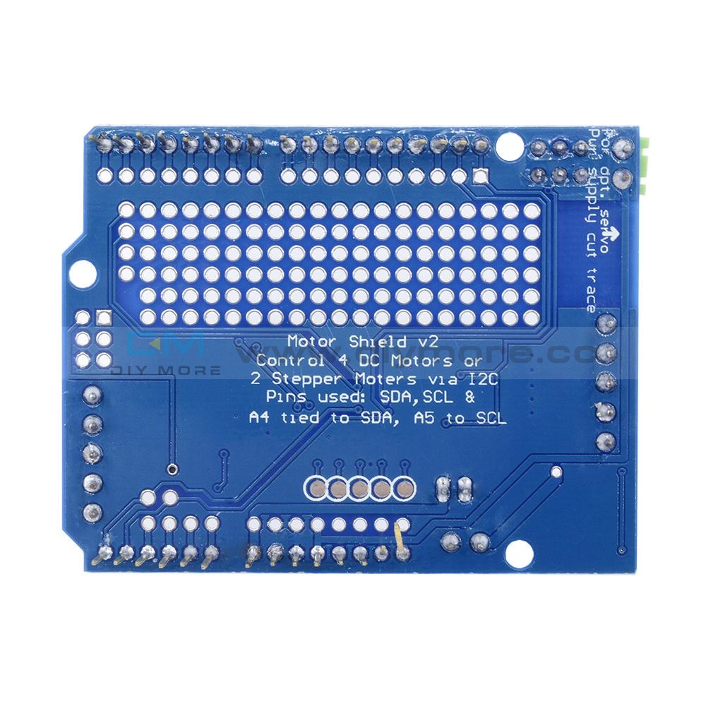
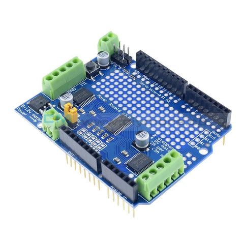 Translation missing: en.products.product.regular_price $18.99{"id":4419937927239,"title":"Dual Mode PWM PULSE Square Wave Rectangular Wave Signal Adjustable Generator Control Module DC Stepper Motor Drive Driver Board","handle":"dual-mode-pwm-pulse-square-wave-rectangular-wave-signal-adjustable-generator-control-module-dc-stepper-motor-drive-driver-board","description":"\u003cdiv\u003e\n\u003cp\u003e\u003cwidget data-widget-type=\"customText\" id=\"33684419\" title=\"Head\" type=\"custom\"\u003e\u003c\/widget\u003e\u003c\/p\u003e\n\u003cp\u003e \u003c\/p\u003e\n\u003cp\u003e\u003cimg src=\"https:\/\/ae01.alicdn.com\/kf\/HTB12JMgilsmBKNjSZFsq6yXSVXaS.jpg\"\u003e\u003c\/p\u003e\n\u003cp\u003e \u003c\/p\u003e\n\u003cp style='box-sizing:content-box;font-size:13px;border-top:0px;font-family:\"Open Sans\", Arial, Helvetica, sans-serif, SimSun, 宋体;border-right:0px;vertical-align:baseline;white-space:normal;word-spacing:0px;border-bottom:0px;text-transform:none;font-weight:400;color:#000000;padding-bottom:0px;font-style:normal;padding-top:0px;padding-left:0px;margin:0px;border-left:0px;orphans:2;widows:2;letter-spacing:normal;padding-right:0px;background-color:#FFFFFF;text-indent:0px;font-variant-ligatures:normal;font-variant-caps:normal;font-variant-numeric:inherit;font-variant-east-asian:inherit;font-stretch:inherit;-webkit-text-stroke-width:0px;text-decoration-style:initial;text-decoration-color:initial;'\u003e\u003cspan style='box-sizing:content-box;font-size:18px;border-top:0px;font-family:\"Trebuchet MS\";border-right:0px;vertical-align:baseline;border-bottom:0px;padding-bottom:0px;padding-top:0px;padding-left:0px;margin:0px;border-left:0px;padding-right:0px;font-stretch:inherit;' data-spm-anchor-id=\"2114.10010108.1000023.i0.70637de6zbrpaz\"\u003e1.PWM signal generator, square wave rectangular wave signal generator\u003c\/span\u003e\u003c\/p\u003e\n\u003cp style='box-sizing:content-box;font-size:13px;border-top:0px;font-family:\"Open Sans\", Arial, Helvetica, sans-serif, SimSun, 宋体;border-right:0px;vertical-align:baseline;white-space:normal;word-spacing:0px;border-bottom:0px;text-transform:none;font-weight:400;color:#000000;padding-bottom:0px;font-style:normal;padding-top:0px;padding-left:0px;margin:0px;border-left:0px;orphans:2;widows:2;letter-spacing:normal;padding-right:0px;background-color:#FFFFFF;text-indent:0px;font-variant-ligatures:normal;font-variant-caps:normal;font-variant-numeric:inherit;font-variant-east-asian:inherit;font-stretch:inherit;-webkit-text-stroke-width:0px;text-decoration-style:initial;text-decoration-color:initial;'\u003e\u003cspan style='box-sizing:content-box;font-size:18px;border-top:0px;font-family:\"Trebuchet MS\";border-right:0px;vertical-align:baseline;border-bottom:0px;padding-bottom:0px;padding-top:0px;padding-left:0px;margin:0px;border-left:0px;padding-right:0px;font-stretch:inherit;'\u003e2. Used to generate square wave rectangular wave signals for controlling DC motor or stepper motor driver; used for servo motor, stepping motor, electric gripper, replacing PLC pulse, etc.\u003c\/span\u003e\u003c\/p\u003e\n\u003cp style='box-sizing:content-box;font-size:13px;border-top:0px;font-family:\"Open Sans\", Arial, Helvetica, sans-serif, SimSun, 宋体;border-right:0px;vertical-align:baseline;white-space:normal;word-spacing:0px;border-bottom:0px;text-transform:none;font-weight:400;color:#000000;padding-bottom:0px;font-style:normal;padding-top:0px;padding-left:0px;margin:0px;border-left:0px;orphans:2;widows:2;letter-spacing:normal;padding-right:0px;background-color:#FFFFFF;text-indent:0px;font-variant-ligatures:normal;font-variant-caps:normal;font-variant-numeric:inherit;font-variant-east-asian:inherit;font-stretch:inherit;-webkit-text-stroke-width:0px;text-decoration-style:initial;text-decoration-color:initial;'\u003e\u003cspan style='box-sizing:content-box;font-size:18px;border-top:0px;font-family:\"Trebuchet MS\";border-right:0px;vertical-align:baseline;border-bottom:0px;padding-bottom:0px;padding-top:0px;padding-left:0px;margin:0px;border-left:0px;padding-right:0px;font-stretch:inherit;'\u003e3. The supporting driver realizes dimming, speed regulation, control of solenoid valve, etc., but can not directly drive the load of the electric motor solenoid valve.\u003c\/span\u003e\u003c\/p\u003e\n\u003cp style='box-sizing:content-box;font-size:13px;border-top:0px;font-family:\"Open Sans\", Arial, Helvetica, sans-serif, SimSun, 宋体;border-right:0px;vertical-align:baseline;white-space:normal;word-spacing:0px;border-bottom:0px;text-transform:none;font-weight:400;color:#000000;padding-bottom:0px;font-style:normal;padding-top:0px;padding-left:0px;margin:0px;border-left:0px;orphans:2;widows:2;letter-spacing:normal;padding-right:0px;background-color:#FFFFFF;text-indent:0px;font-variant-ligatures:normal;font-variant-caps:normal;font-variant-numeric:inherit;font-variant-east-asian:inherit;font-stretch:inherit;-webkit-text-stroke-width:0px;text-decoration-style:initial;text-decoration-color:initial;'\u003e\u003cspan style='box-sizing:content-box;font-size:18px;border-top:0px;font-family:\"Trebuchet MS\";border-right:0px;vertical-align:baseline;border-bottom:0px;padding-bottom:0px;padding-top:0px;padding-left:0px;margin:0px;border-left:0px;padding-right:0px;font-stretch:inherit;'\u003e\u003c\/span\u003e \u003c\/p\u003e\n\u003cp style='box-sizing:content-box;font-size:13px;border-top:0px;font-family:\"Open Sans\", Arial, Helvetica, sans-serif, SimSun, 宋体;border-right:0px;vertical-align:baseline;white-space:normal;word-spacing:0px;border-bottom:0px;text-transform:none;font-weight:400;color:#000000;padding-bottom:0px;font-style:normal;padding-top:0px;padding-left:0px;margin:0px;border-left:0px;orphans:2;widows:2;letter-spacing:normal;padding-right:0px;background-color:#FFFFFF;text-indent:0px;font-variant-ligatures:normal;font-variant-caps:normal;font-variant-numeric:inherit;font-variant-east-asian:inherit;font-stretch:inherit;-webkit-text-stroke-width:0px;text-decoration-style:initial;text-decoration-color:initial;'\u003e\u003cspan style='box-sizing:content-box;font-size:18px;border-top:0px;font-family:\"Trebuchet MS\";border-right:0px;vertical-align:baseline;border-bottom:0px;color:#FF0000;padding-bottom:0px;padding-top:0px;padding-left:0px;margin:0px;border-left:0px;padding-right:0px;font-stretch:inherit;'\u003e1. Product Highlights:\u003c\/span\u003e\u003cbr style=\"box-sizing:content-box;\"\u003e\u003cspan style='box-sizing:content-box;font-size:18px;border-top:0px;font-family:\"Trebuchet MS\";border-right:0px;vertical-align:baseline;border-bottom:0px;padding-bottom:0px;padding-top:0px;padding-left:0px;margin:0px;border-left:0px;padding-right:0px;font-stretch:inherit;'\u003e1.1 Two modes can be selected:\u003c\/span\u003e\u003cbr style=\"box-sizing:content-box;\"\u003e\u003cspan style='box-sizing:content-box;font-size:18px;border-top:0px;font-family:\"Trebuchet MS\";border-right:0px;vertical-align:baseline;border-bottom:0px;padding-bottom:0px;padding-top:0px;padding-left:0px;margin:0px;border-left:0px;padding-right:0px;font-stretch:inherit;'\u003ePWM mode - frequency (continuous), duty cycle, pulse number adjustable;\u003c\/span\u003e\u003cbr style=\"box-sizing:content-box;\"\u003e\u003cspan style='box-sizing:content-box;font-size:18px;border-top:0px;font-family:\"Trebuchet MS\";border-right:0px;vertical-align:baseline;border-bottom:0px;padding-bottom:0px;padding-top:0px;padding-left:0px;margin:0px;border-left:0px;padding-right:0px;font-stretch:inherit;'\u003ePULSE pulse mode - positive pulse width time, negative pulse width time, delay start time, and number of pulses are adjustable.\u003c\/span\u003e\u003cbr style=\"box-sizing:content-box;\"\u003e\u003cspan style='box-sizing:content-box;font-size:18px;border-top:0px;font-family:\"Trebuchet MS\";border-right:0px;vertical-align:baseline;border-bottom:0px;padding-bottom:0px;padding-top:0px;padding-left:0px;margin:0px;border-left:0px;padding-right:0px;font-stretch:inherit;'\u003e1.2 With start and stop button, can control the output and stop of the signal\u003c\/span\u003e\u003cbr style=\"box-sizing:content-box;\"\u003e\u003cspan style='box-sizing:content-box;font-size:18px;border-top:0px;font-family:\"Trebuchet MS\";border-right:0px;vertical-align:baseline;border-bottom:0px;padding-bottom:0px;padding-top:0px;padding-left:0px;margin:0px;border-left:0px;padding-right:0px;font-stretch:inherit;'\u003e1.3 Wide voltage input 3.3-30V, with anti-reverse protection, 5.08mm terminal wiring\u003c\/span\u003e\u003c\/p\u003e\n\u003cp\u003e\u003cbr style='box-sizing:content-box;font-size:13px;font-family:\"Open Sans\", Arial, Helvetica, sans-serif, SimSun, 宋体;white-space:normal;word-spacing:0px;text-transform:none;font-weight:400;color:#000000;font-style:normal;orphans:2;widows:2;letter-spacing:normal;background-color:#FFFFFF;text-indent:0px;font-variant-ligatures:normal;font-variant-caps:normal;-webkit-text-stroke-width:0px;text-decoration-style:initial;text-decoration-color:initial;'\u003e\u003cspan style='box-sizing:content-box;font-size:18px;border-top:0px;font-family:\"Trebuchet MS\";border-right:0px;vertical-align:baseline;white-space:normal;word-spacing:0px;border-bottom:0px;text-transform:none;font-weight:400;color:#FF0000;padding-bottom:0px;font-style:normal;padding-top:0px;padding-left:0px;margin:0px;border-left:0px;orphans:2;widows:2;letter-spacing:normal;padding-right:0px;background-color:#FFFFFF;text-indent:0px;font-variant-ligatures:normal;font-variant-caps:normal;font-variant-numeric:inherit;font-variant-east-asian:inherit;font-stretch:inherit;-webkit-text-stroke-width:0px;text-decoration-style:initial;text-decoration-color:initial;'\u003e2. Technical parameters:\u003c\/span\u003e\u003cbr style='box-sizing:content-box;font-size:13px;font-family:\"Open Sans\", Arial, Helvetica, sans-serif, SimSun, 宋体;white-space:normal;word-spacing:0px;text-transform:none;font-weight:400;color:#000000;font-style:normal;orphans:2;widows:2;letter-spacing:normal;background-color:#FFFFFF;text-indent:0px;font-variant-ligatures:normal;font-variant-caps:normal;-webkit-text-stroke-width:0px;text-decoration-style:initial;text-decoration-color:initial;'\u003e\u003cspan style='box-sizing:content-box;font-size:18px;border-top:0px;font-family:\"Trebuchet MS\";border-right:0px;vertical-align:baseline;white-space:normal;word-spacing:0px;border-bottom:0px;text-transform:none;font-weight:400;color:#000000;padding-bottom:0px;font-style:normal;padding-top:0px;padding-left:0px;margin:0px;border-left:0px;orphans:2;widows:2;letter-spacing:normal;padding-right:0px;background-color:#FFFFFF;text-indent:0px;font-variant-ligatures:normal;font-variant-caps:normal;font-variant-numeric:inherit;font-variant-east-asian:inherit;font-stretch:inherit;-webkit-text-stroke-width:0px;text-decoration-style:initial;text-decoration-color:initial;'\u003e2.1 Working voltage: 3.3~30V, with anti-reverse protection\u003c\/span\u003e\u003cbr style='box-sizing:content-box;font-size:13px;font-family:\"Open Sans\", Arial, Helvetica, sans-serif, SimSun, 宋体;white-space:normal;word-spacing:0px;text-transform:none;font-weight:400;color:#000000;font-style:normal;orphans:2;widows:2;letter-spacing:normal;background-color:#FFFFFF;text-indent:0px;font-variant-ligatures:normal;font-variant-caps:normal;-webkit-text-stroke-width:0px;text-decoration-style:initial;text-decoration-color:initial;'\u003e\u003cspan style='box-sizing:content-box;font-size:18px;border-top:0px;font-family:\"Trebuchet MS\";border-right:0px;vertical-align:baseline;white-space:normal;word-spacing:0px;border-bottom:0px;text-transform:none;font-weight:400;color:#000000;padding-bottom:0px;font-style:normal;padding-top:0px;padding-left:0px;margin:0px;border-left:0px;orphans:2;widows:2;letter-spacing:normal;padding-right:0px;background-color:#FFFFFF;text-indent:0px;font-variant-ligatures:normal;font-variant-caps:normal;font-variant-numeric:inherit;font-variant-east-asian:inherit;font-stretch:inherit;-webkit-text-stroke-width:0px;text-decoration-style:initial;text-decoration-color:initial;'\u003e2.2 Frequency range: 1Hz~150KHz, accuracy about 2%\u003c\/span\u003e\u003cbr style='box-sizing:content-box;font-size:13px;font-family:\"Open Sans\", Arial, Helvetica, sans-serif, SimSun, 宋体;white-space:normal;word-spacing:0px;text-transform:none;font-weight:400;color:#000000;font-style:normal;orphans:2;widows:2;letter-spacing:normal;background-color:#FFFFFF;text-indent:0px;font-variant-ligatures:normal;font-variant-caps:normal;-webkit-text-stroke-width:0px;text-decoration-style:initial;text-decoration-color:initial;'\u003e\u003cspan style='box-sizing:content-box;font-size:18px;border-top:0px;font-family:\"Trebuchet MS\";border-right:0px;vertical-align:baseline;white-space:normal;word-spacing:0px;border-bottom:0px;text-transform:none;font-weight:400;color:#000000;padding-bottom:0px;font-style:normal;padding-top:0px;padding-left:0px;margin:0px;border-left:0px;orphans:2;widows:2;letter-spacing:normal;padding-right:0px;background-color:#FFFFFF;text-indent:0px;font-variant-ligatures:normal;font-variant-caps:normal;font-variant-numeric:inherit;font-variant-east-asian:inherit;font-stretch:inherit;-webkit-text-stroke-width:0px;text-decoration-style:initial;text-decoration-color:initial;'\u003e2.3 duty cycle range: 0-100%, 1% stepping\u003c\/span\u003e\u003cbr style='box-sizing:content-box;font-size:13px;font-family:\"Open Sans\", Arial, Helvetica, sans-serif, SimSun, 宋体;white-space:normal;word-spacing:0px;text-transform:none;font-weight:400;color:#000000;font-style:normal;orphans:2;widows:2;letter-spacing:normal;background-color:#FFFFFF;text-indent:0px;font-variant-ligatures:normal;font-variant-caps:normal;-webkit-text-stroke-width:0px;text-decoration-style:initial;text-decoration-color:initial;'\u003e\u003cspan style='box-sizing:content-box;font-size:18px;border-top:0px;font-family:\"Trebuchet MS\";border-right:0px;vertical-align:baseline;white-space:normal;word-spacing:0px;border-bottom:0px;text-transform:none;font-weight:400;color:#000000;padding-bottom:0px;font-style:normal;padding-top:0px;padding-left:0px;margin:0px;border-left:0px;orphans:2;widows:2;letter-spacing:normal;padding-right:0px;background-color:#FFFFFF;text-indent:0px;font-variant-ligatures:normal;font-variant-caps:normal;font-variant-numeric:inherit;font-variant-east-asian:inherit;font-stretch:inherit;-webkit-text-stroke-width:0px;text-decoration-style:initial;text-decoration-color:initial;'\u003e2.4 number of pulses: 1-9999, or infinite (display ‘----' stands for infinity)\u003c\/span\u003e\u003cbr style='box-sizing:content-box;font-size:13px;font-family:\"Open Sans\", Arial, Helvetica, sans-serif, SimSun, 宋体;white-space:normal;word-spacing:0px;text-transform:none;font-weight:400;color:#000000;font-style:normal;orphans:2;widows:2;letter-spacing:normal;background-color:#FFFFFF;text-indent:0px;font-variant-ligatures:normal;font-variant-caps:normal;-webkit-text-stroke-width:0px;text-decoration-style:initial;text-decoration-color:initial;'\u003e\u003cspan style='box-sizing:content-box;font-size:18px;border-top:0px;font-family:\"Trebuchet MS\";border-right:0px;vertical-align:baseline;white-space:normal;word-spacing:0px;border-bottom:0px;text-transform:none;font-weight:400;color:#000000;padding-bottom:0px;font-style:normal;padding-top:0px;padding-left:0px;margin:0px;border-left:0px;orphans:2;widows:2;letter-spacing:normal;padding-right:0px;background-color:#FFFFFF;text-indent:0px;font-variant-ligatures:normal;font-variant-caps:normal;font-variant-numeric:inherit;font-variant-east-asian:inherit;font-stretch:inherit;-webkit-text-stroke-width:0px;text-decoration-style:initial;text-decoration-color:initial;'\u003e2.5 delay output time: 0.000s-9999s, the minimum can be set 1ms\u003c\/span\u003e\u003cbr style='box-sizing:content-box;font-size:13px;font-family:\"Open Sans\", Arial, Helvetica, sans-serif, SimSun, 宋体;white-space:normal;word-spacing:0px;text-transform:none;font-weight:400;color:#000000;font-style:normal;orphans:2;widows:2;letter-spacing:normal;background-color:#FFFFFF;text-indent:0px;font-variant-ligatures:normal;font-variant-caps:normal;-webkit-text-stroke-width:0px;text-decoration-style:initial;text-decoration-color:initial;'\u003e\u003cspan style='box-sizing:content-box;font-size:18px;border-top:0px;font-family:\"Trebuchet MS\";border-right:0px;vertical-align:baseline;white-space:normal;word-spacing:0px;border-bottom:0px;text-transform:none;font-weight:400;color:#000000;padding-bottom:0px;font-style:normal;padding-top:0px;padding-left:0px;margin:0px;border-left:0px;orphans:2;widows:2;letter-spacing:normal;padding-right:0px;background-color:#FFFFFF;text-indent:0px;font-variant-ligatures:normal;font-variant-caps:normal;font-variant-numeric:inherit;font-variant-east-asian:inherit;font-stretch:inherit;-webkit-text-stroke-width:0px;text-decoration-style:initial;text-decoration-color:initial;'\u003e2.6 positive and negative pulse width length: 0.000s-9999s, the minimum can be set 1ms\u003c\/span\u003e\u003cbr style='box-sizing:content-box;font-size:13px;font-family:\"Open Sans\", Arial, Helvetica, sans-serif, SimSun, 宋体;white-space:normal;word-spacing:0px;text-transform:none;font-weight:400;color:#000000;font-style:normal;orphans:2;widows:2;letter-spacing:normal;background-color:#FFFFFF;text-indent:0px;font-variant-ligatures:normal;font-variant-caps:normal;-webkit-text-stroke-width:0px;text-decoration-style:initial;text-decoration-color:initial;'\u003e\u003cspan style='box-sizing:content-box;font-size:18px;border-top:0px;font-family:\"Trebuchet MS\";border-right:0px;vertical-align:baseline;white-space:normal;word-spacing:0px;border-bottom:0px;text-transform:none;font-weight:400;color:#000000;padding-bottom:0px;font-style:normal;padding-top:0px;padding-left:0px;margin:0px;border-left:0px;orphans:2;widows:2;letter-spacing:normal;padding-right:0px;background-color:#FFFFFF;text-indent:0px;font-variant-ligatures:normal;font-variant-caps:normal;font-variant-numeric:inherit;font-variant-east-asian:inherit;font-stretch:inherit;-webkit-text-stroke-width:0px;text-decoration-style:initial;text-decoration-color:initial;'\u003e2.7 signal loading capacity: less than 30mA\u003c\/span\u003e\u003cbr style='box-sizing:content-box;font-size:13px;font-family:\"Open Sans\", Arial, Helvetica, sans-serif, SimSun, 宋体;white-space:normal;word-spacing:0px;text-transform:none;font-weight:400;color:#000000;font-style:normal;orphans:2;widows:2;letter-spacing:normal;background-color:#FFFFFF;text-indent:0px;font-variant-ligatures:normal;font-variant-caps:normal;-webkit-text-stroke-width:0px;text-decoration-style:initial;text-decoration-color:initial;'\u003e\u003cspan style='box-sizing:content-box;font-size:18px;border-top:0px;font-family:\"Trebuchet MS\";border-right:0px;vertical-align:baseline;white-space:normal;word-spacing:0px;border-bottom:0px;text-transform:none;font-weight:400;color:#000000;padding-bottom:0px;font-style:normal;padding-top:0px;padding-left:0px;margin:0px;border-left:0px;orphans:2;widows:2;letter-spacing:normal;padding-right:0px;background-color:#FFFFFF;text-indent:0px;font-variant-ligatures:normal;font-variant-caps:normal;font-variant-numeric:inherit;font-variant-east-asian:inherit;font-stretch:inherit;-webkit-text-stroke-width:0px;text-decoration-style:initial;text-decoration-color:initial;'\u003e2.8 Output signal amplitude: amplitude is equal to the supply voltage\u003c\/span\u003e\u003cbr style='box-sizing:content-box;font-size:13px;font-family:\"Open Sans\", Arial, Helvetica, sans-serif, SimSun, 宋体;white-space:normal;word-spacing:0px;text-transform:none;font-weight:400;color:#000000;font-style:normal;orphans:2;widows:2;letter-spacing:normal;background-color:#FFFFFF;text-indent:0px;font-variant-ligatures:normal;font-variant-caps:normal;-webkit-text-stroke-width:0px;text-decoration-style:initial;text-decoration-color:initial;'\u003e\u003cspan style='box-sizing:content-box;font-size:18px;border-top:0px;font-family:\"Trebuchet MS\";border-right:0px;vertical-align:baseline;white-space:normal;word-spacing:0px;border-bottom:0px;text-transform:none;font-weight:400;color:#000000;padding-bottom:0px;font-style:normal;padding-top:0px;padding-left:0px;margin:0px;border-left:0px;orphans:2;widows:2;letter-spacing:normal;padding-right:0px;background-color:#FFFFFF;text-indent:0px;font-variant-ligatures:normal;font-variant-caps:normal;font-variant-numeric:inherit;font-variant-east-asian:inherit;font-stretch:inherit;-webkit-text-stroke-width:0px;text-decoration-style:initial;text-decoration-color:initial;'\u003e2.9 Product size: 60mm*32mm*10mm\u003c\/span\u003e\u003cbr style='box-sizing:content-box;font-size:13px;font-family:\"Open Sans\", Arial, Helvetica, sans-serif, SimSun, 宋体;white-space:normal;word-spacing:0px;text-transform:none;font-weight:400;color:#000000;font-style:normal;orphans:2;widows:2;letter-spacing:normal;background-color:#FFFFFF;text-indent:0px;font-variant-ligatures:normal;font-variant-caps:normal;-webkit-text-stroke-width:0px;text-decoration-style:initial;text-decoration-color:initial;'\u003e\u003cspan style='box-sizing:content-box;font-size:18px;border-top:0px;font-family:\"Trebuchet MS\";border-right:0px;vertical-align:baseline;white-space:normal;word-spacing:0px;border-bottom:0px;text-transform:none;font-weight:400;color:#000000;padding-bottom:0px;font-style:normal;padding-top:0px;padding-left:0px;margin:0px;border-left:0px;orphans:2;widows:2;letter-spacing:normal;padding-right:0px;background-color:#FFFFFF;text-indent:0px;font-variant-ligatures:normal;font-variant-caps:normal;font-variant-numeric:inherit;font-variant-east-asian:inherit;font-stretch:inherit;-webkit-text-stroke-width:0px;text-decoration-style:initial;text-decoration-color:initial;'\u003e2.10 Product Weight: 18g\u003c\/span\u003e\u003cbr style='box-sizing:content-box;font-size:13px;font-family:\"Open Sans\", Arial, Helvetica, sans-serif, SimSun, 宋体;white-space:normal;word-spacing:0px;text-transform:none;font-weight:400;color:#000000;font-style:normal;orphans:2;widows:2;letter-spacing:normal;background-color:#FFFFFF;text-indent:0px;font-variant-ligatures:normal;font-variant-caps:normal;-webkit-text-stroke-width:0px;text-decoration-style:initial;text-decoration-color:initial;'\u003e\u003cspan style='box-sizing:content-box;font-size:18px;border-top:0px;font-family:\"Trebuchet MS\";border-right:0px;vertical-align:baseline;white-space:normal;word-spacing:0px;border-bottom:0px;text-transform:none;font-weight:400;color:#000000;padding-bottom:0px;font-style:normal;padding-top:0px;padding-left:0px;margin:0px;border-left:0px;orphans:2;widows:2;letter-spacing:normal;padding-right:0px;background-color:#FFFFFF;text-indent:0px;font-variant-ligatures:normal;font-variant-caps:normal;font-variant-numeric:inherit;font-variant-east-asian:inherit;font-stretch:inherit;-webkit-text-stroke-width:0px;text-decoration-style:initial;text-decoration-color:initial;'\u003e2.11 Packing: Anti-static bag\u003c\/span\u003e\u003cspan style='font-size:13px;font-family:\"Open Sans\", Arial, Helvetica, sans-serif, SimSun, 宋体;white-space:normal;word-spacing:0px;text-transform:none;float:none;font-weight:400;color:#000000;font-style:normal;orphans:2;widows:2;display:inline !important;letter-spacing:normal;background-color:#FFFFFF;text-indent:0px;font-variant-ligatures:normal;font-variant-caps:normal;-webkit-text-stroke-width:0px;text-decoration-style:initial;text-decoration-color:initial;'\u003e\u003c\/span\u003e\u003c\/p\u003e\n\u003cp style='box-sizing:content-box;font-size:13px;border-top:0px;font-family:\"Open Sans\", Arial, Helvetica, sans-serif, SimSun, 宋体;border-right:0px;vertical-align:baseline;white-space:normal;word-spacing:0px;border-bottom:0px;text-transform:none;font-weight:400;color:#000000;padding-bottom:0px;font-style:normal;padding-top:0px;padding-left:0px;margin:0px;border-left:0px;orphans:2;widows:2;letter-spacing:normal;padding-right:0px;background-color:#FFFFFF;text-indent:0px;font-variant-ligatures:normal;font-variant-caps:normal;font-variant-numeric:inherit;font-variant-east-asian:inherit;font-stretch:inherit;-webkit-text-stroke-width:0px;text-decoration-style:initial;text-decoration-color:initial;'\u003e\u003cspan style='box-sizing:content-box;font-size:18px;border-top:0px;font-family:\"Trebuchet MS\";border-right:0px;vertical-align:baseline;border-bottom:0px;padding-bottom:0px;padding-top:0px;padding-left:0px;margin:0px;border-left:0px;padding-right:0px;font-stretch:inherit;'\u003e\u003c\/span\u003e \u003c\/p\u003e\n\u003cp style='box-sizing:content-box;font-size:13px;border-top:0px;font-family:\"Open Sans\", Arial, Helvetica, sans-serif, SimSun, 宋体;border-right:0px;vertical-align:baseline;white-space:normal;word-spacing:0px;border-bottom:0px;text-transform:none;font-weight:400;color:#000000;padding-bottom:0px;font-style:normal;padding-top:0px;padding-left:0px;margin:0px;border-left:0px;orphans:2;widows:2;letter-spacing:normal;padding-right:0px;background-color:#FFFFFF;text-indent:0px;font-variant-ligatures:normal;font-variant-caps:normal;font-variant-numeric:inherit;font-variant-east-asian:inherit;font-stretch:inherit;-webkit-text-stroke-width:0px;text-decoration-style:initial;text-decoration-color:initial;'\u003e\u003cspan style='box-sizing:content-box;font-size:18px;border-top:0px;font-family:\"Trebuchet MS\";border-right:0px;vertical-align:baseline;border-bottom:0px;color:#FF0000;padding-bottom:0px;padding-top:0px;padding-left:0px;margin:0px;border-left:0px;padding-right:0px;font-stretch:inherit;'\u003e3. PWM mode (display has \"%\" for PWM mode)\u003c\/span\u003e\u003c\/p\u003e\n\u003cp style='box-sizing:content-box;font-size:13px;border-top:0px;font-family:\"Open Sans\", Arial, Helvetica, sans-serif, SimSun, 宋体;border-right:0px;vertical-align:baseline;white-space:normal;word-spacing:0px;border-bottom:0px;text-transform:none;font-weight:400;color:#000000;padding-bottom:0px;font-style:normal;padding-top:0px;padding-left:0px;margin:0px;border-left:0px;orphans:2;widows:2;letter-spacing:normal;padding-right:0px;background-color:#FFFFFF;text-indent:0px;font-variant-ligatures:normal;font-variant-caps:normal;font-variant-numeric:inherit;font-variant-east-asian:inherit;font-stretch:inherit;-webkit-text-stroke-width:0px;text-decoration-style:initial;text-decoration-color:initial;'\u003e\u003cspan style='box-sizing:content-box;font-size:18px;border-top:0px;font-family:\"Trebuchet MS\";border-right:0px;vertical-align:baseline;border-bottom:0px;padding-bottom:0px;padding-top:0px;padding-left:0px;margin:0px;border-left:0px;padding-right:0px;font-stretch:inherit;'\u003eThe factory default mode is PWM mode, FREQ+ and FREQ-key set frequency, DUTY+ and DUTY-button set duty cycle; short press STOP button control signal output or stop, stop output is 0, the screen displays “OUT” mark as There is output, otherwise it stops output; the default factory frequency is 1KHZ and the duty cycle is 50%.\u003c\/span\u003e\u003c\/p\u003e\n\u003cp style='box-sizing:content-box;font-size:13px;border-top:0px;font-family:\"Open Sans\", Arial, Helvetica, sans-serif, SimSun, 宋体;border-right:0px;vertical-align:baseline;white-space:normal;word-spacing:0px;border-bottom:0px;text-transform:none;font-weight:400;color:#000000;padding-bottom:0px;font-style:normal;padding-top:0px;padding-left:0px;margin:0px;border-left:0px;orphans:2;widows:2;letter-spacing:normal;padding-right:0px;background-color:#FFFFFF;text-indent:0px;font-variant-ligatures:normal;font-variant-caps:normal;font-variant-numeric:inherit;font-variant-east-asian:inherit;font-stretch:inherit;-webkit-text-stroke-width:0px;text-decoration-style:initial;text-decoration-color:initial;'\u003e\u003cspan style='box-sizing:content-box;font-size:18px;border-top:0px;font-family:\"Trebuchet MS\";border-right:0px;vertical-align:baseline;border-bottom:0px;padding-bottom:0px;padding-top:0px;padding-left:0px;margin:0px;border-left:0px;padding-right:0px;font-stretch:inherit;'\u003eIf you want to switch to PULSE pulse mode, long press the SET button (more than 6 seconds), do not release, you will see the screen change, \"%\" disappears, it is PULSE mode.\u003c\/span\u003e\u003c\/p\u003e\n\u003cp style='box-sizing:content-box;font-size:13px;border-top:0px;font-family:\"Open Sans\", Arial, Helvetica, sans-serif, SimSun, 宋体;border-right:0px;vertical-align:baseline;white-space:normal;word-spacing:0px;border-bottom:0px;text-transform:none;font-weight:400;color:#000000;padding-bottom:0px;font-style:normal;padding-top:0px;padding-left:0px;margin:0px;border-left:0px;orphans:2;widows:2;letter-spacing:normal;padding-right:0px;background-color:#FFFFFF;text-indent:0px;font-variant-ligatures:normal;font-variant-caps:normal;font-variant-numeric:inherit;font-variant-east-asian:inherit;font-stretch:inherit;-webkit-text-stroke-width:0px;text-decoration-style:initial;text-decoration-color:initial;'\u003e\u003cspan style='box-sizing:content-box;font-size:18px;border-top:0px;font-family:\"Trebuchet MS\";border-right:0px;vertical-align:baseline;border-bottom:0px;padding-bottom:0px;padding-top:0px;padding-left:0px;margin:0px;border-left:0px;padding-right:0px;font-stretch:inherit;'\u003e3.2 PULSE pulse mode (No \"%\" on the right side of the display is displayed in PULSE mode)\u003c\/span\u003e\u003c\/p\u003e\n\u003cp style='box-sizing:content-box;font-size:13px;border-top:0px;font-family:\"Open Sans\", Arial, Helvetica, sans-serif, SimSun, 宋体;border-right:0px;vertical-align:baseline;white-space:normal;word-spacing:0px;border-bottom:0px;text-transform:none;font-weight:400;color:#000000;padding-bottom:0px;font-style:normal;padding-top:0px;padding-left:0px;margin:0px;border-left:0px;orphans:2;widows:2;letter-spacing:normal;padding-right:0px;background-color:#FFFFFF;text-indent:0px;font-variant-ligatures:normal;font-variant-caps:normal;font-variant-numeric:inherit;font-variant-east-asian:inherit;font-stretch:inherit;-webkit-text-stroke-width:0px;text-decoration-style:initial;text-decoration-color:initial;'\u003e\u003cspan style='box-sizing:content-box;font-size:18px;border-top:0px;font-family:\"Trebuchet MS\";border-right:0px;vertical-align:baseline;border-bottom:0px;padding-bottom:0px;padding-top:0px;padding-left:0px;margin:0px;border-left:0px;padding-right:0px;font-stretch:inherit;'\u003eThe P+ and P- buttons set the positive pulse width time, the LCD screen shows up, the N+ and N- buttons set the negative pulse width time, the LCD screen displays downwards, the unit is seconds; short press the STOP button to control the signal output or stop, stop output It is 0, the screen displays “OUT” mark as output, otherwise it stops output; the default factory positive pulse width is 0.5 second, and the negative pulse width is 0.5 second.\u003c\/span\u003e\u003c\/p\u003e\n\u003cp style='box-sizing:content-box;font-size:13px;border-top:0px;font-family:\"Open Sans\", Arial, Helvetica, sans-serif, SimSun, 宋体;border-right:0px;vertical-align:baseline;white-space:normal;word-spacing:0px;border-bottom:0px;text-transform:none;font-weight:400;color:#000000;padding-bottom:0px;font-style:normal;padding-top:0px;padding-left:0px;margin:0px;border-left:0px;orphans:2;widows:2;letter-spacing:normal;padding-right:0px;background-color:#FFFFFF;text-indent:0px;font-variant-ligatures:normal;font-variant-caps:normal;font-variant-numeric:inherit;font-variant-east-asian:inherit;font-stretch:inherit;-webkit-text-stroke-width:0px;text-decoration-style:initial;text-decoration-color:initial;'\u003e\u003cspan style='box-sizing:content-box;font-size:18px;border-top:0px;font-family:\"Trebuchet MS\";border-right:0px;vertical-align:baseline;border-bottom:0px;padding-bottom:0px;padding-top:0px;padding-left:0px;margin:0px;border-left:0px;padding-right:0px;font-stretch:inherit;'\u003ePulse number and delay time setting - In PULSE mode, press and hold the SET button for 2 seconds and then release, enter the pulse number and delay time setting interface, the screen displays SET, it will be turned off and cleared after entering. Output pulse; P+ and P- buttons set delay time, N+ and N- buttons set pulse number, factory default delay time is 0 seconds, pulse number is infinite (display ----); Press the button for 2 seconds, automatically return to the pulse interface, press the STOP button, after the delay setting time, start to send the set number of pulses, if the number of pulses is sent, it will automatically output 0, if the period is not sent, press the STOP button. The output pulse will be turned off and cleared, and the number of pulses set will be issued each time it is started.\u003c\/span\u003e\u003c\/p\u003e\n\u003cp style='box-sizing:content-box;font-size:13px;border-top:0px;font-family:\"Open Sans\", Arial, Helvetica, sans-serif, SimSun, 宋体;border-right:0px;vertical-align:baseline;white-space:normal;word-spacing:0px;border-bottom:0px;text-transform:none;font-weight:400;color:#000000;padding-bottom:0px;font-style:normal;padding-top:0px;padding-left:0px;margin:0px;border-left:0px;orphans:2;widows:2;letter-spacing:normal;padding-right:0px;background-color:#FFFFFF;text-indent:0px;font-variant-ligatures:normal;font-variant-caps:normal;font-variant-numeric:inherit;font-variant-east-asian:inherit;font-stretch:inherit;-webkit-text-stroke-width:0px;text-decoration-style:initial;text-decoration-color:initial;'\u003e\u003cspan style='box-sizing:content-box;font-size:18px;border-top:0px;font-family:\"Trebuchet MS\";border-right:0px;vertical-align:baseline;border-bottom:0px;padding-bottom:0px;padding-top:0px;padding-left:0px;margin:0px;border-left:0px;padding-right:0px;font-stretch:inherit;'\u003e3.3 Application Operation Examples\u003c\/span\u003e\u003cbr style=\"box-sizing:content-box;\"\u003e\u003cspan style='box-sizing:content-box;font-size:18px;border-top:0px;font-family:\"Trebuchet MS\";border-right:0px;vertical-align:baseline;border-bottom:0px;padding-bottom:0px;padding-top:0px;padding-left:0px;margin:0px;border-left:0px;padding-right:0px;font-stretch:inherit;'\u003e3.3.1 PWM output 20KHZ, 60% duty cycle: Select PWM mode, the frequency is set to 20.00, and the duty ratio is set to 060%.\u003c\/span\u003e\u003cbr style=\"box-sizing:content-box;\"\u003e\u003cspan style='box-sizing:content-box;font-size:18px;border-top:0px;font-family:\"Trebuchet MS\";border-right:0px;vertical-align:baseline;border-bottom:0px;padding-bottom:0px;padding-top:0px;padding-left:0px;margin:0px;border-left:0px;padding-right:0px;font-stretch:inherit;'\u003e3.3.2 The output is turned on for 0.6 seconds and turned off for 0.2 seconds. Infinite loop: select PULSE mode, the positive pulse width is set to 0.600, the negative pulse width is set to 0.200, the delay time is set to 0.000, and the number of pulses is set to --- -.\u003c\/span\u003e\u003cbr style=\"box-sizing:content-box;\"\u003e\u003cspan style='box-sizing:content-box;font-size:18px;border-top:0px;font-family:\"Trebuchet MS\";border-right:0px;vertical-align:baseline;border-bottom:0px;padding-bottom:0px;padding-top:0px;padding-left:0px;margin:0px;border-left:0px;padding-right:0px;font-stretch:inherit;'\u003e3.3.3 Power on or press the start button, delay 5 seconds, then the output is turned on for 0.6 seconds, off 0.2 seconds, infinite loop: select PULSE mode, positive pulse width is set to 0.600, negative pulse width is set to 0.200, delay The time is set to 5.000 and the number of pulses is set to ----.\u003c\/span\u003e\u003cbr style=\"box-sizing:content-box;\"\u003e\u003cspan style='box-sizing:content-box;font-size:18px;border-top:0px;font-family:\"Trebuchet MS\";border-right:0px;vertical-align:baseline;border-bottom:0px;padding-bottom:0px;padding-top:0px;padding-left:0px;margin:0px;border-left:0px;padding-right:0px;font-stretch:inherit;'\u003e3.3.4 Power on or press the start button, delay 5 seconds, then output high level 10ms low level 10ms pulse 100: select PULSE mode, positive pulse width is set to 0.010, negative pulse width is set to 0.010, delay The time is set to 5.000 and the number of pulses is set to 0100.\u003c\/span\u003e\u003cbr style=\"box-sizing:content-box;\"\u003e\u003cspan style='box-sizing:content-box;font-size:18px;border-top:0px;font-family:\"Trebuchet MS\";border-right:0px;vertical-align:baseline;border-bottom:0px;padding-bottom:0px;padding-top:0px;padding-left:0px;margin:0px;border-left:0px;padding-right:0px;font-stretch:inherit;'\u003e3.3.5 Power-on delay for 10 seconds, then permanently output signal: select PULSE mode, the positive pulse width is set to a number greater than 0, the negative pulse width is set to 0, the delay time is set to 10.00 seconds, and the pulse number is infinite. (----).\u003c\/span\u003e\u003cbr style=\"box-sizing:content-box;\"\u003e\u003cspan style='box-sizing:content-box;font-size:18px;border-top:0px;font-family:\"Trebuchet MS\";border-right:0px;vertical-align:baseline;border-bottom:0px;padding-bottom:0px;padding-top:0px;padding-left:0px;margin:0px;border-left:0px;padding-right:0px;font-stretch:inherit;'\u003e3.3.6 Other applications can explore or consult customer service\u003c\/span\u003e\u003c\/p\u003e\n\u003cp style='box-sizing:content-box;font-size:13px;border-top:0px;font-family:\"Open Sans\", Arial, Helvetica, sans-serif, SimSun, 宋体;border-right:0px;vertical-align:baseline;white-space:normal;word-spacing:0px;border-bottom:0px;text-transform:none;font-weight:400;color:#000000;padding-bottom:0px;font-style:normal;padding-top:0px;padding-left:0px;margin:0px;border-left:0px;orphans:2;widows:2;letter-spacing:normal;padding-right:0px;background-color:#FFFFFF;text-indent:0px;font-variant-ligatures:normal;font-variant-caps:normal;font-variant-numeric:inherit;font-variant-east-asian:inherit;font-stretch:inherit;-webkit-text-stroke-width:0px;text-decoration-style:initial;text-decoration-color:initial;'\u003e\u003cspan style='box-sizing:content-box;font-size:18px;border-top:0px;font-family:\"Trebuchet MS\";border-right:0px;vertical-align:baseline;border-bottom:0px;padding-bottom:0px;padding-top:0px;padding-left:0px;margin:0px;border-left:0px;padding-right:0px;font-stretch:inherit;'\u003eAll setup parameters are not lost when they are turned off.\u003c\/span\u003e\u003c\/p\u003e\n\u003cp style='box-sizing:content-box;font-size:13px;border-top:0px;font-family:\"Open Sans\", Arial, Helvetica, sans-serif, SimSun, 宋体;border-right:0px;vertical-align:baseline;white-space:normal;word-spacing:0px;border-bottom:0px;text-transform:none;font-weight:400;color:#000000;padding-bottom:0px;font-style:normal;padding-top:0px;padding-left:0px;margin:0px;border-left:0px;orphans:2;widows:2;letter-spacing:normal;padding-right:0px;background-color:#FFFFFF;text-indent:0px;font-variant-ligatures:normal;font-variant-caps:normal;font-variant-numeric:inherit;font-variant-east-asian:inherit;font-stretch:inherit;-webkit-text-stroke-width:0px;text-decoration-style:initial;text-decoration-color:initial;'\u003e\u003cspan style='box-sizing:content-box;font-size:18px;border-top:0px;font-family:\"Trebuchet MS\";border-right:0px;vertical-align:baseline;border-bottom:0px;padding-bottom:0px;padding-top:0px;padding-left:0px;margin:0px;border-left:0px;padding-right:0px;font-stretch:inherit;'\u003e\u003c\/span\u003e \u003c\/p\u003e\n\u003cp style='box-sizing:content-box;font-size:13px;border-top:0px;font-family:\"Open Sans\", Arial, Helvetica, sans-serif, SimSun, 宋体;border-right:0px;vertical-align:baseline;white-space:normal;word-spacing:0px;border-bottom:0px;text-transform:none;font-weight:400;color:#000000;padding-bottom:0px;font-style:normal;padding-top:0px;padding-left:0px;margin:0px;border-left:0px;orphans:2;widows:2;letter-spacing:normal;padding-right:0px;background-color:#FFFFFF;text-indent:0px;font-variant-ligatures:normal;font-variant-caps:normal;font-variant-numeric:inherit;font-variant-east-asian:inherit;font-stretch:inherit;-webkit-text-stroke-width:0px;text-decoration-style:initial;text-decoration-color:initial;'\u003e\u003cspan style='box-sizing:content-box;font-size:18px;border-top:0px;font-family:\"Trebuchet MS\";border-right:0px;vertical-align:baseline;border-bottom:0px;padding-bottom:0px;padding-top:0px;padding-left:0px;margin:0px;border-left:0px;padding-right:0px;font-stretch:inherit;'\u003e\u003c\/span\u003e \u003c\/p\u003e\n\u003cspan style='box-sizing:content-box;font-size:18px;border-top:0px;font-family:\"Trebuchet MS\";border-right:0px;vertical-align:baseline;border-bottom:0px;padding-bottom:0px;padding-top:0px;padding-left:0px;margin:0px;border-left:0px;padding-right:0px;font-stretch:inherit;'\u003e \u003cp\u003e\u003cimg src=\"https:\/\/ae01.alicdn.com\/kf\/HTB1VXjubuUXBuNjt_a0q6AysXXaA.jpg\"\u003e\u003c\/p\u003e\n\u003cp\u003e \u003c\/p\u003e\n\u003cp\u003e\u003cimg style=\"width:1000px;\" src=\"https:\/\/ae01.alicdn.com\/kf\/HTB1_riVa2WG3KVjSZFPq6xaiXXak.jpg\"\u003e\u003c\/p\u003e\n\u003cp\u003e\u003cimg style=\"width:1000px;\" src=\"https:\/\/ae01.alicdn.com\/kf\/HTB1MxCVa.GF3KVjSZFoq6zmpFXas.jpg\"\u003e\u003c\/p\u003e\n\u003cp\u003e\u003cimg style=\"width:1000px;\" src=\"https:\/\/ae01.alicdn.com\/kf\/HTB17Z15aWSs3KVjSZPiq6AsiVXaQ.jpg\"\u003e\u003c\/p\u003e\n\u003cp\u003e\u003cimg src=\"https:\/\/ae01.alicdn.com\/kf\/HTB1Hc.uimcqBKNjSZFgq6x_kXXaq.jpg\"\u003e\u003c\/p\u003e\n\u003cp\u003e \u003c\/p\u003e\n\u003cwidget data-widget-type=\"customText\" id=\"24006699\" title=\"Related\" type=\"custom\"\u003e\u003c\/widget\u003e\r \u003cp\u003e\u003c\/p\u003e\u003c\/span\u003e \u003cp\u003e \u003cscript\u003ewindow.adminAccountId=227552571;\u003c\/script\u003e \u003c\/p\u003e\n\u003c\/div\u003e","published_at":"2019-12-27T16:27:56+08:00","created_at":"2019-12-27T16:28:04+08:00","vendor":"diymore","type":"Motor Driver Module","tags":[],"price":599,"price_min":599,"price_max":599,"available":true,"price_varies":false,"compare_at_price":470,"compare_at_price_min":470,"compare_at_price_max":470,"compare_at_price_varies":false,"variants":[{"id":31582605639751,"title":"Default Title","option1":"Default Title","option2":null,"option3":null,"sku":"X13468","requires_shipping":true,"taxable":true,"featured_image":null,"available":true,"name":"Dual Mode PWM PULSE Square Wave Rectangular Wave Signal Adjustable Generator Control Module DC Stepper Motor Drive Driver Board","public_title":null,"options":["Default Title"],"price":599,"weight":0,"compare_at_price":470,"inventory_management":null,"barcode":"","requires_selling_plan":false,"selling_plan_allocations":[],"quantity_rule":{"min":1,"max":null,"increment":1}}],"images":["\/\/www.diymore.cc\/cdn\/shop\/products\/Dual-Mode-PWM-PULSE-Square-Wave-Rectangular-Wave-Signal-Adjustable-Generator-Control-Module-DC-Stepper-Motor_865.jpg?v=1588697869","\/\/www.diymore.cc\/cdn\/shop\/products\/Dual-Mode-PWM-PULSE-Square-Wave-Rectangular-Wave-Signal-Adjustable-Generator-Control-Module-DC-Stepper-Motor_9510e498-27ea-40b5-a8e9-1a342cd00df5_557.jpg?v=1588697869","\/\/www.diymore.cc\/cdn\/shop\/products\/Dual-Mode-PWM-PULSE-Square-Wave-Rectangular-Wave-Signal-Adjustable-Generator-Control-Module-DC-Stepper-Motor_a6256ea5-3d8f-458d-b789-8601fb359396_359.jpg?v=1588697869"],"featured_image":"\/\/www.diymore.cc\/cdn\/shop\/products\/Dual-Mode-PWM-PULSE-Square-Wave-Rectangular-Wave-Signal-Adjustable-Generator-Control-Module-DC-Stepper-Motor_865.jpg?v=1588697869","options":["Title"],"media":[{"alt":"Dual Mode Pwm Pulse Square Wave Rectangular Signal Adjustable Generator Control Module Dc Stepper","id":6682314965063,"position":1,"preview_image":{"aspect_ratio":1.0,"height":1000,"width":1000,"src":"\/\/www.diymore.cc\/cdn\/shop\/products\/Dual-Mode-PWM-PULSE-Square-Wave-Rectangular-Wave-Signal-Adjustable-Generator-Control-Module-DC-Stepper-Motor_865.jpg?v=1588697869"},"aspect_ratio":1.0,"height":1000,"media_type":"image","src":"\/\/www.diymore.cc\/cdn\/shop\/products\/Dual-Mode-PWM-PULSE-Square-Wave-Rectangular-Wave-Signal-Adjustable-Generator-Control-Module-DC-Stepper-Motor_865.jpg?v=1588697869","width":1000},{"alt":"Dual Mode Pwm Pulse Square Wave Rectangular Signal Adjustable Generator Control Module Dc Stepper","id":6682315227207,"position":2,"preview_image":{"aspect_ratio":1.0,"height":1000,"width":1000,"src":"\/\/www.diymore.cc\/cdn\/shop\/products\/Dual-Mode-PWM-PULSE-Square-Wave-Rectangular-Wave-Signal-Adjustable-Generator-Control-Module-DC-Stepper-Motor_9510e498-27ea-40b5-a8e9-1a342cd00df5_557.jpg?v=1588697869"},"aspect_ratio":1.0,"height":1000,"media_type":"image","src":"\/\/www.diymore.cc\/cdn\/shop\/products\/Dual-Mode-PWM-PULSE-Square-Wave-Rectangular-Wave-Signal-Adjustable-Generator-Control-Module-DC-Stepper-Motor_9510e498-27ea-40b5-a8e9-1a342cd00df5_557.jpg?v=1588697869","width":1000},{"alt":"Dual Mode Pwm Pulse Square Wave Rectangular Signal Adjustable Generator Control Module Dc Stepper","id":6682315292743,"position":3,"preview_image":{"aspect_ratio":1.0,"height":1000,"width":1000,"src":"\/\/www.diymore.cc\/cdn\/shop\/products\/Dual-Mode-PWM-PULSE-Square-Wave-Rectangular-Wave-Signal-Adjustable-Generator-Control-Module-DC-Stepper-Motor_a6256ea5-3d8f-458d-b789-8601fb359396_359.jpg?v=1588697869"},"aspect_ratio":1.0,"height":1000,"media_type":"image","src":"\/\/www.diymore.cc\/cdn\/shop\/products\/Dual-Mode-PWM-PULSE-Square-Wave-Rectangular-Wave-Signal-Adjustable-Generator-Control-Module-DC-Stepper-Motor_a6256ea5-3d8f-458d-b789-8601fb359396_359.jpg?v=1588697869","width":1000}],"requires_selling_plan":false,"selling_plan_groups":[],"content":"\u003cdiv\u003e\n\u003cp\u003e\u003cwidget data-widget-type=\"customText\" id=\"33684419\" title=\"Head\" type=\"custom\"\u003e\u003c\/widget\u003e\u003c\/p\u003e\n\u003cp\u003e \u003c\/p\u003e\n\u003cp\u003e\u003cimg src=\"https:\/\/ae01.alicdn.com\/kf\/HTB12JMgilsmBKNjSZFsq6yXSVXaS.jpg\"\u003e\u003c\/p\u003e\n\u003cp\u003e \u003c\/p\u003e\n\u003cp style='box-sizing:content-box;font-size:13px;border-top:0px;font-family:\"Open Sans\", Arial, Helvetica, sans-serif, SimSun, 宋体;border-right:0px;vertical-align:baseline;white-space:normal;word-spacing:0px;border-bottom:0px;text-transform:none;font-weight:400;color:#000000;padding-bottom:0px;font-style:normal;padding-top:0px;padding-left:0px;margin:0px;border-left:0px;orphans:2;widows:2;letter-spacing:normal;padding-right:0px;background-color:#FFFFFF;text-indent:0px;font-variant-ligatures:normal;font-variant-caps:normal;font-variant-numeric:inherit;font-variant-east-asian:inherit;font-stretch:inherit;-webkit-text-stroke-width:0px;text-decoration-style:initial;text-decoration-color:initial;'\u003e\u003cspan style='box-sizing:content-box;font-size:18px;border-top:0px;font-family:\"Trebuchet MS\";border-right:0px;vertical-align:baseline;border-bottom:0px;padding-bottom:0px;padding-top:0px;padding-left:0px;margin:0px;border-left:0px;padding-right:0px;font-stretch:inherit;' data-spm-anchor-id=\"2114.10010108.1000023.i0.70637de6zbrpaz\"\u003e1.PWM signal generator, square wave rectangular wave signal generator\u003c\/span\u003e\u003c\/p\u003e\n\u003cp style='box-sizing:content-box;font-size:13px;border-top:0px;font-family:\"Open Sans\", Arial, Helvetica, sans-serif, SimSun, 宋体;border-right:0px;vertical-align:baseline;white-space:normal;word-spacing:0px;border-bottom:0px;text-transform:none;font-weight:400;color:#000000;padding-bottom:0px;font-style:normal;padding-top:0px;padding-left:0px;margin:0px;border-left:0px;orphans:2;widows:2;letter-spacing:normal;padding-right:0px;background-color:#FFFFFF;text-indent:0px;font-variant-ligatures:normal;font-variant-caps:normal;font-variant-numeric:inherit;font-variant-east-asian:inherit;font-stretch:inherit;-webkit-text-stroke-width:0px;text-decoration-style:initial;text-decoration-color:initial;'\u003e\u003cspan style='box-sizing:content-box;font-size:18px;border-top:0px;font-family:\"Trebuchet MS\";border-right:0px;vertical-align:baseline;border-bottom:0px;padding-bottom:0px;padding-top:0px;padding-left:0px;margin:0px;border-left:0px;padding-right:0px;font-stretch:inherit;'\u003e2. Used to generate square wave rectangular wave signals for controlling DC motor or stepper motor driver; used for servo motor, stepping motor, electric gripper, replacing PLC pulse, etc.\u003c\/span\u003e\u003c\/p\u003e\n\u003cp style='box-sizing:content-box;font-size:13px;border-top:0px;font-family:\"Open Sans\", Arial, Helvetica, sans-serif, SimSun, 宋体;border-right:0px;vertical-align:baseline;white-space:normal;word-spacing:0px;border-bottom:0px;text-transform:none;font-weight:400;color:#000000;padding-bottom:0px;font-style:normal;padding-top:0px;padding-left:0px;margin:0px;border-left:0px;orphans:2;widows:2;letter-spacing:normal;padding-right:0px;background-color:#FFFFFF;text-indent:0px;font-variant-ligatures:normal;font-variant-caps:normal;font-variant-numeric:inherit;font-variant-east-asian:inherit;font-stretch:inherit;-webkit-text-stroke-width:0px;text-decoration-style:initial;text-decoration-color:initial;'\u003e\u003cspan style='box-sizing:content-box;font-size:18px;border-top:0px;font-family:\"Trebuchet MS\";border-right:0px;vertical-align:baseline;border-bottom:0px;padding-bottom:0px;padding-top:0px;padding-left:0px;margin:0px;border-left:0px;padding-right:0px;font-stretch:inherit;'\u003e3. The supporting driver realizes dimming, speed regulation, control of solenoid valve, etc., but can not directly drive the load of the electric motor solenoid valve.\u003c\/span\u003e\u003c\/p\u003e\n\u003cp style='box-sizing:content-box;font-size:13px;border-top:0px;font-family:\"Open Sans\", Arial, Helvetica, sans-serif, SimSun, 宋体;border-right:0px;vertical-align:baseline;white-space:normal;word-spacing:0px;border-bottom:0px;text-transform:none;font-weight:400;color:#000000;padding-bottom:0px;font-style:normal;padding-top:0px;padding-left:0px;margin:0px;border-left:0px;orphans:2;widows:2;letter-spacing:normal;padding-right:0px;background-color:#FFFFFF;text-indent:0px;font-variant-ligatures:normal;font-variant-caps:normal;font-variant-numeric:inherit;font-variant-east-asian:inherit;font-stretch:inherit;-webkit-text-stroke-width:0px;text-decoration-style:initial;text-decoration-color:initial;'\u003e\u003cspan style='box-sizing:content-box;font-size:18px;border-top:0px;font-family:\"Trebuchet MS\";border-right:0px;vertical-align:baseline;border-bottom:0px;padding-bottom:0px;padding-top:0px;padding-left:0px;margin:0px;border-left:0px;padding-right:0px;font-stretch:inherit;'\u003e\u003c\/span\u003e \u003c\/p\u003e\n\u003cp style='box-sizing:content-box;font-size:13px;border-top:0px;font-family:\"Open Sans\", Arial, Helvetica, sans-serif, SimSun, 宋体;border-right:0px;vertical-align:baseline;white-space:normal;word-spacing:0px;border-bottom:0px;text-transform:none;font-weight:400;color:#000000;padding-bottom:0px;font-style:normal;padding-top:0px;padding-left:0px;margin:0px;border-left:0px;orphans:2;widows:2;letter-spacing:normal;padding-right:0px;background-color:#FFFFFF;text-indent:0px;font-variant-ligatures:normal;font-variant-caps:normal;font-variant-numeric:inherit;font-variant-east-asian:inherit;font-stretch:inherit;-webkit-text-stroke-width:0px;text-decoration-style:initial;text-decoration-color:initial;'\u003e\u003cspan style='box-sizing:content-box;font-size:18px;border-top:0px;font-family:\"Trebuchet MS\";border-right:0px;vertical-align:baseline;border-bottom:0px;color:#FF0000;padding-bottom:0px;padding-top:0px;padding-left:0px;margin:0px;border-left:0px;padding-right:0px;font-stretch:inherit;'\u003e1. Product Highlights:\u003c\/span\u003e\u003cbr style=\"box-sizing:content-box;\"\u003e\u003cspan style='box-sizing:content-box;font-size:18px;border-top:0px;font-family:\"Trebuchet MS\";border-right:0px;vertical-align:baseline;border-bottom:0px;padding-bottom:0px;padding-top:0px;padding-left:0px;margin:0px;border-left:0px;padding-right:0px;font-stretch:inherit;'\u003e1.1 Two modes can be selected:\u003c\/span\u003e\u003cbr style=\"box-sizing:content-box;\"\u003e\u003cspan style='box-sizing:content-box;font-size:18px;border-top:0px;font-family:\"Trebuchet MS\";border-right:0px;vertical-align:baseline;border-bottom:0px;padding-bottom:0px;padding-top:0px;padding-left:0px;margin:0px;border-left:0px;padding-right:0px;font-stretch:inherit;'\u003ePWM mode - frequency (continuous), duty cycle, pulse number adjustable;\u003c\/span\u003e\u003cbr style=\"box-sizing:content-box;\"\u003e\u003cspan style='box-sizing:content-box;font-size:18px;border-top:0px;font-family:\"Trebuchet MS\";border-right:0px;vertical-align:baseline;border-bottom:0px;padding-bottom:0px;padding-top:0px;padding-left:0px;margin:0px;border-left:0px;padding-right:0px;font-stretch:inherit;'\u003ePULSE pulse mode - positive pulse width time, negative pulse width time, delay start time, and number of pulses are adjustable.\u003c\/span\u003e\u003cbr style=\"box-sizing:content-box;\"\u003e\u003cspan style='box-sizing:content-box;font-size:18px;border-top:0px;font-family:\"Trebuchet MS\";border-right:0px;vertical-align:baseline;border-bottom:0px;padding-bottom:0px;padding-top:0px;padding-left:0px;margin:0px;border-left:0px;padding-right:0px;font-stretch:inherit;'\u003e1.2 With start and stop button, can control the output and stop of the signal\u003c\/span\u003e\u003cbr style=\"box-sizing:content-box;\"\u003e\u003cspan style='box-sizing:content-box;font-size:18px;border-top:0px;font-family:\"Trebuchet MS\";border-right:0px;vertical-align:baseline;border-bottom:0px;padding-bottom:0px;padding-top:0px;padding-left:0px;margin:0px;border-left:0px;padding-right:0px;font-stretch:inherit;'\u003e1.3 Wide voltage input 3.3-30V, with anti-reverse protection, 5.08mm terminal wiring\u003c\/span\u003e\u003c\/p\u003e\n\u003cp\u003e\u003cbr style='box-sizing:content-box;font-size:13px;font-family:\"Open Sans\", Arial, Helvetica, sans-serif, SimSun, 宋体;white-space:normal;word-spacing:0px;text-transform:none;font-weight:400;color:#000000;font-style:normal;orphans:2;widows:2;letter-spacing:normal;background-color:#FFFFFF;text-indent:0px;font-variant-ligatures:normal;font-variant-caps:normal;-webkit-text-stroke-width:0px;text-decoration-style:initial;text-decoration-color:initial;'\u003e\u003cspan style='box-sizing:content-box;font-size:18px;border-top:0px;font-family:\"Trebuchet MS\";border-right:0px;vertical-align:baseline;white-space:normal;word-spacing:0px;border-bottom:0px;text-transform:none;font-weight:400;color:#FF0000;padding-bottom:0px;font-style:normal;padding-top:0px;padding-left:0px;margin:0px;border-left:0px;orphans:2;widows:2;letter-spacing:normal;padding-right:0px;background-color:#FFFFFF;text-indent:0px;font-variant-ligatures:normal;font-variant-caps:normal;font-variant-numeric:inherit;font-variant-east-asian:inherit;font-stretch:inherit;-webkit-text-stroke-width:0px;text-decoration-style:initial;text-decoration-color:initial;'\u003e2. Technical parameters:\u003c\/span\u003e\u003cbr style='box-sizing:content-box;font-size:13px;font-family:\"Open Sans\", Arial, Helvetica, sans-serif, SimSun, 宋体;white-space:normal;word-spacing:0px;text-transform:none;font-weight:400;color:#000000;font-style:normal;orphans:2;widows:2;letter-spacing:normal;background-color:#FFFFFF;text-indent:0px;font-variant-ligatures:normal;font-variant-caps:normal;-webkit-text-stroke-width:0px;text-decoration-style:initial;text-decoration-color:initial;'\u003e\u003cspan style='box-sizing:content-box;font-size:18px;border-top:0px;font-family:\"Trebuchet MS\";border-right:0px;vertical-align:baseline;white-space:normal;word-spacing:0px;border-bottom:0px;text-transform:none;font-weight:400;color:#000000;padding-bottom:0px;font-style:normal;padding-top:0px;padding-left:0px;margin:0px;border-left:0px;orphans:2;widows:2;letter-spacing:normal;padding-right:0px;background-color:#FFFFFF;text-indent:0px;font-variant-ligatures:normal;font-variant-caps:normal;font-variant-numeric:inherit;font-variant-east-asian:inherit;font-stretch:inherit;-webkit-text-stroke-width:0px;text-decoration-style:initial;text-decoration-color:initial;'\u003e2.1 Working voltage: 3.3~30V, with anti-reverse protection\u003c\/span\u003e\u003cbr style='box-sizing:content-box;font-size:13px;font-family:\"Open Sans\", Arial, Helvetica, sans-serif, SimSun, 宋体;white-space:normal;word-spacing:0px;text-transform:none;font-weight:400;color:#000000;font-style:normal;orphans:2;widows:2;letter-spacing:normal;background-color:#FFFFFF;text-indent:0px;font-variant-ligatures:normal;font-variant-caps:normal;-webkit-text-stroke-width:0px;text-decoration-style:initial;text-decoration-color:initial;'\u003e\u003cspan style='box-sizing:content-box;font-size:18px;border-top:0px;font-family:\"Trebuchet MS\";border-right:0px;vertical-align:baseline;white-space:normal;word-spacing:0px;border-bottom:0px;text-transform:none;font-weight:400;color:#000000;padding-bottom:0px;font-style:normal;padding-top:0px;padding-left:0px;margin:0px;border-left:0px;orphans:2;widows:2;letter-spacing:normal;padding-right:0px;background-color:#FFFFFF;text-indent:0px;font-variant-ligatures:normal;font-variant-caps:normal;font-variant-numeric:inherit;font-variant-east-asian:inherit;font-stretch:inherit;-webkit-text-stroke-width:0px;text-decoration-style:initial;text-decoration-color:initial;'\u003e2.2 Frequency range: 1Hz~150KHz, accuracy about 2%\u003c\/span\u003e\u003cbr style='box-sizing:content-box;font-size:13px;font-family:\"Open Sans\", Arial, Helvetica, sans-serif, SimSun, 宋体;white-space:normal;word-spacing:0px;text-transform:none;font-weight:400;color:#000000;font-style:normal;orphans:2;widows:2;letter-spacing:normal;background-color:#FFFFFF;text-indent:0px;font-variant-ligatures:normal;font-variant-caps:normal;-webkit-text-stroke-width:0px;text-decoration-style:initial;text-decoration-color:initial;'\u003e\u003cspan style='box-sizing:content-box;font-size:18px;border-top:0px;font-family:\"Trebuchet MS\";border-right:0px;vertical-align:baseline;white-space:normal;word-spacing:0px;border-bottom:0px;text-transform:none;font-weight:400;color:#000000;padding-bottom:0px;font-style:normal;padding-top:0px;padding-left:0px;margin:0px;border-left:0px;orphans:2;widows:2;letter-spacing:normal;padding-right:0px;background-color:#FFFFFF;text-indent:0px;font-variant-ligatures:normal;font-variant-caps:normal;font-variant-numeric:inherit;font-variant-east-asian:inherit;font-stretch:inherit;-webkit-text-stroke-width:0px;text-decoration-style:initial;text-decoration-color:initial;'\u003e2.3 duty cycle range: 0-100%, 1% stepping\u003c\/span\u003e\u003cbr style='box-sizing:content-box;font-size:13px;font-family:\"Open Sans\", Arial, Helvetica, sans-serif, SimSun, 宋体;white-space:normal;word-spacing:0px;text-transform:none;font-weight:400;color:#000000;font-style:normal;orphans:2;widows:2;letter-spacing:normal;background-color:#FFFFFF;text-indent:0px;font-variant-ligatures:normal;font-variant-caps:normal;-webkit-text-stroke-width:0px;text-decoration-style:initial;text-decoration-color:initial;'\u003e\u003cspan style='box-sizing:content-box;font-size:18px;border-top:0px;font-family:\"Trebuchet MS\";border-right:0px;vertical-align:baseline;white-space:normal;word-spacing:0px;border-bottom:0px;text-transform:none;font-weight:400;color:#000000;padding-bottom:0px;font-style:normal;padding-top:0px;padding-left:0px;margin:0px;border-left:0px;orphans:2;widows:2;letter-spacing:normal;padding-right:0px;background-color:#FFFFFF;text-indent:0px;font-variant-ligatures:normal;font-variant-caps:normal;font-variant-numeric:inherit;font-variant-east-asian:inherit;font-stretch:inherit;-webkit-text-stroke-width:0px;text-decoration-style:initial;text-decoration-color:initial;'\u003e2.4 number of pulses: 1-9999, or infinite (display ‘----' stands for infinity)\u003c\/span\u003e\u003cbr style='box-sizing:content-box;font-size:13px;font-family:\"Open Sans\", Arial, Helvetica, sans-serif, SimSun, 宋体;white-space:normal;word-spacing:0px;text-transform:none;font-weight:400;color:#000000;font-style:normal;orphans:2;widows:2;letter-spacing:normal;background-color:#FFFFFF;text-indent:0px;font-variant-ligatures:normal;font-variant-caps:normal;-webkit-text-stroke-width:0px;text-decoration-style:initial;text-decoration-color:initial;'\u003e\u003cspan style='box-sizing:content-box;font-size:18px;border-top:0px;font-family:\"Trebuchet MS\";border-right:0px;vertical-align:baseline;white-space:normal;word-spacing:0px;border-bottom:0px;text-transform:none;font-weight:400;color:#000000;padding-bottom:0px;font-style:normal;padding-top:0px;padding-left:0px;margin:0px;border-left:0px;orphans:2;widows:2;letter-spacing:normal;padding-right:0px;background-color:#FFFFFF;text-indent:0px;font-variant-ligatures:normal;font-variant-caps:normal;font-variant-numeric:inherit;font-variant-east-asian:inherit;font-stretch:inherit;-webkit-text-stroke-width:0px;text-decoration-style:initial;text-decoration-color:initial;'\u003e2.5 delay output time: 0.000s-9999s, the minimum can be set 1ms\u003c\/span\u003e\u003cbr style='box-sizing:content-box;font-size:13px;font-family:\"Open Sans\", Arial, Helvetica, sans-serif, SimSun, 宋体;white-space:normal;word-spacing:0px;text-transform:none;font-weight:400;color:#000000;font-style:normal;orphans:2;widows:2;letter-spacing:normal;background-color:#FFFFFF;text-indent:0px;font-variant-ligatures:normal;font-variant-caps:normal;-webkit-text-stroke-width:0px;text-decoration-style:initial;text-decoration-color:initial;'\u003e\u003cspan style='box-sizing:content-box;font-size:18px;border-top:0px;font-family:\"Trebuchet MS\";border-right:0px;vertical-align:baseline;white-space:normal;word-spacing:0px;border-bottom:0px;text-transform:none;font-weight:400;color:#000000;padding-bottom:0px;font-style:normal;padding-top:0px;padding-left:0px;margin:0px;border-left:0px;orphans:2;widows:2;letter-spacing:normal;padding-right:0px;background-color:#FFFFFF;text-indent:0px;font-variant-ligatures:normal;font-variant-caps:normal;font-variant-numeric:inherit;font-variant-east-asian:inherit;font-stretch:inherit;-webkit-text-stroke-width:0px;text-decoration-style:initial;text-decoration-color:initial;'\u003e2.6 positive and negative pulse width length: 0.000s-9999s, the minimum can be set 1ms\u003c\/span\u003e\u003cbr style='box-sizing:content-box;font-size:13px;font-family:\"Open Sans\", Arial, Helvetica, sans-serif, SimSun, 宋体;white-space:normal;word-spacing:0px;text-transform:none;font-weight:400;color:#000000;font-style:normal;orphans:2;widows:2;letter-spacing:normal;background-color:#FFFFFF;text-indent:0px;font-variant-ligatures:normal;font-variant-caps:normal;-webkit-text-stroke-width:0px;text-decoration-style:initial;text-decoration-color:initial;'\u003e\u003cspan style='box-sizing:content-box;font-size:18px;border-top:0px;font-family:\"Trebuchet MS\";border-right:0px;vertical-align:baseline;white-space:normal;word-spacing:0px;border-bottom:0px;text-transform:none;font-weight:400;color:#000000;padding-bottom:0px;font-style:normal;padding-top:0px;padding-left:0px;margin:0px;border-left:0px;orphans:2;widows:2;letter-spacing:normal;padding-right:0px;background-color:#FFFFFF;text-indent:0px;font-variant-ligatures:normal;font-variant-caps:normal;font-variant-numeric:inherit;font-variant-east-asian:inherit;font-stretch:inherit;-webkit-text-stroke-width:0px;text-decoration-style:initial;text-decoration-color:initial;'\u003e2.7 signal loading capacity: less than 30mA\u003c\/span\u003e\u003cbr style='box-sizing:content-box;font-size:13px;font-family:\"Open Sans\", Arial, Helvetica, sans-serif, SimSun, 宋体;white-space:normal;word-spacing:0px;text-transform:none;font-weight:400;color:#000000;font-style:normal;orphans:2;widows:2;letter-spacing:normal;background-color:#FFFFFF;text-indent:0px;font-variant-ligatures:normal;font-variant-caps:normal;-webkit-text-stroke-width:0px;text-decoration-style:initial;text-decoration-color:initial;'\u003e\u003cspan style='box-sizing:content-box;font-size:18px;border-top:0px;font-family:\"Trebuchet MS\";border-right:0px;vertical-align:baseline;white-space:normal;word-spacing:0px;border-bottom:0px;text-transform:none;font-weight:400;color:#000000;padding-bottom:0px;font-style:normal;padding-top:0px;padding-left:0px;margin:0px;border-left:0px;orphans:2;widows:2;letter-spacing:normal;padding-right:0px;background-color:#FFFFFF;text-indent:0px;font-variant-ligatures:normal;font-variant-caps:normal;font-variant-numeric:inherit;font-variant-east-asian:inherit;font-stretch:inherit;-webkit-text-stroke-width:0px;text-decoration-style:initial;text-decoration-color:initial;'\u003e2.8 Output signal amplitude: amplitude is equal to the supply voltage\u003c\/span\u003e\u003cbr style='box-sizing:content-box;font-size:13px;font-family:\"Open Sans\", Arial, Helvetica, sans-serif, SimSun, 宋体;white-space:normal;word-spacing:0px;text-transform:none;font-weight:400;color:#000000;font-style:normal;orphans:2;widows:2;letter-spacing:normal;background-color:#FFFFFF;text-indent:0px;font-variant-ligatures:normal;font-variant-caps:normal;-webkit-text-stroke-width:0px;text-decoration-style:initial;text-decoration-color:initial;'\u003e\u003cspan style='box-sizing:content-box;font-size:18px;border-top:0px;font-family:\"Trebuchet MS\";border-right:0px;vertical-align:baseline;white-space:normal;word-spacing:0px;border-bottom:0px;text-transform:none;font-weight:400;color:#000000;padding-bottom:0px;font-style:normal;padding-top:0px;padding-left:0px;margin:0px;border-left:0px;orphans:2;widows:2;letter-spacing:normal;padding-right:0px;background-color:#FFFFFF;text-indent:0px;font-variant-ligatures:normal;font-variant-caps:normal;font-variant-numeric:inherit;font-variant-east-asian:inherit;font-stretch:inherit;-webkit-text-stroke-width:0px;text-decoration-style:initial;text-decoration-color:initial;'\u003e2.9 Product size: 60mm*32mm*10mm\u003c\/span\u003e\u003cbr style='box-sizing:content-box;font-size:13px;font-family:\"Open Sans\", Arial, Helvetica, sans-serif, SimSun, 宋体;white-space:normal;word-spacing:0px;text-transform:none;font-weight:400;color:#000000;font-style:normal;orphans:2;widows:2;letter-spacing:normal;background-color:#FFFFFF;text-indent:0px;font-variant-ligatures:normal;font-variant-caps:normal;-webkit-text-stroke-width:0px;text-decoration-style:initial;text-decoration-color:initial;'\u003e\u003cspan style='box-sizing:content-box;font-size:18px;border-top:0px;font-family:\"Trebuchet MS\";border-right:0px;vertical-align:baseline;white-space:normal;word-spacing:0px;border-bottom:0px;text-transform:none;font-weight:400;color:#000000;padding-bottom:0px;font-style:normal;padding-top:0px;padding-left:0px;margin:0px;border-left:0px;orphans:2;widows:2;letter-spacing:normal;padding-right:0px;background-color:#FFFFFF;text-indent:0px;font-variant-ligatures:normal;font-variant-caps:normal;font-variant-numeric:inherit;font-variant-east-asian:inherit;font-stretch:inherit;-webkit-text-stroke-width:0px;text-decoration-style:initial;text-decoration-color:initial;'\u003e2.10 Product Weight: 18g\u003c\/span\u003e\u003cbr style='box-sizing:content-box;font-size:13px;font-family:\"Open Sans\", Arial, Helvetica, sans-serif, SimSun, 宋体;white-space:normal;word-spacing:0px;text-transform:none;font-weight:400;color:#000000;font-style:normal;orphans:2;widows:2;letter-spacing:normal;background-color:#FFFFFF;text-indent:0px;font-variant-ligatures:normal;font-variant-caps:normal;-webkit-text-stroke-width:0px;text-decoration-style:initial;text-decoration-color:initial;'\u003e\u003cspan style='box-sizing:content-box;font-size:18px;border-top:0px;font-family:\"Trebuchet MS\";border-right:0px;vertical-align:baseline;white-space:normal;word-spacing:0px;border-bottom:0px;text-transform:none;font-weight:400;color:#000000;padding-bottom:0px;font-style:normal;padding-top:0px;padding-left:0px;margin:0px;border-left:0px;orphans:2;widows:2;letter-spacing:normal;padding-right:0px;background-color:#FFFFFF;text-indent:0px;font-variant-ligatures:normal;font-variant-caps:normal;font-variant-numeric:inherit;font-variant-east-asian:inherit;font-stretch:inherit;-webkit-text-stroke-width:0px;text-decoration-style:initial;text-decoration-color:initial;'\u003e2.11 Packing: Anti-static bag\u003c\/span\u003e\u003cspan style='font-size:13px;font-family:\"Open Sans\", Arial, Helvetica, sans-serif, SimSun, 宋体;white-space:normal;word-spacing:0px;text-transform:none;float:none;font-weight:400;color:#000000;font-style:normal;orphans:2;widows:2;display:inline !important;letter-spacing:normal;background-color:#FFFFFF;text-indent:0px;font-variant-ligatures:normal;font-variant-caps:normal;-webkit-text-stroke-width:0px;text-decoration-style:initial;text-decoration-color:initial;'\u003e\u003c\/span\u003e\u003c\/p\u003e\n\u003cp style='box-sizing:content-box;font-size:13px;border-top:0px;font-family:\"Open Sans\", Arial, Helvetica, sans-serif, SimSun, 宋体;border-right:0px;vertical-align:baseline;white-space:normal;word-spacing:0px;border-bottom:0px;text-transform:none;font-weight:400;color:#000000;padding-bottom:0px;font-style:normal;padding-top:0px;padding-left:0px;margin:0px;border-left:0px;orphans:2;widows:2;letter-spacing:normal;padding-right:0px;background-color:#FFFFFF;text-indent:0px;font-variant-ligatures:normal;font-variant-caps:normal;font-variant-numeric:inherit;font-variant-east-asian:inherit;font-stretch:inherit;-webkit-text-stroke-width:0px;text-decoration-style:initial;text-decoration-color:initial;'\u003e\u003cspan style='box-sizing:content-box;font-size:18px;border-top:0px;font-family:\"Trebuchet MS\";border-right:0px;vertical-align:baseline;border-bottom:0px;padding-bottom:0px;padding-top:0px;padding-left:0px;margin:0px;border-left:0px;padding-right:0px;font-stretch:inherit;'\u003e\u003c\/span\u003e \u003c\/p\u003e\n\u003cp style='box-sizing:content-box;font-size:13px;border-top:0px;font-family:\"Open Sans\", Arial, Helvetica, sans-serif, SimSun, 宋体;border-right:0px;vertical-align:baseline;white-space:normal;word-spacing:0px;border-bottom:0px;text-transform:none;font-weight:400;color:#000000;padding-bottom:0px;font-style:normal;padding-top:0px;padding-left:0px;margin:0px;border-left:0px;orphans:2;widows:2;letter-spacing:normal;padding-right:0px;background-color:#FFFFFF;text-indent:0px;font-variant-ligatures:normal;font-variant-caps:normal;font-variant-numeric:inherit;font-variant-east-asian:inherit;font-stretch:inherit;-webkit-text-stroke-width:0px;text-decoration-style:initial;text-decoration-color:initial;'\u003e\u003cspan style='box-sizing:content-box;font-size:18px;border-top:0px;font-family:\"Trebuchet MS\";border-right:0px;vertical-align:baseline;border-bottom:0px;color:#FF0000;padding-bottom:0px;padding-top:0px;padding-left:0px;margin:0px;border-left:0px;padding-right:0px;font-stretch:inherit;'\u003e3. PWM mode (display has \"%\" for PWM mode)\u003c\/span\u003e\u003c\/p\u003e\n\u003cp style='box-sizing:content-box;font-size:13px;border-top:0px;font-family:\"Open Sans\", Arial, Helvetica, sans-serif, SimSun, 宋体;border-right:0px;vertical-align:baseline;white-space:normal;word-spacing:0px;border-bottom:0px;text-transform:none;font-weight:400;color:#000000;padding-bottom:0px;font-style:normal;padding-top:0px;padding-left:0px;margin:0px;border-left:0px;orphans:2;widows:2;letter-spacing:normal;padding-right:0px;background-color:#FFFFFF;text-indent:0px;font-variant-ligatures:normal;font-variant-caps:normal;font-variant-numeric:inherit;font-variant-east-asian:inherit;font-stretch:inherit;-webkit-text-stroke-width:0px;text-decoration-style:initial;text-decoration-color:initial;'\u003e\u003cspan style='box-sizing:content-box;font-size:18px;border-top:0px;font-family:\"Trebuchet MS\";border-right:0px;vertical-align:baseline;border-bottom:0px;padding-bottom:0px;padding-top:0px;padding-left:0px;margin:0px;border-left:0px;padding-right:0px;font-stretch:inherit;'\u003eThe factory default mode is PWM mode, FREQ+ and FREQ-key set frequency, DUTY+ and DUTY-button set duty cycle; short press STOP button control signal output or stop, stop output is 0, the screen displays “OUT” mark as There is output, otherwise it stops output; the default factory frequency is 1KHZ and the duty cycle is 50%.\u003c\/span\u003e\u003c\/p\u003e\n\u003cp style='box-sizing:content-box;font-size:13px;border-top:0px;font-family:\"Open Sans\", Arial, Helvetica, sans-serif, SimSun, 宋体;border-right:0px;vertical-align:baseline;white-space:normal;word-spacing:0px;border-bottom:0px;text-transform:none;font-weight:400;color:#000000;padding-bottom:0px;font-style:normal;padding-top:0px;padding-left:0px;margin:0px;border-left:0px;orphans:2;widows:2;letter-spacing:normal;padding-right:0px;background-color:#FFFFFF;text-indent:0px;font-variant-ligatures:normal;font-variant-caps:normal;font-variant-numeric:inherit;font-variant-east-asian:inherit;font-stretch:inherit;-webkit-text-stroke-width:0px;text-decoration-style:initial;text-decoration-color:initial;'\u003e\u003cspan style='box-sizing:content-box;font-size:18px;border-top:0px;font-family:\"Trebuchet MS\";border-right:0px;vertical-align:baseline;border-bottom:0px;padding-bottom:0px;padding-top:0px;padding-left:0px;margin:0px;border-left:0px;padding-right:0px;font-stretch:inherit;'\u003eIf you want to switch to PULSE pulse mode, long press the SET button (more than 6 seconds), do not release, you will see the screen change, \"%\" disappears, it is PULSE mode.\u003c\/span\u003e\u003c\/p\u003e\n\u003cp style='box-sizing:content-box;font-size:13px;border-top:0px;font-family:\"Open Sans\", Arial, Helvetica, sans-serif, SimSun, 宋体;border-right:0px;vertical-align:baseline;white-space:normal;word-spacing:0px;border-bottom:0px;text-transform:none;font-weight:400;color:#000000;padding-bottom:0px;font-style:normal;padding-top:0px;padding-left:0px;margin:0px;border-left:0px;orphans:2;widows:2;letter-spacing:normal;padding-right:0px;background-color:#FFFFFF;text-indent:0px;font-variant-ligatures:normal;font-variant-caps:normal;font-variant-numeric:inherit;font-variant-east-asian:inherit;font-stretch:inherit;-webkit-text-stroke-width:0px;text-decoration-style:initial;text-decoration-color:initial;'\u003e\u003cspan style='box-sizing:content-box;font-size:18px;border-top:0px;font-family:\"Trebuchet MS\";border-right:0px;vertical-align:baseline;border-bottom:0px;padding-bottom:0px;padding-top:0px;padding-left:0px;margin:0px;border-left:0px;padding-right:0px;font-stretch:inherit;'\u003e3.2 PULSE pulse mode (No \"%\" on the right side of the display is displayed in PULSE mode)\u003c\/span\u003e\u003c\/p\u003e\n\u003cp style='box-sizing:content-box;font-size:13px;border-top:0px;font-family:\"Open Sans\", Arial, Helvetica, sans-serif, SimSun, 宋体;border-right:0px;vertical-align:baseline;white-space:normal;word-spacing:0px;border-bottom:0px;text-transform:none;font-weight:400;color:#000000;padding-bottom:0px;font-style:normal;padding-top:0px;padding-left:0px;margin:0px;border-left:0px;orphans:2;widows:2;letter-spacing:normal;padding-right:0px;background-color:#FFFFFF;text-indent:0px;font-variant-ligatures:normal;font-variant-caps:normal;font-variant-numeric:inherit;font-variant-east-asian:inherit;font-stretch:inherit;-webkit-text-stroke-width:0px;text-decoration-style:initial;text-decoration-color:initial;'\u003e\u003cspan style='box-sizing:content-box;font-size:18px;border-top:0px;font-family:\"Trebuchet MS\";border-right:0px;vertical-align:baseline;border-bottom:0px;padding-bottom:0px;padding-top:0px;padding-left:0px;margin:0px;border-left:0px;padding-right:0px;font-stretch:inherit;'\u003eThe P+ and P- buttons set the positive pulse width time, the LCD screen shows up, the N+ and N- buttons set the negative pulse width time, the LCD screen displays downwards, the unit is seconds; short press the STOP button to control the signal output or stop, stop output It is 0, the screen displays “OUT” mark as output, otherwise it stops output; the default factory positive pulse width is 0.5 second, and the negative pulse width is 0.5 second.\u003c\/span\u003e\u003c\/p\u003e\n\u003cp style='box-sizing:content-box;font-size:13px;border-top:0px;font-family:\"Open Sans\", Arial, Helvetica, sans-serif, SimSun, 宋体;border-right:0px;vertical-align:baseline;white-space:normal;word-spacing:0px;border-bottom:0px;text-transform:none;font-weight:400;color:#000000;padding-bottom:0px;font-style:normal;padding-top:0px;padding-left:0px;margin:0px;border-left:0px;orphans:2;widows:2;letter-spacing:normal;padding-right:0px;background-color:#FFFFFF;text-indent:0px;font-variant-ligatures:normal;font-variant-caps:normal;font-variant-numeric:inherit;font-variant-east-asian:inherit;font-stretch:inherit;-webkit-text-stroke-width:0px;text-decoration-style:initial;text-decoration-color:initial;'\u003e\u003cspan style='box-sizing:content-box;font-size:18px;border-top:0px;font-family:\"Trebuchet MS\";border-right:0px;vertical-align:baseline;border-bottom:0px;padding-bottom:0px;padding-top:0px;padding-left:0px;margin:0px;border-left:0px;padding-right:0px;font-stretch:inherit;'\u003ePulse number and delay time setting - In PULSE mode, press and hold the SET button for 2 seconds and then release, enter the pulse number and delay time setting interface, the screen displays SET, it will be turned off and cleared after entering. Output pulse; P+ and P- buttons set delay time, N+ and N- buttons set pulse number, factory default delay time is 0 seconds, pulse number is infinite (display ----); Press the button for 2 seconds, automatically return to the pulse interface, press the STOP button, after the delay setting time, start to send the set number of pulses, if the number of pulses is sent, it will automatically output 0, if the period is not sent, press the STOP button. The output pulse will be turned off and cleared, and the number of pulses set will be issued each time it is started.\u003c\/span\u003e\u003c\/p\u003e\n\u003cp style='box-sizing:content-box;font-size:13px;border-top:0px;font-family:\"Open Sans\", Arial, Helvetica, sans-serif, SimSun, 宋体;border-right:0px;vertical-align:baseline;white-space:normal;word-spacing:0px;border-bottom:0px;text-transform:none;font-weight:400;color:#000000;padding-bottom:0px;font-style:normal;padding-top:0px;padding-left:0px;margin:0px;border-left:0px;orphans:2;widows:2;letter-spacing:normal;padding-right:0px;background-color:#FFFFFF;text-indent:0px;font-variant-ligatures:normal;font-variant-caps:normal;font-variant-numeric:inherit;font-variant-east-asian:inherit;font-stretch:inherit;-webkit-text-stroke-width:0px;text-decoration-style:initial;text-decoration-color:initial;'\u003e\u003cspan style='box-sizing:content-box;font-size:18px;border-top:0px;font-family:\"Trebuchet MS\";border-right:0px;vertical-align:baseline;border-bottom:0px;padding-bottom:0px;padding-top:0px;padding-left:0px;margin:0px;border-left:0px;padding-right:0px;font-stretch:inherit;'\u003e3.3 Application Operation Examples\u003c\/span\u003e\u003cbr style=\"box-sizing:content-box;\"\u003e\u003cspan style='box-sizing:content-box;font-size:18px;border-top:0px;font-family:\"Trebuchet MS\";border-right:0px;vertical-align:baseline;border-bottom:0px;padding-bottom:0px;padding-top:0px;padding-left:0px;margin:0px;border-left:0px;padding-right:0px;font-stretch:inherit;'\u003e3.3.1 PWM output 20KHZ, 60% duty cycle: Select PWM mode, the frequency is set to 20.00, and the duty ratio is set to 060%.\u003c\/span\u003e\u003cbr style=\"box-sizing:content-box;\"\u003e\u003cspan style='box-sizing:content-box;font-size:18px;border-top:0px;font-family:\"Trebuchet MS\";border-right:0px;vertical-align:baseline;border-bottom:0px;padding-bottom:0px;padding-top:0px;padding-left:0px;margin:0px;border-left:0px;padding-right:0px;font-stretch:inherit;'\u003e3.3.2 The output is turned on for 0.6 seconds and turned off for 0.2 seconds. Infinite loop: select PULSE mode, the positive pulse width is set to 0.600, the negative pulse width is set to 0.200, the delay time is set to 0.000, and the number of pulses is set to --- -.\u003c\/span\u003e\u003cbr style=\"box-sizing:content-box;\"\u003e\u003cspan style='box-sizing:content-box;font-size:18px;border-top:0px;font-family:\"Trebuchet MS\";border-right:0px;vertical-align:baseline;border-bottom:0px;padding-bottom:0px;padding-top:0px;padding-left:0px;margin:0px;border-left:0px;padding-right:0px;font-stretch:inherit;'\u003e3.3.3 Power on or press the start button, delay 5 seconds, then the output is turned on for 0.6 seconds, off 0.2 seconds, infinite loop: select PULSE mode, positive pulse width is set to 0.600, negative pulse width is set to 0.200, delay The time is set to 5.000 and the number of pulses is set to ----.\u003c\/span\u003e\u003cbr style=\"box-sizing:content-box;\"\u003e\u003cspan style='box-sizing:content-box;font-size:18px;border-top:0px;font-family:\"Trebuchet MS\";border-right:0px;vertical-align:baseline;border-bottom:0px;padding-bottom:0px;padding-top:0px;padding-left:0px;margin:0px;border-left:0px;padding-right:0px;font-stretch:inherit;'\u003e3.3.4 Power on or press the start button, delay 5 seconds, then output high level 10ms low level 10ms pulse 100: select PULSE mode, positive pulse width is set to 0.010, negative pulse width is set to 0.010, delay The time is set to 5.000 and the number of pulses is set to 0100.\u003c\/span\u003e\u003cbr style=\"box-sizing:content-box;\"\u003e\u003cspan style='box-sizing:content-box;font-size:18px;border-top:0px;font-family:\"Trebuchet MS\";border-right:0px;vertical-align:baseline;border-bottom:0px;padding-bottom:0px;padding-top:0px;padding-left:0px;margin:0px;border-left:0px;padding-right:0px;font-stretch:inherit;'\u003e3.3.5 Power-on delay for 10 seconds, then permanently output signal: select PULSE mode, the positive pulse width is set to a number greater than 0, the negative pulse width is set to 0, the delay time is set to 10.00 seconds, and the pulse number is infinite. (----).\u003c\/span\u003e\u003cbr style=\"box-sizing:content-box;\"\u003e\u003cspan style='box-sizing:content-box;font-size:18px;border-top:0px;font-family:\"Trebuchet MS\";border-right:0px;vertical-align:baseline;border-bottom:0px;padding-bottom:0px;padding-top:0px;padding-left:0px;margin:0px;border-left:0px;padding-right:0px;font-stretch:inherit;'\u003e3.3.6 Other applications can explore or consult customer service\u003c\/span\u003e\u003c\/p\u003e\n\u003cp style='box-sizing:content-box;font-size:13px;border-top:0px;font-family:\"Open Sans\", Arial, Helvetica, sans-serif, SimSun, 宋体;border-right:0px;vertical-align:baseline;white-space:normal;word-spacing:0px;border-bottom:0px;text-transform:none;font-weight:400;color:#000000;padding-bottom:0px;font-style:normal;padding-top:0px;padding-left:0px;margin:0px;border-left:0px;orphans:2;widows:2;letter-spacing:normal;padding-right:0px;background-color:#FFFFFF;text-indent:0px;font-variant-ligatures:normal;font-variant-caps:normal;font-variant-numeric:inherit;font-variant-east-asian:inherit;font-stretch:inherit;-webkit-text-stroke-width:0px;text-decoration-style:initial;text-decoration-color:initial;'\u003e\u003cspan style='box-sizing:content-box;font-size:18px;border-top:0px;font-family:\"Trebuchet MS\";border-right:0px;vertical-align:baseline;border-bottom:0px;padding-bottom:0px;padding-top:0px;padding-left:0px;margin:0px;border-left:0px;padding-right:0px;font-stretch:inherit;'\u003eAll setup parameters are not lost when they are turned off.\u003c\/span\u003e\u003c\/p\u003e\n\u003cp style='box-sizing:content-box;font-size:13px;border-top:0px;font-family:\"Open Sans\", Arial, Helvetica, sans-serif, SimSun, 宋体;border-right:0px;vertical-align:baseline;white-space:normal;word-spacing:0px;border-bottom:0px;text-transform:none;font-weight:400;color:#000000;padding-bottom:0px;font-style:normal;padding-top:0px;padding-left:0px;margin:0px;border-left:0px;orphans:2;widows:2;letter-spacing:normal;padding-right:0px;background-color:#FFFFFF;text-indent:0px;font-variant-ligatures:normal;font-variant-caps:normal;font-variant-numeric:inherit;font-variant-east-asian:inherit;font-stretch:inherit;-webkit-text-stroke-width:0px;text-decoration-style:initial;text-decoration-color:initial;'\u003e\u003cspan style='box-sizing:content-box;font-size:18px;border-top:0px;font-family:\"Trebuchet MS\";border-right:0px;vertical-align:baseline;border-bottom:0px;padding-bottom:0px;padding-top:0px;padding-left:0px;margin:0px;border-left:0px;padding-right:0px;font-stretch:inherit;'\u003e\u003c\/span\u003e \u003c\/p\u003e\n\u003cp style='box-sizing:content-box;font-size:13px;border-top:0px;font-family:\"Open Sans\", Arial, Helvetica, sans-serif, SimSun, 宋体;border-right:0px;vertical-align:baseline;white-space:normal;word-spacing:0px;border-bottom:0px;text-transform:none;font-weight:400;color:#000000;padding-bottom:0px;font-style:normal;padding-top:0px;padding-left:0px;margin:0px;border-left:0px;orphans:2;widows:2;letter-spacing:normal;padding-right:0px;background-color:#FFFFFF;text-indent:0px;font-variant-ligatures:normal;font-variant-caps:normal;font-variant-numeric:inherit;font-variant-east-asian:inherit;font-stretch:inherit;-webkit-text-stroke-width:0px;text-decoration-style:initial;text-decoration-color:initial;'\u003e\u003cspan style='box-sizing:content-box;font-size:18px;border-top:0px;font-family:\"Trebuchet MS\";border-right:0px;vertical-align:baseline;border-bottom:0px;padding-bottom:0px;padding-top:0px;padding-left:0px;margin:0px;border-left:0px;padding-right:0px;font-stretch:inherit;'\u003e\u003c\/span\u003e \u003c\/p\u003e\n\u003cspan style='box-sizing:content-box;font-size:18px;border-top:0px;font-family:\"Trebuchet MS\";border-right:0px;vertical-align:baseline;border-bottom:0px;padding-bottom:0px;padding-top:0px;padding-left:0px;margin:0px;border-left:0px;padding-right:0px;font-stretch:inherit;'\u003e \u003cp\u003e\u003cimg src=\"https:\/\/ae01.alicdn.com\/kf\/HTB1VXjubuUXBuNjt_a0q6AysXXaA.jpg\"\u003e\u003c\/p\u003e\n\u003cp\u003e \u003c\/p\u003e\n\u003cp\u003e\u003cimg style=\"width:1000px;\" src=\"https:\/\/ae01.alicdn.com\/kf\/HTB1_riVa2WG3KVjSZFPq6xaiXXak.jpg\"\u003e\u003c\/p\u003e\n\u003cp\u003e\u003cimg style=\"width:1000px;\" src=\"https:\/\/ae01.alicdn.com\/kf\/HTB1MxCVa.GF3KVjSZFoq6zmpFXas.jpg\"\u003e\u003c\/p\u003e\n\u003cp\u003e\u003cimg style=\"width:1000px;\" src=\"https:\/\/ae01.alicdn.com\/kf\/HTB17Z15aWSs3KVjSZPiq6AsiVXaQ.jpg\"\u003e\u003c\/p\u003e\n\u003cp\u003e\u003cimg src=\"https:\/\/ae01.alicdn.com\/kf\/HTB1Hc.uimcqBKNjSZFgq6x_kXXaq.jpg\"\u003e\u003c\/p\u003e\n\u003cp\u003e \u003c\/p\u003e\n\u003cwidget data-widget-type=\"customText\" id=\"24006699\" title=\"Related\" type=\"custom\"\u003e\u003c\/widget\u003e\r \u003cp\u003e\u003c\/p\u003e\u003c\/span\u003e \u003cp\u003e \u003cscript\u003ewindow.adminAccountId=227552571;\u003c\/script\u003e \u003c\/p\u003e\n\u003c\/div\u003e"}
 -
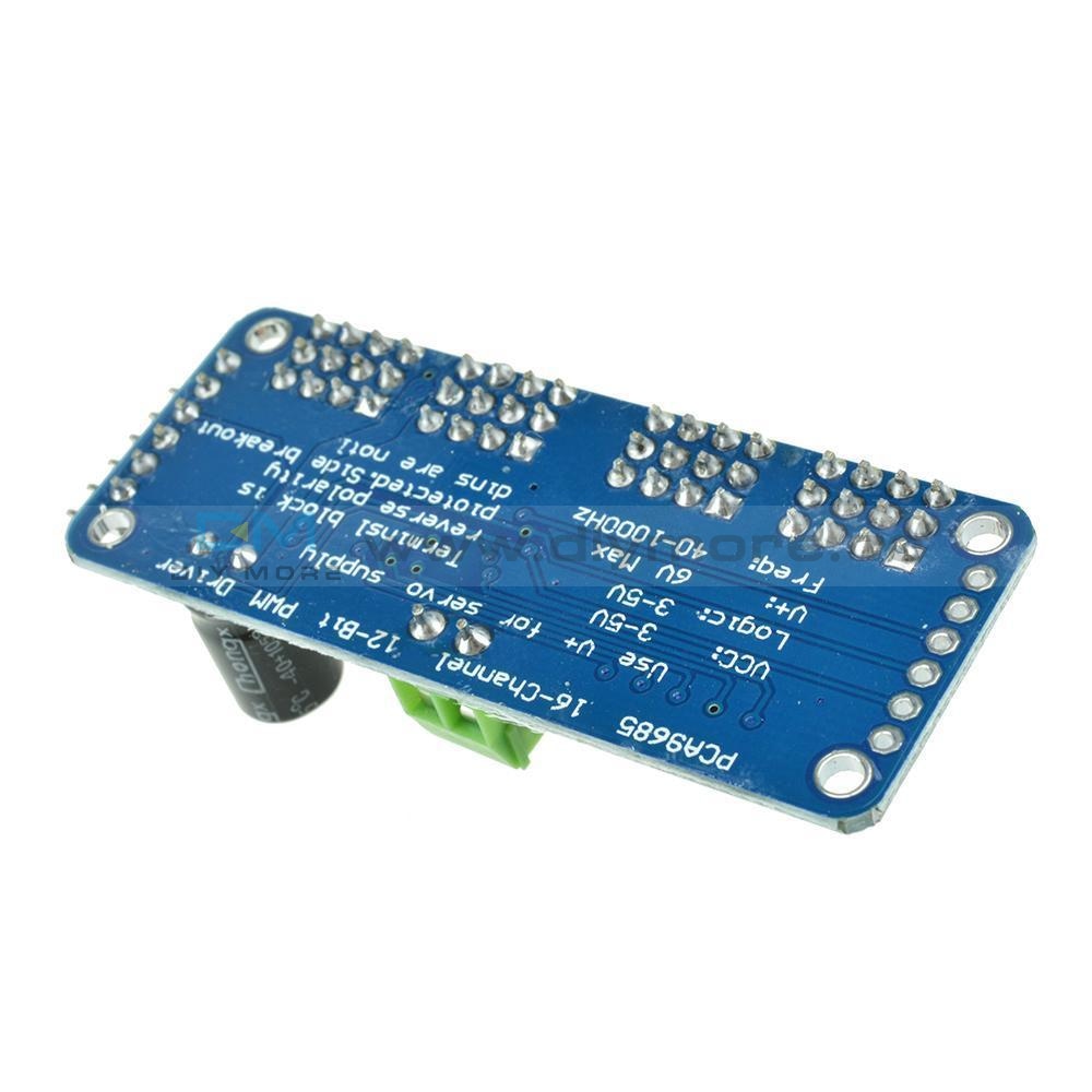
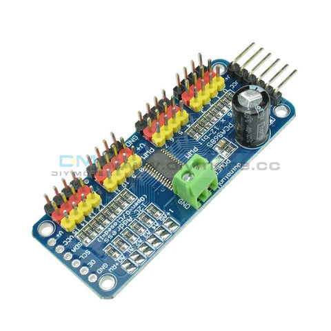 Translation missing: en.products.product.regular_price $5.99{"id":4419937927239,"title":"Dual Mode PWM PULSE Square Wave Rectangular Wave Signal Adjustable Generator Control Module DC Stepper Motor Drive Driver Board","handle":"dual-mode-pwm-pulse-square-wave-rectangular-wave-signal-adjustable-generator-control-module-dc-stepper-motor-drive-driver-board","description":"\u003cdiv\u003e\n\u003cp\u003e\u003cwidget data-widget-type=\"customText\" id=\"33684419\" title=\"Head\" type=\"custom\"\u003e\u003c\/widget\u003e\u003c\/p\u003e\n\u003cp\u003e \u003c\/p\u003e\n\u003cp\u003e\u003cimg src=\"https:\/\/ae01.alicdn.com\/kf\/HTB12JMgilsmBKNjSZFsq6yXSVXaS.jpg\"\u003e\u003c\/p\u003e\n\u003cp\u003e \u003c\/p\u003e\n\u003cp style='box-sizing:content-box;font-size:13px;border-top:0px;font-family:\"Open Sans\", Arial, Helvetica, sans-serif, SimSun, 宋体;border-right:0px;vertical-align:baseline;white-space:normal;word-spacing:0px;border-bottom:0px;text-transform:none;font-weight:400;color:#000000;padding-bottom:0px;font-style:normal;padding-top:0px;padding-left:0px;margin:0px;border-left:0px;orphans:2;widows:2;letter-spacing:normal;padding-right:0px;background-color:#FFFFFF;text-indent:0px;font-variant-ligatures:normal;font-variant-caps:normal;font-variant-numeric:inherit;font-variant-east-asian:inherit;font-stretch:inherit;-webkit-text-stroke-width:0px;text-decoration-style:initial;text-decoration-color:initial;'\u003e\u003cspan style='box-sizing:content-box;font-size:18px;border-top:0px;font-family:\"Trebuchet MS\";border-right:0px;vertical-align:baseline;border-bottom:0px;padding-bottom:0px;padding-top:0px;padding-left:0px;margin:0px;border-left:0px;padding-right:0px;font-stretch:inherit;' data-spm-anchor-id=\"2114.10010108.1000023.i0.70637de6zbrpaz\"\u003e1.PWM signal generator, square wave rectangular wave signal generator\u003c\/span\u003e\u003c\/p\u003e\n\u003cp style='box-sizing:content-box;font-size:13px;border-top:0px;font-family:\"Open Sans\", Arial, Helvetica, sans-serif, SimSun, 宋体;border-right:0px;vertical-align:baseline;white-space:normal;word-spacing:0px;border-bottom:0px;text-transform:none;font-weight:400;color:#000000;padding-bottom:0px;font-style:normal;padding-top:0px;padding-left:0px;margin:0px;border-left:0px;orphans:2;widows:2;letter-spacing:normal;padding-right:0px;background-color:#FFFFFF;text-indent:0px;font-variant-ligatures:normal;font-variant-caps:normal;font-variant-numeric:inherit;font-variant-east-asian:inherit;font-stretch:inherit;-webkit-text-stroke-width:0px;text-decoration-style:initial;text-decoration-color:initial;'\u003e\u003cspan style='box-sizing:content-box;font-size:18px;border-top:0px;font-family:\"Trebuchet MS\";border-right:0px;vertical-align:baseline;border-bottom:0px;padding-bottom:0px;padding-top:0px;padding-left:0px;margin:0px;border-left:0px;padding-right:0px;font-stretch:inherit;'\u003e2. Used to generate square wave rectangular wave signals for controlling DC motor or stepper motor driver; used for servo motor, stepping motor, electric gripper, replacing PLC pulse, etc.\u003c\/span\u003e\u003c\/p\u003e\n\u003cp style='box-sizing:content-box;font-size:13px;border-top:0px;font-family:\"Open Sans\", Arial, Helvetica, sans-serif, SimSun, 宋体;border-right:0px;vertical-align:baseline;white-space:normal;word-spacing:0px;border-bottom:0px;text-transform:none;font-weight:400;color:#000000;padding-bottom:0px;font-style:normal;padding-top:0px;padding-left:0px;margin:0px;border-left:0px;orphans:2;widows:2;letter-spacing:normal;padding-right:0px;background-color:#FFFFFF;text-indent:0px;font-variant-ligatures:normal;font-variant-caps:normal;font-variant-numeric:inherit;font-variant-east-asian:inherit;font-stretch:inherit;-webkit-text-stroke-width:0px;text-decoration-style:initial;text-decoration-color:initial;'\u003e\u003cspan style='box-sizing:content-box;font-size:18px;border-top:0px;font-family:\"Trebuchet MS\";border-right:0px;vertical-align:baseline;border-bottom:0px;padding-bottom:0px;padding-top:0px;padding-left:0px;margin:0px;border-left:0px;padding-right:0px;font-stretch:inherit;'\u003e3. The supporting driver realizes dimming, speed regulation, control of solenoid valve, etc., but can not directly drive the load of the electric motor solenoid valve.\u003c\/span\u003e\u003c\/p\u003e\n\u003cp style='box-sizing:content-box;font-size:13px;border-top:0px;font-family:\"Open Sans\", Arial, Helvetica, sans-serif, SimSun, 宋体;border-right:0px;vertical-align:baseline;white-space:normal;word-spacing:0px;border-bottom:0px;text-transform:none;font-weight:400;color:#000000;padding-bottom:0px;font-style:normal;padding-top:0px;padding-left:0px;margin:0px;border-left:0px;orphans:2;widows:2;letter-spacing:normal;padding-right:0px;background-color:#FFFFFF;text-indent:0px;font-variant-ligatures:normal;font-variant-caps:normal;font-variant-numeric:inherit;font-variant-east-asian:inherit;font-stretch:inherit;-webkit-text-stroke-width:0px;text-decoration-style:initial;text-decoration-color:initial;'\u003e\u003cspan style='box-sizing:content-box;font-size:18px;border-top:0px;font-family:\"Trebuchet MS\";border-right:0px;vertical-align:baseline;border-bottom:0px;padding-bottom:0px;padding-top:0px;padding-left:0px;margin:0px;border-left:0px;padding-right:0px;font-stretch:inherit;'\u003e\u003c\/span\u003e \u003c\/p\u003e\n\u003cp style='box-sizing:content-box;font-size:13px;border-top:0px;font-family:\"Open Sans\", Arial, Helvetica, sans-serif, SimSun, 宋体;border-right:0px;vertical-align:baseline;white-space:normal;word-spacing:0px;border-bottom:0px;text-transform:none;font-weight:400;color:#000000;padding-bottom:0px;font-style:normal;padding-top:0px;padding-left:0px;margin:0px;border-left:0px;orphans:2;widows:2;letter-spacing:normal;padding-right:0px;background-color:#FFFFFF;text-indent:0px;font-variant-ligatures:normal;font-variant-caps:normal;font-variant-numeric:inherit;font-variant-east-asian:inherit;font-stretch:inherit;-webkit-text-stroke-width:0px;text-decoration-style:initial;text-decoration-color:initial;'\u003e\u003cspan style='box-sizing:content-box;font-size:18px;border-top:0px;font-family:\"Trebuchet MS\";border-right:0px;vertical-align:baseline;border-bottom:0px;color:#FF0000;padding-bottom:0px;padding-top:0px;padding-left:0px;margin:0px;border-left:0px;padding-right:0px;font-stretch:inherit;'\u003e1. Product Highlights:\u003c\/span\u003e\u003cbr style=\"box-sizing:content-box;\"\u003e\u003cspan style='box-sizing:content-box;font-size:18px;border-top:0px;font-family:\"Trebuchet MS\";border-right:0px;vertical-align:baseline;border-bottom:0px;padding-bottom:0px;padding-top:0px;padding-left:0px;margin:0px;border-left:0px;padding-right:0px;font-stretch:inherit;'\u003e1.1 Two modes can be selected:\u003c\/span\u003e\u003cbr style=\"box-sizing:content-box;\"\u003e\u003cspan style='box-sizing:content-box;font-size:18px;border-top:0px;font-family:\"Trebuchet MS\";border-right:0px;vertical-align:baseline;border-bottom:0px;padding-bottom:0px;padding-top:0px;padding-left:0px;margin:0px;border-left:0px;padding-right:0px;font-stretch:inherit;'\u003ePWM mode - frequency (continuous), duty cycle, pulse number adjustable;\u003c\/span\u003e\u003cbr style=\"box-sizing:content-box;\"\u003e\u003cspan style='box-sizing:content-box;font-size:18px;border-top:0px;font-family:\"Trebuchet MS\";border-right:0px;vertical-align:baseline;border-bottom:0px;padding-bottom:0px;padding-top:0px;padding-left:0px;margin:0px;border-left:0px;padding-right:0px;font-stretch:inherit;'\u003ePULSE pulse mode - positive pulse width time, negative pulse width time, delay start time, and number of pulses are adjustable.\u003c\/span\u003e\u003cbr style=\"box-sizing:content-box;\"\u003e\u003cspan style='box-sizing:content-box;font-size:18px;border-top:0px;font-family:\"Trebuchet MS\";border-right:0px;vertical-align:baseline;border-bottom:0px;padding-bottom:0px;padding-top:0px;padding-left:0px;margin:0px;border-left:0px;padding-right:0px;font-stretch:inherit;'\u003e1.2 With start and stop button, can control the output and stop of the signal\u003c\/span\u003e\u003cbr style=\"box-sizing:content-box;\"\u003e\u003cspan style='box-sizing:content-box;font-size:18px;border-top:0px;font-family:\"Trebuchet MS\";border-right:0px;vertical-align:baseline;border-bottom:0px;padding-bottom:0px;padding-top:0px;padding-left:0px;margin:0px;border-left:0px;padding-right:0px;font-stretch:inherit;'\u003e1.3 Wide voltage input 3.3-30V, with anti-reverse protection, 5.08mm terminal wiring\u003c\/span\u003e\u003c\/p\u003e\n\u003cp\u003e\u003cbr style='box-sizing:content-box;font-size:13px;font-family:\"Open Sans\", Arial, Helvetica, sans-serif, SimSun, 宋体;white-space:normal;word-spacing:0px;text-transform:none;font-weight:400;color:#000000;font-style:normal;orphans:2;widows:2;letter-spacing:normal;background-color:#FFFFFF;text-indent:0px;font-variant-ligatures:normal;font-variant-caps:normal;-webkit-text-stroke-width:0px;text-decoration-style:initial;text-decoration-color:initial;'\u003e\u003cspan style='box-sizing:content-box;font-size:18px;border-top:0px;font-family:\"Trebuchet MS\";border-right:0px;vertical-align:baseline;white-space:normal;word-spacing:0px;border-bottom:0px;text-transform:none;font-weight:400;color:#FF0000;padding-bottom:0px;font-style:normal;padding-top:0px;padding-left:0px;margin:0px;border-left:0px;orphans:2;widows:2;letter-spacing:normal;padding-right:0px;background-color:#FFFFFF;text-indent:0px;font-variant-ligatures:normal;font-variant-caps:normal;font-variant-numeric:inherit;font-variant-east-asian:inherit;font-stretch:inherit;-webkit-text-stroke-width:0px;text-decoration-style:initial;text-decoration-color:initial;'\u003e2. Technical parameters:\u003c\/span\u003e\u003cbr style='box-sizing:content-box;font-size:13px;font-family:\"Open Sans\", Arial, Helvetica, sans-serif, SimSun, 宋体;white-space:normal;word-spacing:0px;text-transform:none;font-weight:400;color:#000000;font-style:normal;orphans:2;widows:2;letter-spacing:normal;background-color:#FFFFFF;text-indent:0px;font-variant-ligatures:normal;font-variant-caps:normal;-webkit-text-stroke-width:0px;text-decoration-style:initial;text-decoration-color:initial;'\u003e\u003cspan style='box-sizing:content-box;font-size:18px;border-top:0px;font-family:\"Trebuchet MS\";border-right:0px;vertical-align:baseline;white-space:normal;word-spacing:0px;border-bottom:0px;text-transform:none;font-weight:400;color:#000000;padding-bottom:0px;font-style:normal;padding-top:0px;padding-left:0px;margin:0px;border-left:0px;orphans:2;widows:2;letter-spacing:normal;padding-right:0px;background-color:#FFFFFF;text-indent:0px;font-variant-ligatures:normal;font-variant-caps:normal;font-variant-numeric:inherit;font-variant-east-asian:inherit;font-stretch:inherit;-webkit-text-stroke-width:0px;text-decoration-style:initial;text-decoration-color:initial;'\u003e2.1 Working voltage: 3.3~30V, with anti-reverse protection\u003c\/span\u003e\u003cbr style='box-sizing:content-box;font-size:13px;font-family:\"Open Sans\", Arial, Helvetica, sans-serif, SimSun, 宋体;white-space:normal;word-spacing:0px;text-transform:none;font-weight:400;color:#000000;font-style:normal;orphans:2;widows:2;letter-spacing:normal;background-color:#FFFFFF;text-indent:0px;font-variant-ligatures:normal;font-variant-caps:normal;-webkit-text-stroke-width:0px;text-decoration-style:initial;text-decoration-color:initial;'\u003e\u003cspan style='box-sizing:content-box;font-size:18px;border-top:0px;font-family:\"Trebuchet MS\";border-right:0px;vertical-align:baseline;white-space:normal;word-spacing:0px;border-bottom:0px;text-transform:none;font-weight:400;color:#000000;padding-bottom:0px;font-style:normal;padding-top:0px;padding-left:0px;margin:0px;border-left:0px;orphans:2;widows:2;letter-spacing:normal;padding-right:0px;background-color:#FFFFFF;text-indent:0px;font-variant-ligatures:normal;font-variant-caps:normal;font-variant-numeric:inherit;font-variant-east-asian:inherit;font-stretch:inherit;-webkit-text-stroke-width:0px;text-decoration-style:initial;text-decoration-color:initial;'\u003e2.2 Frequency range: 1Hz~150KHz, accuracy about 2%\u003c\/span\u003e\u003cbr style='box-sizing:content-box;font-size:13px;font-family:\"Open Sans\", Arial, Helvetica, sans-serif, SimSun, 宋体;white-space:normal;word-spacing:0px;text-transform:none;font-weight:400;color:#000000;font-style:normal;orphans:2;widows:2;letter-spacing:normal;background-color:#FFFFFF;text-indent:0px;font-variant-ligatures:normal;font-variant-caps:normal;-webkit-text-stroke-width:0px;text-decoration-style:initial;text-decoration-color:initial;'\u003e\u003cspan style='box-sizing:content-box;font-size:18px;border-top:0px;font-family:\"Trebuchet MS\";border-right:0px;vertical-align:baseline;white-space:normal;word-spacing:0px;border-bottom:0px;text-transform:none;font-weight:400;color:#000000;padding-bottom:0px;font-style:normal;padding-top:0px;padding-left:0px;margin:0px;border-left:0px;orphans:2;widows:2;letter-spacing:normal;padding-right:0px;background-color:#FFFFFF;text-indent:0px;font-variant-ligatures:normal;font-variant-caps:normal;font-variant-numeric:inherit;font-variant-east-asian:inherit;font-stretch:inherit;-webkit-text-stroke-width:0px;text-decoration-style:initial;text-decoration-color:initial;'\u003e2.3 duty cycle range: 0-100%, 1% stepping\u003c\/span\u003e\u003cbr style='box-sizing:content-box;font-size:13px;font-family:\"Open Sans\", Arial, Helvetica, sans-serif, SimSun, 宋体;white-space:normal;word-spacing:0px;text-transform:none;font-weight:400;color:#000000;font-style:normal;orphans:2;widows:2;letter-spacing:normal;background-color:#FFFFFF;text-indent:0px;font-variant-ligatures:normal;font-variant-caps:normal;-webkit-text-stroke-width:0px;text-decoration-style:initial;text-decoration-color:initial;'\u003e\u003cspan style='box-sizing:content-box;font-size:18px;border-top:0px;font-family:\"Trebuchet MS\";border-right:0px;vertical-align:baseline;white-space:normal;word-spacing:0px;border-bottom:0px;text-transform:none;font-weight:400;color:#000000;padding-bottom:0px;font-style:normal;padding-top:0px;padding-left:0px;margin:0px;border-left:0px;orphans:2;widows:2;letter-spacing:normal;padding-right:0px;background-color:#FFFFFF;text-indent:0px;font-variant-ligatures:normal;font-variant-caps:normal;font-variant-numeric:inherit;font-variant-east-asian:inherit;font-stretch:inherit;-webkit-text-stroke-width:0px;text-decoration-style:initial;text-decoration-color:initial;'\u003e2.4 number of pulses: 1-9999, or infinite (display ‘----' stands for infinity)\u003c\/span\u003e\u003cbr style='box-sizing:content-box;font-size:13px;font-family:\"Open Sans\", Arial, Helvetica, sans-serif, SimSun, 宋体;white-space:normal;word-spacing:0px;text-transform:none;font-weight:400;color:#000000;font-style:normal;orphans:2;widows:2;letter-spacing:normal;background-color:#FFFFFF;text-indent:0px;font-variant-ligatures:normal;font-variant-caps:normal;-webkit-text-stroke-width:0px;text-decoration-style:initial;text-decoration-color:initial;'\u003e\u003cspan style='box-sizing:content-box;font-size:18px;border-top:0px;font-family:\"Trebuchet MS\";border-right:0px;vertical-align:baseline;white-space:normal;word-spacing:0px;border-bottom:0px;text-transform:none;font-weight:400;color:#000000;padding-bottom:0px;font-style:normal;padding-top:0px;padding-left:0px;margin:0px;border-left:0px;orphans:2;widows:2;letter-spacing:normal;padding-right:0px;background-color:#FFFFFF;text-indent:0px;font-variant-ligatures:normal;font-variant-caps:normal;font-variant-numeric:inherit;font-variant-east-asian:inherit;font-stretch:inherit;-webkit-text-stroke-width:0px;text-decoration-style:initial;text-decoration-color:initial;'\u003e2.5 delay output time: 0.000s-9999s, the minimum can be set 1ms\u003c\/span\u003e\u003cbr style='box-sizing:content-box;font-size:13px;font-family:\"Open Sans\", Arial, Helvetica, sans-serif, SimSun, 宋体;white-space:normal;word-spacing:0px;text-transform:none;font-weight:400;color:#000000;font-style:normal;orphans:2;widows:2;letter-spacing:normal;background-color:#FFFFFF;text-indent:0px;font-variant-ligatures:normal;font-variant-caps:normal;-webkit-text-stroke-width:0px;text-decoration-style:initial;text-decoration-color:initial;'\u003e\u003cspan style='box-sizing:content-box;font-size:18px;border-top:0px;font-family:\"Trebuchet MS\";border-right:0px;vertical-align:baseline;white-space:normal;word-spacing:0px;border-bottom:0px;text-transform:none;font-weight:400;color:#000000;padding-bottom:0px;font-style:normal;padding-top:0px;padding-left:0px;margin:0px;border-left:0px;orphans:2;widows:2;letter-spacing:normal;padding-right:0px;background-color:#FFFFFF;text-indent:0px;font-variant-ligatures:normal;font-variant-caps:normal;font-variant-numeric:inherit;font-variant-east-asian:inherit;font-stretch:inherit;-webkit-text-stroke-width:0px;text-decoration-style:initial;text-decoration-color:initial;'\u003e2.6 positive and negative pulse width length: 0.000s-9999s, the minimum can be set 1ms\u003c\/span\u003e\u003cbr style='box-sizing:content-box;font-size:13px;font-family:\"Open Sans\", Arial, Helvetica, sans-serif, SimSun, 宋体;white-space:normal;word-spacing:0px;text-transform:none;font-weight:400;color:#000000;font-style:normal;orphans:2;widows:2;letter-spacing:normal;background-color:#FFFFFF;text-indent:0px;font-variant-ligatures:normal;font-variant-caps:normal;-webkit-text-stroke-width:0px;text-decoration-style:initial;text-decoration-color:initial;'\u003e\u003cspan style='box-sizing:content-box;font-size:18px;border-top:0px;font-family:\"Trebuchet MS\";border-right:0px;vertical-align:baseline;white-space:normal;word-spacing:0px;border-bottom:0px;text-transform:none;font-weight:400;color:#000000;padding-bottom:0px;font-style:normal;padding-top:0px;padding-left:0px;margin:0px;border-left:0px;orphans:2;widows:2;letter-spacing:normal;padding-right:0px;background-color:#FFFFFF;text-indent:0px;font-variant-ligatures:normal;font-variant-caps:normal;font-variant-numeric:inherit;font-variant-east-asian:inherit;font-stretch:inherit;-webkit-text-stroke-width:0px;text-decoration-style:initial;text-decoration-color:initial;'\u003e2.7 signal loading capacity: less than 30mA\u003c\/span\u003e\u003cbr style='box-sizing:content-box;font-size:13px;font-family:\"Open Sans\", Arial, Helvetica, sans-serif, SimSun, 宋体;white-space:normal;word-spacing:0px;text-transform:none;font-weight:400;color:#000000;font-style:normal;orphans:2;widows:2;letter-spacing:normal;background-color:#FFFFFF;text-indent:0px;font-variant-ligatures:normal;font-variant-caps:normal;-webkit-text-stroke-width:0px;text-decoration-style:initial;text-decoration-color:initial;'\u003e\u003cspan style='box-sizing:content-box;font-size:18px;border-top:0px;font-family:\"Trebuchet MS\";border-right:0px;vertical-align:baseline;white-space:normal;word-spacing:0px;border-bottom:0px;text-transform:none;font-weight:400;color:#000000;padding-bottom:0px;font-style:normal;padding-top:0px;padding-left:0px;margin:0px;border-left:0px;orphans:2;widows:2;letter-spacing:normal;padding-right:0px;background-color:#FFFFFF;text-indent:0px;font-variant-ligatures:normal;font-variant-caps:normal;font-variant-numeric:inherit;font-variant-east-asian:inherit;font-stretch:inherit;-webkit-text-stroke-width:0px;text-decoration-style:initial;text-decoration-color:initial;'\u003e2.8 Output signal amplitude: amplitude is equal to the supply voltage\u003c\/span\u003e\u003cbr style='box-sizing:content-box;font-size:13px;font-family:\"Open Sans\", Arial, Helvetica, sans-serif, SimSun, 宋体;white-space:normal;word-spacing:0px;text-transform:none;font-weight:400;color:#000000;font-style:normal;orphans:2;widows:2;letter-spacing:normal;background-color:#FFFFFF;text-indent:0px;font-variant-ligatures:normal;font-variant-caps:normal;-webkit-text-stroke-width:0px;text-decoration-style:initial;text-decoration-color:initial;'\u003e\u003cspan style='box-sizing:content-box;font-size:18px;border-top:0px;font-family:\"Trebuchet MS\";border-right:0px;vertical-align:baseline;white-space:normal;word-spacing:0px;border-bottom:0px;text-transform:none;font-weight:400;color:#000000;padding-bottom:0px;font-style:normal;padding-top:0px;padding-left:0px;margin:0px;border-left:0px;orphans:2;widows:2;letter-spacing:normal;padding-right:0px;background-color:#FFFFFF;text-indent:0px;font-variant-ligatures:normal;font-variant-caps:normal;font-variant-numeric:inherit;font-variant-east-asian:inherit;font-stretch:inherit;-webkit-text-stroke-width:0px;text-decoration-style:initial;text-decoration-color:initial;'\u003e2.9 Product size: 60mm*32mm*10mm\u003c\/span\u003e\u003cbr style='box-sizing:content-box;font-size:13px;font-family:\"Open Sans\", Arial, Helvetica, sans-serif, SimSun, 宋体;white-space:normal;word-spacing:0px;text-transform:none;font-weight:400;color:#000000;font-style:normal;orphans:2;widows:2;letter-spacing:normal;background-color:#FFFFFF;text-indent:0px;font-variant-ligatures:normal;font-variant-caps:normal;-webkit-text-stroke-width:0px;text-decoration-style:initial;text-decoration-color:initial;'\u003e\u003cspan style='box-sizing:content-box;font-size:18px;border-top:0px;font-family:\"Trebuchet MS\";border-right:0px;vertical-align:baseline;white-space:normal;word-spacing:0px;border-bottom:0px;text-transform:none;font-weight:400;color:#000000;padding-bottom:0px;font-style:normal;padding-top:0px;padding-left:0px;margin:0px;border-left:0px;orphans:2;widows:2;letter-spacing:normal;padding-right:0px;background-color:#FFFFFF;text-indent:0px;font-variant-ligatures:normal;font-variant-caps:normal;font-variant-numeric:inherit;font-variant-east-asian:inherit;font-stretch:inherit;-webkit-text-stroke-width:0px;text-decoration-style:initial;text-decoration-color:initial;'\u003e2.10 Product Weight: 18g\u003c\/span\u003e\u003cbr style='box-sizing:content-box;font-size:13px;font-family:\"Open Sans\", Arial, Helvetica, sans-serif, SimSun, 宋体;white-space:normal;word-spacing:0px;text-transform:none;font-weight:400;color:#000000;font-style:normal;orphans:2;widows:2;letter-spacing:normal;background-color:#FFFFFF;text-indent:0px;font-variant-ligatures:normal;font-variant-caps:normal;-webkit-text-stroke-width:0px;text-decoration-style:initial;text-decoration-color:initial;'\u003e\u003cspan style='box-sizing:content-box;font-size:18px;border-top:0px;font-family:\"Trebuchet MS\";border-right:0px;vertical-align:baseline;white-space:normal;word-spacing:0px;border-bottom:0px;text-transform:none;font-weight:400;color:#000000;padding-bottom:0px;font-style:normal;padding-top:0px;padding-left:0px;margin:0px;border-left:0px;orphans:2;widows:2;letter-spacing:normal;padding-right:0px;background-color:#FFFFFF;text-indent:0px;font-variant-ligatures:normal;font-variant-caps:normal;font-variant-numeric:inherit;font-variant-east-asian:inherit;font-stretch:inherit;-webkit-text-stroke-width:0px;text-decoration-style:initial;text-decoration-color:initial;'\u003e2.11 Packing: Anti-static bag\u003c\/span\u003e\u003cspan style='font-size:13px;font-family:\"Open Sans\", Arial, Helvetica, sans-serif, SimSun, 宋体;white-space:normal;word-spacing:0px;text-transform:none;float:none;font-weight:400;color:#000000;font-style:normal;orphans:2;widows:2;display:inline !important;letter-spacing:normal;background-color:#FFFFFF;text-indent:0px;font-variant-ligatures:normal;font-variant-caps:normal;-webkit-text-stroke-width:0px;text-decoration-style:initial;text-decoration-color:initial;'\u003e\u003c\/span\u003e\u003c\/p\u003e\n\u003cp style='box-sizing:content-box;font-size:13px;border-top:0px;font-family:\"Open Sans\", Arial, Helvetica, sans-serif, SimSun, 宋体;border-right:0px;vertical-align:baseline;white-space:normal;word-spacing:0px;border-bottom:0px;text-transform:none;font-weight:400;color:#000000;padding-bottom:0px;font-style:normal;padding-top:0px;padding-left:0px;margin:0px;border-left:0px;orphans:2;widows:2;letter-spacing:normal;padding-right:0px;background-color:#FFFFFF;text-indent:0px;font-variant-ligatures:normal;font-variant-caps:normal;font-variant-numeric:inherit;font-variant-east-asian:inherit;font-stretch:inherit;-webkit-text-stroke-width:0px;text-decoration-style:initial;text-decoration-color:initial;'\u003e\u003cspan style='box-sizing:content-box;font-size:18px;border-top:0px;font-family:\"Trebuchet MS\";border-right:0px;vertical-align:baseline;border-bottom:0px;padding-bottom:0px;padding-top:0px;padding-left:0px;margin:0px;border-left:0px;padding-right:0px;font-stretch:inherit;'\u003e\u003c\/span\u003e \u003c\/p\u003e\n\u003cp style='box-sizing:content-box;font-size:13px;border-top:0px;font-family:\"Open Sans\", Arial, Helvetica, sans-serif, SimSun, 宋体;border-right:0px;vertical-align:baseline;white-space:normal;word-spacing:0px;border-bottom:0px;text-transform:none;font-weight:400;color:#000000;padding-bottom:0px;font-style:normal;padding-top:0px;padding-left:0px;margin:0px;border-left:0px;orphans:2;widows:2;letter-spacing:normal;padding-right:0px;background-color:#FFFFFF;text-indent:0px;font-variant-ligatures:normal;font-variant-caps:normal;font-variant-numeric:inherit;font-variant-east-asian:inherit;font-stretch:inherit;-webkit-text-stroke-width:0px;text-decoration-style:initial;text-decoration-color:initial;'\u003e\u003cspan style='box-sizing:content-box;font-size:18px;border-top:0px;font-family:\"Trebuchet MS\";border-right:0px;vertical-align:baseline;border-bottom:0px;color:#FF0000;padding-bottom:0px;padding-top:0px;padding-left:0px;margin:0px;border-left:0px;padding-right:0px;font-stretch:inherit;'\u003e3. PWM mode (display has \"%\" for PWM mode)\u003c\/span\u003e\u003c\/p\u003e\n\u003cp style='box-sizing:content-box;font-size:13px;border-top:0px;font-family:\"Open Sans\", Arial, Helvetica, sans-serif, SimSun, 宋体;border-right:0px;vertical-align:baseline;white-space:normal;word-spacing:0px;border-bottom:0px;text-transform:none;font-weight:400;color:#000000;padding-bottom:0px;font-style:normal;padding-top:0px;padding-left:0px;margin:0px;border-left:0px;orphans:2;widows:2;letter-spacing:normal;padding-right:0px;background-color:#FFFFFF;text-indent:0px;font-variant-ligatures:normal;font-variant-caps:normal;font-variant-numeric:inherit;font-variant-east-asian:inherit;font-stretch:inherit;-webkit-text-stroke-width:0px;text-decoration-style:initial;text-decoration-color:initial;'\u003e\u003cspan style='box-sizing:content-box;font-size:18px;border-top:0px;font-family:\"Trebuchet MS\";border-right:0px;vertical-align:baseline;border-bottom:0px;padding-bottom:0px;padding-top:0px;padding-left:0px;margin:0px;border-left:0px;padding-right:0px;font-stretch:inherit;'\u003eThe factory default mode is PWM mode, FREQ+ and FREQ-key set frequency, DUTY+ and DUTY-button set duty cycle; short press STOP button control signal output or stop, stop output is 0, the screen displays “OUT” mark as There is output, otherwise it stops output; the default factory frequency is 1KHZ and the duty cycle is 50%.\u003c\/span\u003e\u003c\/p\u003e\n\u003cp style='box-sizing:content-box;font-size:13px;border-top:0px;font-family:\"Open Sans\", Arial, Helvetica, sans-serif, SimSun, 宋体;border-right:0px;vertical-align:baseline;white-space:normal;word-spacing:0px;border-bottom:0px;text-transform:none;font-weight:400;color:#000000;padding-bottom:0px;font-style:normal;padding-top:0px;padding-left:0px;margin:0px;border-left:0px;orphans:2;widows:2;letter-spacing:normal;padding-right:0px;background-color:#FFFFFF;text-indent:0px;font-variant-ligatures:normal;font-variant-caps:normal;font-variant-numeric:inherit;font-variant-east-asian:inherit;font-stretch:inherit;-webkit-text-stroke-width:0px;text-decoration-style:initial;text-decoration-color:initial;'\u003e\u003cspan style='box-sizing:content-box;font-size:18px;border-top:0px;font-family:\"Trebuchet MS\";border-right:0px;vertical-align:baseline;border-bottom:0px;padding-bottom:0px;padding-top:0px;padding-left:0px;margin:0px;border-left:0px;padding-right:0px;font-stretch:inherit;'\u003eIf you want to switch to PULSE pulse mode, long press the SET button (more than 6 seconds), do not release, you will see the screen change, \"%\" disappears, it is PULSE mode.\u003c\/span\u003e\u003c\/p\u003e\n\u003cp style='box-sizing:content-box;font-size:13px;border-top:0px;font-family:\"Open Sans\", Arial, Helvetica, sans-serif, SimSun, 宋体;border-right:0px;vertical-align:baseline;white-space:normal;word-spacing:0px;border-bottom:0px;text-transform:none;font-weight:400;color:#000000;padding-bottom:0px;font-style:normal;padding-top:0px;padding-left:0px;margin:0px;border-left:0px;orphans:2;widows:2;letter-spacing:normal;padding-right:0px;background-color:#FFFFFF;text-indent:0px;font-variant-ligatures:normal;font-variant-caps:normal;font-variant-numeric:inherit;font-variant-east-asian:inherit;font-stretch:inherit;-webkit-text-stroke-width:0px;text-decoration-style:initial;text-decoration-color:initial;'\u003e\u003cspan style='box-sizing:content-box;font-size:18px;border-top:0px;font-family:\"Trebuchet MS\";border-right:0px;vertical-align:baseline;border-bottom:0px;padding-bottom:0px;padding-top:0px;padding-left:0px;margin:0px;border-left:0px;padding-right:0px;font-stretch:inherit;'\u003e3.2 PULSE pulse mode (No \"%\" on the right side of the display is displayed in PULSE mode)\u003c\/span\u003e\u003c\/p\u003e\n\u003cp style='box-sizing:content-box;font-size:13px;border-top:0px;font-family:\"Open Sans\", Arial, Helvetica, sans-serif, SimSun, 宋体;border-right:0px;vertical-align:baseline;white-space:normal;word-spacing:0px;border-bottom:0px;text-transform:none;font-weight:400;color:#000000;padding-bottom:0px;font-style:normal;padding-top:0px;padding-left:0px;margin:0px;border-left:0px;orphans:2;widows:2;letter-spacing:normal;padding-right:0px;background-color:#FFFFFF;text-indent:0px;font-variant-ligatures:normal;font-variant-caps:normal;font-variant-numeric:inherit;font-variant-east-asian:inherit;font-stretch:inherit;-webkit-text-stroke-width:0px;text-decoration-style:initial;text-decoration-color:initial;'\u003e\u003cspan style='box-sizing:content-box;font-size:18px;border-top:0px;font-family:\"Trebuchet MS\";border-right:0px;vertical-align:baseline;border-bottom:0px;padding-bottom:0px;padding-top:0px;padding-left:0px;margin:0px;border-left:0px;padding-right:0px;font-stretch:inherit;'\u003eThe P+ and P- buttons set the positive pulse width time, the LCD screen shows up, the N+ and N- buttons set the negative pulse width time, the LCD screen displays downwards, the unit is seconds; short press the STOP button to control the signal output or stop, stop output It is 0, the screen displays “OUT” mark as output, otherwise it stops output; the default factory positive pulse width is 0.5 second, and the negative pulse width is 0.5 second.\u003c\/span\u003e\u003c\/p\u003e\n\u003cp style='box-sizing:content-box;font-size:13px;border-top:0px;font-family:\"Open Sans\", Arial, Helvetica, sans-serif, SimSun, 宋体;border-right:0px;vertical-align:baseline;white-space:normal;word-spacing:0px;border-bottom:0px;text-transform:none;font-weight:400;color:#000000;padding-bottom:0px;font-style:normal;padding-top:0px;padding-left:0px;margin:0px;border-left:0px;orphans:2;widows:2;letter-spacing:normal;padding-right:0px;background-color:#FFFFFF;text-indent:0px;font-variant-ligatures:normal;font-variant-caps:normal;font-variant-numeric:inherit;font-variant-east-asian:inherit;font-stretch:inherit;-webkit-text-stroke-width:0px;text-decoration-style:initial;text-decoration-color:initial;'\u003e\u003cspan style='box-sizing:content-box;font-size:18px;border-top:0px;font-family:\"Trebuchet MS\";border-right:0px;vertical-align:baseline;border-bottom:0px;padding-bottom:0px;padding-top:0px;padding-left:0px;margin:0px;border-left:0px;padding-right:0px;font-stretch:inherit;'\u003ePulse number and delay time setting - In PULSE mode, press and hold the SET button for 2 seconds and then release, enter the pulse number and delay time setting interface, the screen displays SET, it will be turned off and cleared after entering. Output pulse; P+ and P- buttons set delay time, N+ and N- buttons set pulse number, factory default delay time is 0 seconds, pulse number is infinite (display ----); Press the button for 2 seconds, automatically return to the pulse interface, press the STOP button, after the delay setting time, start to send the set number of pulses, if the number of pulses is sent, it will automatically output 0, if the period is not sent, press the STOP button. The output pulse will be turned off and cleared, and the number of pulses set will be issued each time it is started.\u003c\/span\u003e\u003c\/p\u003e\n\u003cp style='box-sizing:content-box;font-size:13px;border-top:0px;font-family:\"Open Sans\", Arial, Helvetica, sans-serif, SimSun, 宋体;border-right:0px;vertical-align:baseline;white-space:normal;word-spacing:0px;border-bottom:0px;text-transform:none;font-weight:400;color:#000000;padding-bottom:0px;font-style:normal;padding-top:0px;padding-left:0px;margin:0px;border-left:0px;orphans:2;widows:2;letter-spacing:normal;padding-right:0px;background-color:#FFFFFF;text-indent:0px;font-variant-ligatures:normal;font-variant-caps:normal;font-variant-numeric:inherit;font-variant-east-asian:inherit;font-stretch:inherit;-webkit-text-stroke-width:0px;text-decoration-style:initial;text-decoration-color:initial;'\u003e\u003cspan style='box-sizing:content-box;font-size:18px;border-top:0px;font-family:\"Trebuchet MS\";border-right:0px;vertical-align:baseline;border-bottom:0px;padding-bottom:0px;padding-top:0px;padding-left:0px;margin:0px;border-left:0px;padding-right:0px;font-stretch:inherit;'\u003e3.3 Application Operation Examples\u003c\/span\u003e\u003cbr style=\"box-sizing:content-box;\"\u003e\u003cspan style='box-sizing:content-box;font-size:18px;border-top:0px;font-family:\"Trebuchet MS\";border-right:0px;vertical-align:baseline;border-bottom:0px;padding-bottom:0px;padding-top:0px;padding-left:0px;margin:0px;border-left:0px;padding-right:0px;font-stretch:inherit;'\u003e3.3.1 PWM output 20KHZ, 60% duty cycle: Select PWM mode, the frequency is set to 20.00, and the duty ratio is set to 060%.\u003c\/span\u003e\u003cbr style=\"box-sizing:content-box;\"\u003e\u003cspan style='box-sizing:content-box;font-size:18px;border-top:0px;font-family:\"Trebuchet MS\";border-right:0px;vertical-align:baseline;border-bottom:0px;padding-bottom:0px;padding-top:0px;padding-left:0px;margin:0px;border-left:0px;padding-right:0px;font-stretch:inherit;'\u003e3.3.2 The output is turned on for 0.6 seconds and turned off for 0.2 seconds. Infinite loop: select PULSE mode, the positive pulse width is set to 0.600, the negative pulse width is set to 0.200, the delay time is set to 0.000, and the number of pulses is set to --- -.\u003c\/span\u003e\u003cbr style=\"box-sizing:content-box;\"\u003e\u003cspan style='box-sizing:content-box;font-size:18px;border-top:0px;font-family:\"Trebuchet MS\";border-right:0px;vertical-align:baseline;border-bottom:0px;padding-bottom:0px;padding-top:0px;padding-left:0px;margin:0px;border-left:0px;padding-right:0px;font-stretch:inherit;'\u003e3.3.3 Power on or press the start button, delay 5 seconds, then the output is turned on for 0.6 seconds, off 0.2 seconds, infinite loop: select PULSE mode, positive pulse width is set to 0.600, negative pulse width is set to 0.200, delay The time is set to 5.000 and the number of pulses is set to ----.\u003c\/span\u003e\u003cbr style=\"box-sizing:content-box;\"\u003e\u003cspan style='box-sizing:content-box;font-size:18px;border-top:0px;font-family:\"Trebuchet MS\";border-right:0px;vertical-align:baseline;border-bottom:0px;padding-bottom:0px;padding-top:0px;padding-left:0px;margin:0px;border-left:0px;padding-right:0px;font-stretch:inherit;'\u003e3.3.4 Power on or press the start button, delay 5 seconds, then output high level 10ms low level 10ms pulse 100: select PULSE mode, positive pulse width is set to 0.010, negative pulse width is set to 0.010, delay The time is set to 5.000 and the number of pulses is set to 0100.\u003c\/span\u003e\u003cbr style=\"box-sizing:content-box;\"\u003e\u003cspan style='box-sizing:content-box;font-size:18px;border-top:0px;font-family:\"Trebuchet MS\";border-right:0px;vertical-align:baseline;border-bottom:0px;padding-bottom:0px;padding-top:0px;padding-left:0px;margin:0px;border-left:0px;padding-right:0px;font-stretch:inherit;'\u003e3.3.5 Power-on delay for 10 seconds, then permanently output signal: select PULSE mode, the positive pulse width is set to a number greater than 0, the negative pulse width is set to 0, the delay time is set to 10.00 seconds, and the pulse number is infinite. (----).\u003c\/span\u003e\u003cbr style=\"box-sizing:content-box;\"\u003e\u003cspan style='box-sizing:content-box;font-size:18px;border-top:0px;font-family:\"Trebuchet MS\";border-right:0px;vertical-align:baseline;border-bottom:0px;padding-bottom:0px;padding-top:0px;padding-left:0px;margin:0px;border-left:0px;padding-right:0px;font-stretch:inherit;'\u003e3.3.6 Other applications can explore or consult customer service\u003c\/span\u003e\u003c\/p\u003e\n\u003cp style='box-sizing:content-box;font-size:13px;border-top:0px;font-family:\"Open Sans\", Arial, Helvetica, sans-serif, SimSun, 宋体;border-right:0px;vertical-align:baseline;white-space:normal;word-spacing:0px;border-bottom:0px;text-transform:none;font-weight:400;color:#000000;padding-bottom:0px;font-style:normal;padding-top:0px;padding-left:0px;margin:0px;border-left:0px;orphans:2;widows:2;letter-spacing:normal;padding-right:0px;background-color:#FFFFFF;text-indent:0px;font-variant-ligatures:normal;font-variant-caps:normal;font-variant-numeric:inherit;font-variant-east-asian:inherit;font-stretch:inherit;-webkit-text-stroke-width:0px;text-decoration-style:initial;text-decoration-color:initial;'\u003e\u003cspan style='box-sizing:content-box;font-size:18px;border-top:0px;font-family:\"Trebuchet MS\";border-right:0px;vertical-align:baseline;border-bottom:0px;padding-bottom:0px;padding-top:0px;padding-left:0px;margin:0px;border-left:0px;padding-right:0px;font-stretch:inherit;'\u003eAll setup parameters are not lost when they are turned off.\u003c\/span\u003e\u003c\/p\u003e\n\u003cp style='box-sizing:content-box;font-size:13px;border-top:0px;font-family:\"Open Sans\", Arial, Helvetica, sans-serif, SimSun, 宋体;border-right:0px;vertical-align:baseline;white-space:normal;word-spacing:0px;border-bottom:0px;text-transform:none;font-weight:400;color:#000000;padding-bottom:0px;font-style:normal;padding-top:0px;padding-left:0px;margin:0px;border-left:0px;orphans:2;widows:2;letter-spacing:normal;padding-right:0px;background-color:#FFFFFF;text-indent:0px;font-variant-ligatures:normal;font-variant-caps:normal;font-variant-numeric:inherit;font-variant-east-asian:inherit;font-stretch:inherit;-webkit-text-stroke-width:0px;text-decoration-style:initial;text-decoration-color:initial;'\u003e\u003cspan style='box-sizing:content-box;font-size:18px;border-top:0px;font-family:\"Trebuchet MS\";border-right:0px;vertical-align:baseline;border-bottom:0px;padding-bottom:0px;padding-top:0px;padding-left:0px;margin:0px;border-left:0px;padding-right:0px;font-stretch:inherit;'\u003e\u003c\/span\u003e \u003c\/p\u003e\n\u003cp style='box-sizing:content-box;font-size:13px;border-top:0px;font-family:\"Open Sans\", Arial, Helvetica, sans-serif, SimSun, 宋体;border-right:0px;vertical-align:baseline;white-space:normal;word-spacing:0px;border-bottom:0px;text-transform:none;font-weight:400;color:#000000;padding-bottom:0px;font-style:normal;padding-top:0px;padding-left:0px;margin:0px;border-left:0px;orphans:2;widows:2;letter-spacing:normal;padding-right:0px;background-color:#FFFFFF;text-indent:0px;font-variant-ligatures:normal;font-variant-caps:normal;font-variant-numeric:inherit;font-variant-east-asian:inherit;font-stretch:inherit;-webkit-text-stroke-width:0px;text-decoration-style:initial;text-decoration-color:initial;'\u003e\u003cspan style='box-sizing:content-box;font-size:18px;border-top:0px;font-family:\"Trebuchet MS\";border-right:0px;vertical-align:baseline;border-bottom:0px;padding-bottom:0px;padding-top:0px;padding-left:0px;margin:0px;border-left:0px;padding-right:0px;font-stretch:inherit;'\u003e\u003c\/span\u003e \u003c\/p\u003e\n\u003cspan style='box-sizing:content-box;font-size:18px;border-top:0px;font-family:\"Trebuchet MS\";border-right:0px;vertical-align:baseline;border-bottom:0px;padding-bottom:0px;padding-top:0px;padding-left:0px;margin:0px;border-left:0px;padding-right:0px;font-stretch:inherit;'\u003e \u003cp\u003e\u003cimg src=\"https:\/\/ae01.alicdn.com\/kf\/HTB1VXjubuUXBuNjt_a0q6AysXXaA.jpg\"\u003e\u003c\/p\u003e\n\u003cp\u003e \u003c\/p\u003e\n\u003cp\u003e\u003cimg style=\"width:1000px;\" src=\"https:\/\/ae01.alicdn.com\/kf\/HTB1_riVa2WG3KVjSZFPq6xaiXXak.jpg\"\u003e\u003c\/p\u003e\n\u003cp\u003e\u003cimg style=\"width:1000px;\" src=\"https:\/\/ae01.alicdn.com\/kf\/HTB1MxCVa.GF3KVjSZFoq6zmpFXas.jpg\"\u003e\u003c\/p\u003e\n\u003cp\u003e\u003cimg style=\"width:1000px;\" src=\"https:\/\/ae01.alicdn.com\/kf\/HTB17Z15aWSs3KVjSZPiq6AsiVXaQ.jpg\"\u003e\u003c\/p\u003e\n\u003cp\u003e\u003cimg src=\"https:\/\/ae01.alicdn.com\/kf\/HTB1Hc.uimcqBKNjSZFgq6x_kXXaq.jpg\"\u003e\u003c\/p\u003e\n\u003cp\u003e \u003c\/p\u003e\n\u003cwidget data-widget-type=\"customText\" id=\"24006699\" title=\"Related\" type=\"custom\"\u003e\u003c\/widget\u003e\r \u003cp\u003e\u003c\/p\u003e\u003c\/span\u003e \u003cp\u003e \u003cscript\u003ewindow.adminAccountId=227552571;\u003c\/script\u003e \u003c\/p\u003e\n\u003c\/div\u003e","published_at":"2019-12-27T16:27:56+08:00","created_at":"2019-12-27T16:28:04+08:00","vendor":"diymore","type":"Motor Driver Module","tags":[],"price":599,"price_min":599,"price_max":599,"available":true,"price_varies":false,"compare_at_price":470,"compare_at_price_min":470,"compare_at_price_max":470,"compare_at_price_varies":false,"variants":[{"id":31582605639751,"title":"Default Title","option1":"Default Title","option2":null,"option3":null,"sku":"X13468","requires_shipping":true,"taxable":true,"featured_image":null,"available":true,"name":"Dual Mode PWM PULSE Square Wave Rectangular Wave Signal Adjustable Generator Control Module DC Stepper Motor Drive Driver Board","public_title":null,"options":["Default Title"],"price":599,"weight":0,"compare_at_price":470,"inventory_management":null,"barcode":"","requires_selling_plan":false,"selling_plan_allocations":[],"quantity_rule":{"min":1,"max":null,"increment":1}}],"images":["\/\/www.diymore.cc\/cdn\/shop\/products\/Dual-Mode-PWM-PULSE-Square-Wave-Rectangular-Wave-Signal-Adjustable-Generator-Control-Module-DC-Stepper-Motor_865.jpg?v=1588697869","\/\/www.diymore.cc\/cdn\/shop\/products\/Dual-Mode-PWM-PULSE-Square-Wave-Rectangular-Wave-Signal-Adjustable-Generator-Control-Module-DC-Stepper-Motor_9510e498-27ea-40b5-a8e9-1a342cd00df5_557.jpg?v=1588697869","\/\/www.diymore.cc\/cdn\/shop\/products\/Dual-Mode-PWM-PULSE-Square-Wave-Rectangular-Wave-Signal-Adjustable-Generator-Control-Module-DC-Stepper-Motor_a6256ea5-3d8f-458d-b789-8601fb359396_359.jpg?v=1588697869"],"featured_image":"\/\/www.diymore.cc\/cdn\/shop\/products\/Dual-Mode-PWM-PULSE-Square-Wave-Rectangular-Wave-Signal-Adjustable-Generator-Control-Module-DC-Stepper-Motor_865.jpg?v=1588697869","options":["Title"],"media":[{"alt":"Dual Mode Pwm Pulse Square Wave Rectangular Signal Adjustable Generator Control Module Dc Stepper","id":6682314965063,"position":1,"preview_image":{"aspect_ratio":1.0,"height":1000,"width":1000,"src":"\/\/www.diymore.cc\/cdn\/shop\/products\/Dual-Mode-PWM-PULSE-Square-Wave-Rectangular-Wave-Signal-Adjustable-Generator-Control-Module-DC-Stepper-Motor_865.jpg?v=1588697869"},"aspect_ratio":1.0,"height":1000,"media_type":"image","src":"\/\/www.diymore.cc\/cdn\/shop\/products\/Dual-Mode-PWM-PULSE-Square-Wave-Rectangular-Wave-Signal-Adjustable-Generator-Control-Module-DC-Stepper-Motor_865.jpg?v=1588697869","width":1000},{"alt":"Dual Mode Pwm Pulse Square Wave Rectangular Signal Adjustable Generator Control Module Dc Stepper","id":6682315227207,"position":2,"preview_image":{"aspect_ratio":1.0,"height":1000,"width":1000,"src":"\/\/www.diymore.cc\/cdn\/shop\/products\/Dual-Mode-PWM-PULSE-Square-Wave-Rectangular-Wave-Signal-Adjustable-Generator-Control-Module-DC-Stepper-Motor_9510e498-27ea-40b5-a8e9-1a342cd00df5_557.jpg?v=1588697869"},"aspect_ratio":1.0,"height":1000,"media_type":"image","src":"\/\/www.diymore.cc\/cdn\/shop\/products\/Dual-Mode-PWM-PULSE-Square-Wave-Rectangular-Wave-Signal-Adjustable-Generator-Control-Module-DC-Stepper-Motor_9510e498-27ea-40b5-a8e9-1a342cd00df5_557.jpg?v=1588697869","width":1000},{"alt":"Dual Mode Pwm Pulse Square Wave Rectangular Signal Adjustable Generator Control Module Dc Stepper","id":6682315292743,"position":3,"preview_image":{"aspect_ratio":1.0,"height":1000,"width":1000,"src":"\/\/www.diymore.cc\/cdn\/shop\/products\/Dual-Mode-PWM-PULSE-Square-Wave-Rectangular-Wave-Signal-Adjustable-Generator-Control-Module-DC-Stepper-Motor_a6256ea5-3d8f-458d-b789-8601fb359396_359.jpg?v=1588697869"},"aspect_ratio":1.0,"height":1000,"media_type":"image","src":"\/\/www.diymore.cc\/cdn\/shop\/products\/Dual-Mode-PWM-PULSE-Square-Wave-Rectangular-Wave-Signal-Adjustable-Generator-Control-Module-DC-Stepper-Motor_a6256ea5-3d8f-458d-b789-8601fb359396_359.jpg?v=1588697869","width":1000}],"requires_selling_plan":false,"selling_plan_groups":[],"content":"\u003cdiv\u003e\n\u003cp\u003e\u003cwidget data-widget-type=\"customText\" id=\"33684419\" title=\"Head\" type=\"custom\"\u003e\u003c\/widget\u003e\u003c\/p\u003e\n\u003cp\u003e \u003c\/p\u003e\n\u003cp\u003e\u003cimg src=\"https:\/\/ae01.alicdn.com\/kf\/HTB12JMgilsmBKNjSZFsq6yXSVXaS.jpg\"\u003e\u003c\/p\u003e\n\u003cp\u003e \u003c\/p\u003e\n\u003cp style='box-sizing:content-box;font-size:13px;border-top:0px;font-family:\"Open Sans\", Arial, Helvetica, sans-serif, SimSun, 宋体;border-right:0px;vertical-align:baseline;white-space:normal;word-spacing:0px;border-bottom:0px;text-transform:none;font-weight:400;color:#000000;padding-bottom:0px;font-style:normal;padding-top:0px;padding-left:0px;margin:0px;border-left:0px;orphans:2;widows:2;letter-spacing:normal;padding-right:0px;background-color:#FFFFFF;text-indent:0px;font-variant-ligatures:normal;font-variant-caps:normal;font-variant-numeric:inherit;font-variant-east-asian:inherit;font-stretch:inherit;-webkit-text-stroke-width:0px;text-decoration-style:initial;text-decoration-color:initial;'\u003e\u003cspan style='box-sizing:content-box;font-size:18px;border-top:0px;font-family:\"Trebuchet MS\";border-right:0px;vertical-align:baseline;border-bottom:0px;padding-bottom:0px;padding-top:0px;padding-left:0px;margin:0px;border-left:0px;padding-right:0px;font-stretch:inherit;' data-spm-anchor-id=\"2114.10010108.1000023.i0.70637de6zbrpaz\"\u003e1.PWM signal generator, square wave rectangular wave signal generator\u003c\/span\u003e\u003c\/p\u003e\n\u003cp style='box-sizing:content-box;font-size:13px;border-top:0px;font-family:\"Open Sans\", Arial, Helvetica, sans-serif, SimSun, 宋体;border-right:0px;vertical-align:baseline;white-space:normal;word-spacing:0px;border-bottom:0px;text-transform:none;font-weight:400;color:#000000;padding-bottom:0px;font-style:normal;padding-top:0px;padding-left:0px;margin:0px;border-left:0px;orphans:2;widows:2;letter-spacing:normal;padding-right:0px;background-color:#FFFFFF;text-indent:0px;font-variant-ligatures:normal;font-variant-caps:normal;font-variant-numeric:inherit;font-variant-east-asian:inherit;font-stretch:inherit;-webkit-text-stroke-width:0px;text-decoration-style:initial;text-decoration-color:initial;'\u003e\u003cspan style='box-sizing:content-box;font-size:18px;border-top:0px;font-family:\"Trebuchet MS\";border-right:0px;vertical-align:baseline;border-bottom:0px;padding-bottom:0px;padding-top:0px;padding-left:0px;margin:0px;border-left:0px;padding-right:0px;font-stretch:inherit;'\u003e2. Used to generate square wave rectangular wave signals for controlling DC motor or stepper motor driver; used for servo motor, stepping motor, electric gripper, replacing PLC pulse, etc.\u003c\/span\u003e\u003c\/p\u003e\n\u003cp style='box-sizing:content-box;font-size:13px;border-top:0px;font-family:\"Open Sans\", Arial, Helvetica, sans-serif, SimSun, 宋体;border-right:0px;vertical-align:baseline;white-space:normal;word-spacing:0px;border-bottom:0px;text-transform:none;font-weight:400;color:#000000;padding-bottom:0px;font-style:normal;padding-top:0px;padding-left:0px;margin:0px;border-left:0px;orphans:2;widows:2;letter-spacing:normal;padding-right:0px;background-color:#FFFFFF;text-indent:0px;font-variant-ligatures:normal;font-variant-caps:normal;font-variant-numeric:inherit;font-variant-east-asian:inherit;font-stretch:inherit;-webkit-text-stroke-width:0px;text-decoration-style:initial;text-decoration-color:initial;'\u003e\u003cspan style='box-sizing:content-box;font-size:18px;border-top:0px;font-family:\"Trebuchet MS\";border-right:0px;vertical-align:baseline;border-bottom:0px;padding-bottom:0px;padding-top:0px;padding-left:0px;margin:0px;border-left:0px;padding-right:0px;font-stretch:inherit;'\u003e3. The supporting driver realizes dimming, speed regulation, control of solenoid valve, etc., but can not directly drive the load of the electric motor solenoid valve.\u003c\/span\u003e\u003c\/p\u003e\n\u003cp style='box-sizing:content-box;font-size:13px;border-top:0px;font-family:\"Open Sans\", Arial, Helvetica, sans-serif, SimSun, 宋体;border-right:0px;vertical-align:baseline;white-space:normal;word-spacing:0px;border-bottom:0px;text-transform:none;font-weight:400;color:#000000;padding-bottom:0px;font-style:normal;padding-top:0px;padding-left:0px;margin:0px;border-left:0px;orphans:2;widows:2;letter-spacing:normal;padding-right:0px;background-color:#FFFFFF;text-indent:0px;font-variant-ligatures:normal;font-variant-caps:normal;font-variant-numeric:inherit;font-variant-east-asian:inherit;font-stretch:inherit;-webkit-text-stroke-width:0px;text-decoration-style:initial;text-decoration-color:initial;'\u003e\u003cspan style='box-sizing:content-box;font-size:18px;border-top:0px;font-family:\"Trebuchet MS\";border-right:0px;vertical-align:baseline;border-bottom:0px;padding-bottom:0px;padding-top:0px;padding-left:0px;margin:0px;border-left:0px;padding-right:0px;font-stretch:inherit;'\u003e\u003c\/span\u003e \u003c\/p\u003e\n\u003cp style='box-sizing:content-box;font-size:13px;border-top:0px;font-family:\"Open Sans\", Arial, Helvetica, sans-serif, SimSun, 宋体;border-right:0px;vertical-align:baseline;white-space:normal;word-spacing:0px;border-bottom:0px;text-transform:none;font-weight:400;color:#000000;padding-bottom:0px;font-style:normal;padding-top:0px;padding-left:0px;margin:0px;border-left:0px;orphans:2;widows:2;letter-spacing:normal;padding-right:0px;background-color:#FFFFFF;text-indent:0px;font-variant-ligatures:normal;font-variant-caps:normal;font-variant-numeric:inherit;font-variant-east-asian:inherit;font-stretch:inherit;-webkit-text-stroke-width:0px;text-decoration-style:initial;text-decoration-color:initial;'\u003e\u003cspan style='box-sizing:content-box;font-size:18px;border-top:0px;font-family:\"Trebuchet MS\";border-right:0px;vertical-align:baseline;border-bottom:0px;color:#FF0000;padding-bottom:0px;padding-top:0px;padding-left:0px;margin:0px;border-left:0px;padding-right:0px;font-stretch:inherit;'\u003e1. Product Highlights:\u003c\/span\u003e\u003cbr style=\"box-sizing:content-box;\"\u003e\u003cspan style='box-sizing:content-box;font-size:18px;border-top:0px;font-family:\"Trebuchet MS\";border-right:0px;vertical-align:baseline;border-bottom:0px;padding-bottom:0px;padding-top:0px;padding-left:0px;margin:0px;border-left:0px;padding-right:0px;font-stretch:inherit;'\u003e1.1 Two modes can be selected:\u003c\/span\u003e\u003cbr style=\"box-sizing:content-box;\"\u003e\u003cspan style='box-sizing:content-box;font-size:18px;border-top:0px;font-family:\"Trebuchet MS\";border-right:0px;vertical-align:baseline;border-bottom:0px;padding-bottom:0px;padding-top:0px;padding-left:0px;margin:0px;border-left:0px;padding-right:0px;font-stretch:inherit;'\u003ePWM mode - frequency (continuous), duty cycle, pulse number adjustable;\u003c\/span\u003e\u003cbr style=\"box-sizing:content-box;\"\u003e\u003cspan style='box-sizing:content-box;font-size:18px;border-top:0px;font-family:\"Trebuchet MS\";border-right:0px;vertical-align:baseline;border-bottom:0px;padding-bottom:0px;padding-top:0px;padding-left:0px;margin:0px;border-left:0px;padding-right:0px;font-stretch:inherit;'\u003ePULSE pulse mode - positive pulse width time, negative pulse width time, delay start time, and number of pulses are adjustable.\u003c\/span\u003e\u003cbr style=\"box-sizing:content-box;\"\u003e\u003cspan style='box-sizing:content-box;font-size:18px;border-top:0px;font-family:\"Trebuchet MS\";border-right:0px;vertical-align:baseline;border-bottom:0px;padding-bottom:0px;padding-top:0px;padding-left:0px;margin:0px;border-left:0px;padding-right:0px;font-stretch:inherit;'\u003e1.2 With start and stop button, can control the output and stop of the signal\u003c\/span\u003e\u003cbr style=\"box-sizing:content-box;\"\u003e\u003cspan style='box-sizing:content-box;font-size:18px;border-top:0px;font-family:\"Trebuchet MS\";border-right:0px;vertical-align:baseline;border-bottom:0px;padding-bottom:0px;padding-top:0px;padding-left:0px;margin:0px;border-left:0px;padding-right:0px;font-stretch:inherit;'\u003e1.3 Wide voltage input 3.3-30V, with anti-reverse protection, 5.08mm terminal wiring\u003c\/span\u003e\u003c\/p\u003e\n\u003cp\u003e\u003cbr style='box-sizing:content-box;font-size:13px;font-family:\"Open Sans\", Arial, Helvetica, sans-serif, SimSun, 宋体;white-space:normal;word-spacing:0px;text-transform:none;font-weight:400;color:#000000;font-style:normal;orphans:2;widows:2;letter-spacing:normal;background-color:#FFFFFF;text-indent:0px;font-variant-ligatures:normal;font-variant-caps:normal;-webkit-text-stroke-width:0px;text-decoration-style:initial;text-decoration-color:initial;'\u003e\u003cspan style='box-sizing:content-box;font-size:18px;border-top:0px;font-family:\"Trebuchet MS\";border-right:0px;vertical-align:baseline;white-space:normal;word-spacing:0px;border-bottom:0px;text-transform:none;font-weight:400;color:#FF0000;padding-bottom:0px;font-style:normal;padding-top:0px;padding-left:0px;margin:0px;border-left:0px;orphans:2;widows:2;letter-spacing:normal;padding-right:0px;background-color:#FFFFFF;text-indent:0px;font-variant-ligatures:normal;font-variant-caps:normal;font-variant-numeric:inherit;font-variant-east-asian:inherit;font-stretch:inherit;-webkit-text-stroke-width:0px;text-decoration-style:initial;text-decoration-color:initial;'\u003e2. Technical parameters:\u003c\/span\u003e\u003cbr style='box-sizing:content-box;font-size:13px;font-family:\"Open Sans\", Arial, Helvetica, sans-serif, SimSun, 宋体;white-space:normal;word-spacing:0px;text-transform:none;font-weight:400;color:#000000;font-style:normal;orphans:2;widows:2;letter-spacing:normal;background-color:#FFFFFF;text-indent:0px;font-variant-ligatures:normal;font-variant-caps:normal;-webkit-text-stroke-width:0px;text-decoration-style:initial;text-decoration-color:initial;'\u003e\u003cspan style='box-sizing:content-box;font-size:18px;border-top:0px;font-family:\"Trebuchet MS\";border-right:0px;vertical-align:baseline;white-space:normal;word-spacing:0px;border-bottom:0px;text-transform:none;font-weight:400;color:#000000;padding-bottom:0px;font-style:normal;padding-top:0px;padding-left:0px;margin:0px;border-left:0px;orphans:2;widows:2;letter-spacing:normal;padding-right:0px;background-color:#FFFFFF;text-indent:0px;font-variant-ligatures:normal;font-variant-caps:normal;font-variant-numeric:inherit;font-variant-east-asian:inherit;font-stretch:inherit;-webkit-text-stroke-width:0px;text-decoration-style:initial;text-decoration-color:initial;'\u003e2.1 Working voltage: 3.3~30V, with anti-reverse protection\u003c\/span\u003e\u003cbr style='box-sizing:content-box;font-size:13px;font-family:\"Open Sans\", Arial, Helvetica, sans-serif, SimSun, 宋体;white-space:normal;word-spacing:0px;text-transform:none;font-weight:400;color:#000000;font-style:normal;orphans:2;widows:2;letter-spacing:normal;background-color:#FFFFFF;text-indent:0px;font-variant-ligatures:normal;font-variant-caps:normal;-webkit-text-stroke-width:0px;text-decoration-style:initial;text-decoration-color:initial;'\u003e\u003cspan style='box-sizing:content-box;font-size:18px;border-top:0px;font-family:\"Trebuchet MS\";border-right:0px;vertical-align:baseline;white-space:normal;word-spacing:0px;border-bottom:0px;text-transform:none;font-weight:400;color:#000000;padding-bottom:0px;font-style:normal;padding-top:0px;padding-left:0px;margin:0px;border-left:0px;orphans:2;widows:2;letter-spacing:normal;padding-right:0px;background-color:#FFFFFF;text-indent:0px;font-variant-ligatures:normal;font-variant-caps:normal;font-variant-numeric:inherit;font-variant-east-asian:inherit;font-stretch:inherit;-webkit-text-stroke-width:0px;text-decoration-style:initial;text-decoration-color:initial;'\u003e2.2 Frequency range: 1Hz~150KHz, accuracy about 2%\u003c\/span\u003e\u003cbr style='box-sizing:content-box;font-size:13px;font-family:\"Open Sans\", Arial, Helvetica, sans-serif, SimSun, 宋体;white-space:normal;word-spacing:0px;text-transform:none;font-weight:400;color:#000000;font-style:normal;orphans:2;widows:2;letter-spacing:normal;background-color:#FFFFFF;text-indent:0px;font-variant-ligatures:normal;font-variant-caps:normal;-webkit-text-stroke-width:0px;text-decoration-style:initial;text-decoration-color:initial;'\u003e\u003cspan style='box-sizing:content-box;font-size:18px;border-top:0px;font-family:\"Trebuchet MS\";border-right:0px;vertical-align:baseline;white-space:normal;word-spacing:0px;border-bottom:0px;text-transform:none;font-weight:400;color:#000000;padding-bottom:0px;font-style:normal;padding-top:0px;padding-left:0px;margin:0px;border-left:0px;orphans:2;widows:2;letter-spacing:normal;padding-right:0px;background-color:#FFFFFF;text-indent:0px;font-variant-ligatures:normal;font-variant-caps:normal;font-variant-numeric:inherit;font-variant-east-asian:inherit;font-stretch:inherit;-webkit-text-stroke-width:0px;text-decoration-style:initial;text-decoration-color:initial;'\u003e2.3 duty cycle range: 0-100%, 1% stepping\u003c\/span\u003e\u003cbr style='box-sizing:content-box;font-size:13px;font-family:\"Open Sans\", Arial, Helvetica, sans-serif, SimSun, 宋体;white-space:normal;word-spacing:0px;text-transform:none;font-weight:400;color:#000000;font-style:normal;orphans:2;widows:2;letter-spacing:normal;background-color:#FFFFFF;text-indent:0px;font-variant-ligatures:normal;font-variant-caps:normal;-webkit-text-stroke-width:0px;text-decoration-style:initial;text-decoration-color:initial;'\u003e\u003cspan style='box-sizing:content-box;font-size:18px;border-top:0px;font-family:\"Trebuchet MS\";border-right:0px;vertical-align:baseline;white-space:normal;word-spacing:0px;border-bottom:0px;text-transform:none;font-weight:400;color:#000000;padding-bottom:0px;font-style:normal;padding-top:0px;padding-left:0px;margin:0px;border-left:0px;orphans:2;widows:2;letter-spacing:normal;padding-right:0px;background-color:#FFFFFF;text-indent:0px;font-variant-ligatures:normal;font-variant-caps:normal;font-variant-numeric:inherit;font-variant-east-asian:inherit;font-stretch:inherit;-webkit-text-stroke-width:0px;text-decoration-style:initial;text-decoration-color:initial;'\u003e2.4 number of pulses: 1-9999, or infinite (display ‘----' stands for infinity)\u003c\/span\u003e\u003cbr style='box-sizing:content-box;font-size:13px;font-family:\"Open Sans\", Arial, Helvetica, sans-serif, SimSun, 宋体;white-space:normal;word-spacing:0px;text-transform:none;font-weight:400;color:#000000;font-style:normal;orphans:2;widows:2;letter-spacing:normal;background-color:#FFFFFF;text-indent:0px;font-variant-ligatures:normal;font-variant-caps:normal;-webkit-text-stroke-width:0px;text-decoration-style:initial;text-decoration-color:initial;'\u003e\u003cspan style='box-sizing:content-box;font-size:18px;border-top:0px;font-family:\"Trebuchet MS\";border-right:0px;vertical-align:baseline;white-space:normal;word-spacing:0px;border-bottom:0px;text-transform:none;font-weight:400;color:#000000;padding-bottom:0px;font-style:normal;padding-top:0px;padding-left:0px;margin:0px;border-left:0px;orphans:2;widows:2;letter-spacing:normal;padding-right:0px;background-color:#FFFFFF;text-indent:0px;font-variant-ligatures:normal;font-variant-caps:normal;font-variant-numeric:inherit;font-variant-east-asian:inherit;font-stretch:inherit;-webkit-text-stroke-width:0px;text-decoration-style:initial;text-decoration-color:initial;'\u003e2.5 delay output time: 0.000s-9999s, the minimum can be set 1ms\u003c\/span\u003e\u003cbr style='box-sizing:content-box;font-size:13px;font-family:\"Open Sans\", Arial, Helvetica, sans-serif, SimSun, 宋体;white-space:normal;word-spacing:0px;text-transform:none;font-weight:400;color:#000000;font-style:normal;orphans:2;widows:2;letter-spacing:normal;background-color:#FFFFFF;text-indent:0px;font-variant-ligatures:normal;font-variant-caps:normal;-webkit-text-stroke-width:0px;text-decoration-style:initial;text-decoration-color:initial;'\u003e\u003cspan style='box-sizing:content-box;font-size:18px;border-top:0px;font-family:\"Trebuchet MS\";border-right:0px;vertical-align:baseline;white-space:normal;word-spacing:0px;border-bottom:0px;text-transform:none;font-weight:400;color:#000000;padding-bottom:0px;font-style:normal;padding-top:0px;padding-left:0px;margin:0px;border-left:0px;orphans:2;widows:2;letter-spacing:normal;padding-right:0px;background-color:#FFFFFF;text-indent:0px;font-variant-ligatures:normal;font-variant-caps:normal;font-variant-numeric:inherit;font-variant-east-asian:inherit;font-stretch:inherit;-webkit-text-stroke-width:0px;text-decoration-style:initial;text-decoration-color:initial;'\u003e2.6 positive and negative pulse width length: 0.000s-9999s, the minimum can be set 1ms\u003c\/span\u003e\u003cbr style='box-sizing:content-box;font-size:13px;font-family:\"Open Sans\", Arial, Helvetica, sans-serif, SimSun, 宋体;white-space:normal;word-spacing:0px;text-transform:none;font-weight:400;color:#000000;font-style:normal;orphans:2;widows:2;letter-spacing:normal;background-color:#FFFFFF;text-indent:0px;font-variant-ligatures:normal;font-variant-caps:normal;-webkit-text-stroke-width:0px;text-decoration-style:initial;text-decoration-color:initial;'\u003e\u003cspan style='box-sizing:content-box;font-size:18px;border-top:0px;font-family:\"Trebuchet MS\";border-right:0px;vertical-align:baseline;white-space:normal;word-spacing:0px;border-bottom:0px;text-transform:none;font-weight:400;color:#000000;padding-bottom:0px;font-style:normal;padding-top:0px;padding-left:0px;margin:0px;border-left:0px;orphans:2;widows:2;letter-spacing:normal;padding-right:0px;background-color:#FFFFFF;text-indent:0px;font-variant-ligatures:normal;font-variant-caps:normal;font-variant-numeric:inherit;font-variant-east-asian:inherit;font-stretch:inherit;-webkit-text-stroke-width:0px;text-decoration-style:initial;text-decoration-color:initial;'\u003e2.7 signal loading capacity: less than 30mA\u003c\/span\u003e\u003cbr style='box-sizing:content-box;font-size:13px;font-family:\"Open Sans\", Arial, Helvetica, sans-serif, SimSun, 宋体;white-space:normal;word-spacing:0px;text-transform:none;font-weight:400;color:#000000;font-style:normal;orphans:2;widows:2;letter-spacing:normal;background-color:#FFFFFF;text-indent:0px;font-variant-ligatures:normal;font-variant-caps:normal;-webkit-text-stroke-width:0px;text-decoration-style:initial;text-decoration-color:initial;'\u003e\u003cspan style='box-sizing:content-box;font-size:18px;border-top:0px;font-family:\"Trebuchet MS\";border-right:0px;vertical-align:baseline;white-space:normal;word-spacing:0px;border-bottom:0px;text-transform:none;font-weight:400;color:#000000;padding-bottom:0px;font-style:normal;padding-top:0px;padding-left:0px;margin:0px;border-left:0px;orphans:2;widows:2;letter-spacing:normal;padding-right:0px;background-color:#FFFFFF;text-indent:0px;font-variant-ligatures:normal;font-variant-caps:normal;font-variant-numeric:inherit;font-variant-east-asian:inherit;font-stretch:inherit;-webkit-text-stroke-width:0px;text-decoration-style:initial;text-decoration-color:initial;'\u003e2.8 Output signal amplitude: amplitude is equal to the supply voltage\u003c\/span\u003e\u003cbr style='box-sizing:content-box;font-size:13px;font-family:\"Open Sans\", Arial, Helvetica, sans-serif, SimSun, 宋体;white-space:normal;word-spacing:0px;text-transform:none;font-weight:400;color:#000000;font-style:normal;orphans:2;widows:2;letter-spacing:normal;background-color:#FFFFFF;text-indent:0px;font-variant-ligatures:normal;font-variant-caps:normal;-webkit-text-stroke-width:0px;text-decoration-style:initial;text-decoration-color:initial;'\u003e\u003cspan style='box-sizing:content-box;font-size:18px;border-top:0px;font-family:\"Trebuchet MS\";border-right:0px;vertical-align:baseline;white-space:normal;word-spacing:0px;border-bottom:0px;text-transform:none;font-weight:400;color:#000000;padding-bottom:0px;font-style:normal;padding-top:0px;padding-left:0px;margin:0px;border-left:0px;orphans:2;widows:2;letter-spacing:normal;padding-right:0px;background-color:#FFFFFF;text-indent:0px;font-variant-ligatures:normal;font-variant-caps:normal;font-variant-numeric:inherit;font-variant-east-asian:inherit;font-stretch:inherit;-webkit-text-stroke-width:0px;text-decoration-style:initial;text-decoration-color:initial;'\u003e2.9 Product size: 60mm*32mm*10mm\u003c\/span\u003e\u003cbr style='box-sizing:content-box;font-size:13px;font-family:\"Open Sans\", Arial, Helvetica, sans-serif, SimSun, 宋体;white-space:normal;word-spacing:0px;text-transform:none;font-weight:400;color:#000000;font-style:normal;orphans:2;widows:2;letter-spacing:normal;background-color:#FFFFFF;text-indent:0px;font-variant-ligatures:normal;font-variant-caps:normal;-webkit-text-stroke-width:0px;text-decoration-style:initial;text-decoration-color:initial;'\u003e\u003cspan style='box-sizing:content-box;font-size:18px;border-top:0px;font-family:\"Trebuchet MS\";border-right:0px;vertical-align:baseline;white-space:normal;word-spacing:0px;border-bottom:0px;text-transform:none;font-weight:400;color:#000000;padding-bottom:0px;font-style:normal;padding-top:0px;padding-left:0px;margin:0px;border-left:0px;orphans:2;widows:2;letter-spacing:normal;padding-right:0px;background-color:#FFFFFF;text-indent:0px;font-variant-ligatures:normal;font-variant-caps:normal;font-variant-numeric:inherit;font-variant-east-asian:inherit;font-stretch:inherit;-webkit-text-stroke-width:0px;text-decoration-style:initial;text-decoration-color:initial;'\u003e2.10 Product Weight: 18g\u003c\/span\u003e\u003cbr style='box-sizing:content-box;font-size:13px;font-family:\"Open Sans\", Arial, Helvetica, sans-serif, SimSun, 宋体;white-space:normal;word-spacing:0px;text-transform:none;font-weight:400;color:#000000;font-style:normal;orphans:2;widows:2;letter-spacing:normal;background-color:#FFFFFF;text-indent:0px;font-variant-ligatures:normal;font-variant-caps:normal;-webkit-text-stroke-width:0px;text-decoration-style:initial;text-decoration-color:initial;'\u003e\u003cspan style='box-sizing:content-box;font-size:18px;border-top:0px;font-family:\"Trebuchet MS\";border-right:0px;vertical-align:baseline;white-space:normal;word-spacing:0px;border-bottom:0px;text-transform:none;font-weight:400;color:#000000;padding-bottom:0px;font-style:normal;padding-top:0px;padding-left:0px;margin:0px;border-left:0px;orphans:2;widows:2;letter-spacing:normal;padding-right:0px;background-color:#FFFFFF;text-indent:0px;font-variant-ligatures:normal;font-variant-caps:normal;font-variant-numeric:inherit;font-variant-east-asian:inherit;font-stretch:inherit;-webkit-text-stroke-width:0px;text-decoration-style:initial;text-decoration-color:initial;'\u003e2.11 Packing: Anti-static bag\u003c\/span\u003e\u003cspan style='font-size:13px;font-family:\"Open Sans\", Arial, Helvetica, sans-serif, SimSun, 宋体;white-space:normal;word-spacing:0px;text-transform:none;float:none;font-weight:400;color:#000000;font-style:normal;orphans:2;widows:2;display:inline !important;letter-spacing:normal;background-color:#FFFFFF;text-indent:0px;font-variant-ligatures:normal;font-variant-caps:normal;-webkit-text-stroke-width:0px;text-decoration-style:initial;text-decoration-color:initial;'\u003e\u003c\/span\u003e\u003c\/p\u003e\n\u003cp style='box-sizing:content-box;font-size:13px;border-top:0px;font-family:\"Open Sans\", Arial, Helvetica, sans-serif, SimSun, 宋体;border-right:0px;vertical-align:baseline;white-space:normal;word-spacing:0px;border-bottom:0px;text-transform:none;font-weight:400;color:#000000;padding-bottom:0px;font-style:normal;padding-top:0px;padding-left:0px;margin:0px;border-left:0px;orphans:2;widows:2;letter-spacing:normal;padding-right:0px;background-color:#FFFFFF;text-indent:0px;font-variant-ligatures:normal;font-variant-caps:normal;font-variant-numeric:inherit;font-variant-east-asian:inherit;font-stretch:inherit;-webkit-text-stroke-width:0px;text-decoration-style:initial;text-decoration-color:initial;'\u003e\u003cspan style='box-sizing:content-box;font-size:18px;border-top:0px;font-family:\"Trebuchet MS\";border-right:0px;vertical-align:baseline;border-bottom:0px;padding-bottom:0px;padding-top:0px;padding-left:0px;margin:0px;border-left:0px;padding-right:0px;font-stretch:inherit;'\u003e\u003c\/span\u003e \u003c\/p\u003e\n\u003cp style='box-sizing:content-box;font-size:13px;border-top:0px;font-family:\"Open Sans\", Arial, Helvetica, sans-serif, SimSun, 宋体;border-right:0px;vertical-align:baseline;white-space:normal;word-spacing:0px;border-bottom:0px;text-transform:none;font-weight:400;color:#000000;padding-bottom:0px;font-style:normal;padding-top:0px;padding-left:0px;margin:0px;border-left:0px;orphans:2;widows:2;letter-spacing:normal;padding-right:0px;background-color:#FFFFFF;text-indent:0px;font-variant-ligatures:normal;font-variant-caps:normal;font-variant-numeric:inherit;font-variant-east-asian:inherit;font-stretch:inherit;-webkit-text-stroke-width:0px;text-decoration-style:initial;text-decoration-color:initial;'\u003e\u003cspan style='box-sizing:content-box;font-size:18px;border-top:0px;font-family:\"Trebuchet MS\";border-right:0px;vertical-align:baseline;border-bottom:0px;color:#FF0000;padding-bottom:0px;padding-top:0px;padding-left:0px;margin:0px;border-left:0px;padding-right:0px;font-stretch:inherit;'\u003e3. PWM mode (display has \"%\" for PWM mode)\u003c\/span\u003e\u003c\/p\u003e\n\u003cp style='box-sizing:content-box;font-size:13px;border-top:0px;font-family:\"Open Sans\", Arial, Helvetica, sans-serif, SimSun, 宋体;border-right:0px;vertical-align:baseline;white-space:normal;word-spacing:0px;border-bottom:0px;text-transform:none;font-weight:400;color:#000000;padding-bottom:0px;font-style:normal;padding-top:0px;padding-left:0px;margin:0px;border-left:0px;orphans:2;widows:2;letter-spacing:normal;padding-right:0px;background-color:#FFFFFF;text-indent:0px;font-variant-ligatures:normal;font-variant-caps:normal;font-variant-numeric:inherit;font-variant-east-asian:inherit;font-stretch:inherit;-webkit-text-stroke-width:0px;text-decoration-style:initial;text-decoration-color:initial;'\u003e\u003cspan style='box-sizing:content-box;font-size:18px;border-top:0px;font-family:\"Trebuchet MS\";border-right:0px;vertical-align:baseline;border-bottom:0px;padding-bottom:0px;padding-top:0px;padding-left:0px;margin:0px;border-left:0px;padding-right:0px;font-stretch:inherit;'\u003eThe factory default mode is PWM mode, FREQ+ and FREQ-key set frequency, DUTY+ and DUTY-button set duty cycle; short press STOP button control signal output or stop, stop output is 0, the screen displays “OUT” mark as There is output, otherwise it stops output; the default factory frequency is 1KHZ and the duty cycle is 50%.\u003c\/span\u003e\u003c\/p\u003e\n\u003cp style='box-sizing:content-box;font-size:13px;border-top:0px;font-family:\"Open Sans\", Arial, Helvetica, sans-serif, SimSun, 宋体;border-right:0px;vertical-align:baseline;white-space:normal;word-spacing:0px;border-bottom:0px;text-transform:none;font-weight:400;color:#000000;padding-bottom:0px;font-style:normal;padding-top:0px;padding-left:0px;margin:0px;border-left:0px;orphans:2;widows:2;letter-spacing:normal;padding-right:0px;background-color:#FFFFFF;text-indent:0px;font-variant-ligatures:normal;font-variant-caps:normal;font-variant-numeric:inherit;font-variant-east-asian:inherit;font-stretch:inherit;-webkit-text-stroke-width:0px;text-decoration-style:initial;text-decoration-color:initial;'\u003e\u003cspan style='box-sizing:content-box;font-size:18px;border-top:0px;font-family:\"Trebuchet MS\";border-right:0px;vertical-align:baseline;border-bottom:0px;padding-bottom:0px;padding-top:0px;padding-left:0px;margin:0px;border-left:0px;padding-right:0px;font-stretch:inherit;'\u003eIf you want to switch to PULSE pulse mode, long press the SET button (more than 6 seconds), do not release, you will see the screen change, \"%\" disappears, it is PULSE mode.\u003c\/span\u003e\u003c\/p\u003e\n\u003cp style='box-sizing:content-box;font-size:13px;border-top:0px;font-family:\"Open Sans\", Arial, Helvetica, sans-serif, SimSun, 宋体;border-right:0px;vertical-align:baseline;white-space:normal;word-spacing:0px;border-bottom:0px;text-transform:none;font-weight:400;color:#000000;padding-bottom:0px;font-style:normal;padding-top:0px;padding-left:0px;margin:0px;border-left:0px;orphans:2;widows:2;letter-spacing:normal;padding-right:0px;background-color:#FFFFFF;text-indent:0px;font-variant-ligatures:normal;font-variant-caps:normal;font-variant-numeric:inherit;font-variant-east-asian:inherit;font-stretch:inherit;-webkit-text-stroke-width:0px;text-decoration-style:initial;text-decoration-color:initial;'\u003e\u003cspan style='box-sizing:content-box;font-size:18px;border-top:0px;font-family:\"Trebuchet MS\";border-right:0px;vertical-align:baseline;border-bottom:0px;padding-bottom:0px;padding-top:0px;padding-left:0px;margin:0px;border-left:0px;padding-right:0px;font-stretch:inherit;'\u003e3.2 PULSE pulse mode (No \"%\" on the right side of the display is displayed in PULSE mode)\u003c\/span\u003e\u003c\/p\u003e\n\u003cp style='box-sizing:content-box;font-size:13px;border-top:0px;font-family:\"Open Sans\", Arial, Helvetica, sans-serif, SimSun, 宋体;border-right:0px;vertical-align:baseline;white-space:normal;word-spacing:0px;border-bottom:0px;text-transform:none;font-weight:400;color:#000000;padding-bottom:0px;font-style:normal;padding-top:0px;padding-left:0px;margin:0px;border-left:0px;orphans:2;widows:2;letter-spacing:normal;padding-right:0px;background-color:#FFFFFF;text-indent:0px;font-variant-ligatures:normal;font-variant-caps:normal;font-variant-numeric:inherit;font-variant-east-asian:inherit;font-stretch:inherit;-webkit-text-stroke-width:0px;text-decoration-style:initial;text-decoration-color:initial;'\u003e\u003cspan style='box-sizing:content-box;font-size:18px;border-top:0px;font-family:\"Trebuchet MS\";border-right:0px;vertical-align:baseline;border-bottom:0px;padding-bottom:0px;padding-top:0px;padding-left:0px;margin:0px;border-left:0px;padding-right:0px;font-stretch:inherit;'\u003eThe P+ and P- buttons set the positive pulse width time, the LCD screen shows up, the N+ and N- buttons set the negative pulse width time, the LCD screen displays downwards, the unit is seconds; short press the STOP button to control the signal output or stop, stop output It is 0, the screen displays “OUT” mark as output, otherwise it stops output; the default factory positive pulse width is 0.5 second, and the negative pulse width is 0.5 second.\u003c\/span\u003e\u003c\/p\u003e\n\u003cp style='box-sizing:content-box;font-size:13px;border-top:0px;font-family:\"Open Sans\", Arial, Helvetica, sans-serif, SimSun, 宋体;border-right:0px;vertical-align:baseline;white-space:normal;word-spacing:0px;border-bottom:0px;text-transform:none;font-weight:400;color:#000000;padding-bottom:0px;font-style:normal;padding-top:0px;padding-left:0px;margin:0px;border-left:0px;orphans:2;widows:2;letter-spacing:normal;padding-right:0px;background-color:#FFFFFF;text-indent:0px;font-variant-ligatures:normal;font-variant-caps:normal;font-variant-numeric:inherit;font-variant-east-asian:inherit;font-stretch:inherit;-webkit-text-stroke-width:0px;text-decoration-style:initial;text-decoration-color:initial;'\u003e\u003cspan style='box-sizing:content-box;font-size:18px;border-top:0px;font-family:\"Trebuchet MS\";border-right:0px;vertical-align:baseline;border-bottom:0px;padding-bottom:0px;padding-top:0px;padding-left:0px;margin:0px;border-left:0px;padding-right:0px;font-stretch:inherit;'\u003ePulse number and delay time setting - In PULSE mode, press and hold the SET button for 2 seconds and then release, enter the pulse number and delay time setting interface, the screen displays SET, it will be turned off and cleared after entering. Output pulse; P+ and P- buttons set delay time, N+ and N- buttons set pulse number, factory default delay time is 0 seconds, pulse number is infinite (display ----); Press the button for 2 seconds, automatically return to the pulse interface, press the STOP button, after the delay setting time, start to send the set number of pulses, if the number of pulses is sent, it will automatically output 0, if the period is not sent, press the STOP button. The output pulse will be turned off and cleared, and the number of pulses set will be issued each time it is started.\u003c\/span\u003e\u003c\/p\u003e\n\u003cp style='box-sizing:content-box;font-size:13px;border-top:0px;font-family:\"Open Sans\", Arial, Helvetica, sans-serif, SimSun, 宋体;border-right:0px;vertical-align:baseline;white-space:normal;word-spacing:0px;border-bottom:0px;text-transform:none;font-weight:400;color:#000000;padding-bottom:0px;font-style:normal;padding-top:0px;padding-left:0px;margin:0px;border-left:0px;orphans:2;widows:2;letter-spacing:normal;padding-right:0px;background-color:#FFFFFF;text-indent:0px;font-variant-ligatures:normal;font-variant-caps:normal;font-variant-numeric:inherit;font-variant-east-asian:inherit;font-stretch:inherit;-webkit-text-stroke-width:0px;text-decoration-style:initial;text-decoration-color:initial;'\u003e\u003cspan style='box-sizing:content-box;font-size:18px;border-top:0px;font-family:\"Trebuchet MS\";border-right:0px;vertical-align:baseline;border-bottom:0px;padding-bottom:0px;padding-top:0px;padding-left:0px;margin:0px;border-left:0px;padding-right:0px;font-stretch:inherit;'\u003e3.3 Application Operation Examples\u003c\/span\u003e\u003cbr style=\"box-sizing:content-box;\"\u003e\u003cspan style='box-sizing:content-box;font-size:18px;border-top:0px;font-family:\"Trebuchet MS\";border-right:0px;vertical-align:baseline;border-bottom:0px;padding-bottom:0px;padding-top:0px;padding-left:0px;margin:0px;border-left:0px;padding-right:0px;font-stretch:inherit;'\u003e3.3.1 PWM output 20KHZ, 60% duty cycle: Select PWM mode, the frequency is set to 20.00, and the duty ratio is set to 060%.\u003c\/span\u003e\u003cbr style=\"box-sizing:content-box;\"\u003e\u003cspan style='box-sizing:content-box;font-size:18px;border-top:0px;font-family:\"Trebuchet MS\";border-right:0px;vertical-align:baseline;border-bottom:0px;padding-bottom:0px;padding-top:0px;padding-left:0px;margin:0px;border-left:0px;padding-right:0px;font-stretch:inherit;'\u003e3.3.2 The output is turned on for 0.6 seconds and turned off for 0.2 seconds. Infinite loop: select PULSE mode, the positive pulse width is set to 0.600, the negative pulse width is set to 0.200, the delay time is set to 0.000, and the number of pulses is set to --- -.\u003c\/span\u003e\u003cbr style=\"box-sizing:content-box;\"\u003e\u003cspan style='box-sizing:content-box;font-size:18px;border-top:0px;font-family:\"Trebuchet MS\";border-right:0px;vertical-align:baseline;border-bottom:0px;padding-bottom:0px;padding-top:0px;padding-left:0px;margin:0px;border-left:0px;padding-right:0px;font-stretch:inherit;'\u003e3.3.3 Power on or press the start button, delay 5 seconds, then the output is turned on for 0.6 seconds, off 0.2 seconds, infinite loop: select PULSE mode, positive pulse width is set to 0.600, negative pulse width is set to 0.200, delay The time is set to 5.000 and the number of pulses is set to ----.\u003c\/span\u003e\u003cbr style=\"box-sizing:content-box;\"\u003e\u003cspan style='box-sizing:content-box;font-size:18px;border-top:0px;font-family:\"Trebuchet MS\";border-right:0px;vertical-align:baseline;border-bottom:0px;padding-bottom:0px;padding-top:0px;padding-left:0px;margin:0px;border-left:0px;padding-right:0px;font-stretch:inherit;'\u003e3.3.4 Power on or press the start button, delay 5 seconds, then output high level 10ms low level 10ms pulse 100: select PULSE mode, positive pulse width is set to 0.010, negative pulse width is set to 0.010, delay The time is set to 5.000 and the number of pulses is set to 0100.\u003c\/span\u003e\u003cbr style=\"box-sizing:content-box;\"\u003e\u003cspan style='box-sizing:content-box;font-size:18px;border-top:0px;font-family:\"Trebuchet MS\";border-right:0px;vertical-align:baseline;border-bottom:0px;padding-bottom:0px;padding-top:0px;padding-left:0px;margin:0px;border-left:0px;padding-right:0px;font-stretch:inherit;'\u003e3.3.5 Power-on delay for 10 seconds, then permanently output signal: select PULSE mode, the positive pulse width is set to a number greater than 0, the negative pulse width is set to 0, the delay time is set to 10.00 seconds, and the pulse number is infinite. (----).\u003c\/span\u003e\u003cbr style=\"box-sizing:content-box;\"\u003e\u003cspan style='box-sizing:content-box;font-size:18px;border-top:0px;font-family:\"Trebuchet MS\";border-right:0px;vertical-align:baseline;border-bottom:0px;padding-bottom:0px;padding-top:0px;padding-left:0px;margin:0px;border-left:0px;padding-right:0px;font-stretch:inherit;'\u003e3.3.6 Other applications can explore or consult customer service\u003c\/span\u003e\u003c\/p\u003e\n\u003cp style='box-sizing:content-box;font-size:13px;border-top:0px;font-family:\"Open Sans\", Arial, Helvetica, sans-serif, SimSun, 宋体;border-right:0px;vertical-align:baseline;white-space:normal;word-spacing:0px;border-bottom:0px;text-transform:none;font-weight:400;color:#000000;padding-bottom:0px;font-style:normal;padding-top:0px;padding-left:0px;margin:0px;border-left:0px;orphans:2;widows:2;letter-spacing:normal;padding-right:0px;background-color:#FFFFFF;text-indent:0px;font-variant-ligatures:normal;font-variant-caps:normal;font-variant-numeric:inherit;font-variant-east-asian:inherit;font-stretch:inherit;-webkit-text-stroke-width:0px;text-decoration-style:initial;text-decoration-color:initial;'\u003e\u003cspan style='box-sizing:content-box;font-size:18px;border-top:0px;font-family:\"Trebuchet MS\";border-right:0px;vertical-align:baseline;border-bottom:0px;padding-bottom:0px;padding-top:0px;padding-left:0px;margin:0px;border-left:0px;padding-right:0px;font-stretch:inherit;'\u003eAll setup parameters are not lost when they are turned off.\u003c\/span\u003e\u003c\/p\u003e\n\u003cp style='box-sizing:content-box;font-size:13px;border-top:0px;font-family:\"Open Sans\", Arial, Helvetica, sans-serif, SimSun, 宋体;border-right:0px;vertical-align:baseline;white-space:normal;word-spacing:0px;border-bottom:0px;text-transform:none;font-weight:400;color:#000000;padding-bottom:0px;font-style:normal;padding-top:0px;padding-left:0px;margin:0px;border-left:0px;orphans:2;widows:2;letter-spacing:normal;padding-right:0px;background-color:#FFFFFF;text-indent:0px;font-variant-ligatures:normal;font-variant-caps:normal;font-variant-numeric:inherit;font-variant-east-asian:inherit;font-stretch:inherit;-webkit-text-stroke-width:0px;text-decoration-style:initial;text-decoration-color:initial;'\u003e\u003cspan style='box-sizing:content-box;font-size:18px;border-top:0px;font-family:\"Trebuchet MS\";border-right:0px;vertical-align:baseline;border-bottom:0px;padding-bottom:0px;padding-top:0px;padding-left:0px;margin:0px;border-left:0px;padding-right:0px;font-stretch:inherit;'\u003e\u003c\/span\u003e \u003c\/p\u003e\n\u003cp style='box-sizing:content-box;font-size:13px;border-top:0px;font-family:\"Open Sans\", Arial, Helvetica, sans-serif, SimSun, 宋体;border-right:0px;vertical-align:baseline;white-space:normal;word-spacing:0px;border-bottom:0px;text-transform:none;font-weight:400;color:#000000;padding-bottom:0px;font-style:normal;padding-top:0px;padding-left:0px;margin:0px;border-left:0px;orphans:2;widows:2;letter-spacing:normal;padding-right:0px;background-color:#FFFFFF;text-indent:0px;font-variant-ligatures:normal;font-variant-caps:normal;font-variant-numeric:inherit;font-variant-east-asian:inherit;font-stretch:inherit;-webkit-text-stroke-width:0px;text-decoration-style:initial;text-decoration-color:initial;'\u003e\u003cspan style='box-sizing:content-box;font-size:18px;border-top:0px;font-family:\"Trebuchet MS\";border-right:0px;vertical-align:baseline;border-bottom:0px;padding-bottom:0px;padding-top:0px;padding-left:0px;margin:0px;border-left:0px;padding-right:0px;font-stretch:inherit;'\u003e\u003c\/span\u003e \u003c\/p\u003e\n\u003cspan style='box-sizing:content-box;font-size:18px;border-top:0px;font-family:\"Trebuchet MS\";border-right:0px;vertical-align:baseline;border-bottom:0px;padding-bottom:0px;padding-top:0px;padding-left:0px;margin:0px;border-left:0px;padding-right:0px;font-stretch:inherit;'\u003e \u003cp\u003e\u003cimg src=\"https:\/\/ae01.alicdn.com\/kf\/HTB1VXjubuUXBuNjt_a0q6AysXXaA.jpg\"\u003e\u003c\/p\u003e\n\u003cp\u003e \u003c\/p\u003e\n\u003cp\u003e\u003cimg style=\"width:1000px;\" src=\"https:\/\/ae01.alicdn.com\/kf\/HTB1_riVa2WG3KVjSZFPq6xaiXXak.jpg\"\u003e\u003c\/p\u003e\n\u003cp\u003e\u003cimg style=\"width:1000px;\" src=\"https:\/\/ae01.alicdn.com\/kf\/HTB1MxCVa.GF3KVjSZFoq6zmpFXas.jpg\"\u003e\u003c\/p\u003e\n\u003cp\u003e\u003cimg style=\"width:1000px;\" src=\"https:\/\/ae01.alicdn.com\/kf\/HTB17Z15aWSs3KVjSZPiq6AsiVXaQ.jpg\"\u003e\u003c\/p\u003e\n\u003cp\u003e\u003cimg src=\"https:\/\/ae01.alicdn.com\/kf\/HTB1Hc.uimcqBKNjSZFgq6x_kXXaq.jpg\"\u003e\u003c\/p\u003e\n\u003cp\u003e \u003c\/p\u003e\n\u003cwidget data-widget-type=\"customText\" id=\"24006699\" title=\"Related\" type=\"custom\"\u003e\u003c\/widget\u003e\r \u003cp\u003e\u003c\/p\u003e\u003c\/span\u003e \u003cp\u003e \u003cscript\u003ewindow.adminAccountId=227552571;\u003c\/script\u003e \u003c\/p\u003e\n\u003c\/div\u003e"}
 -
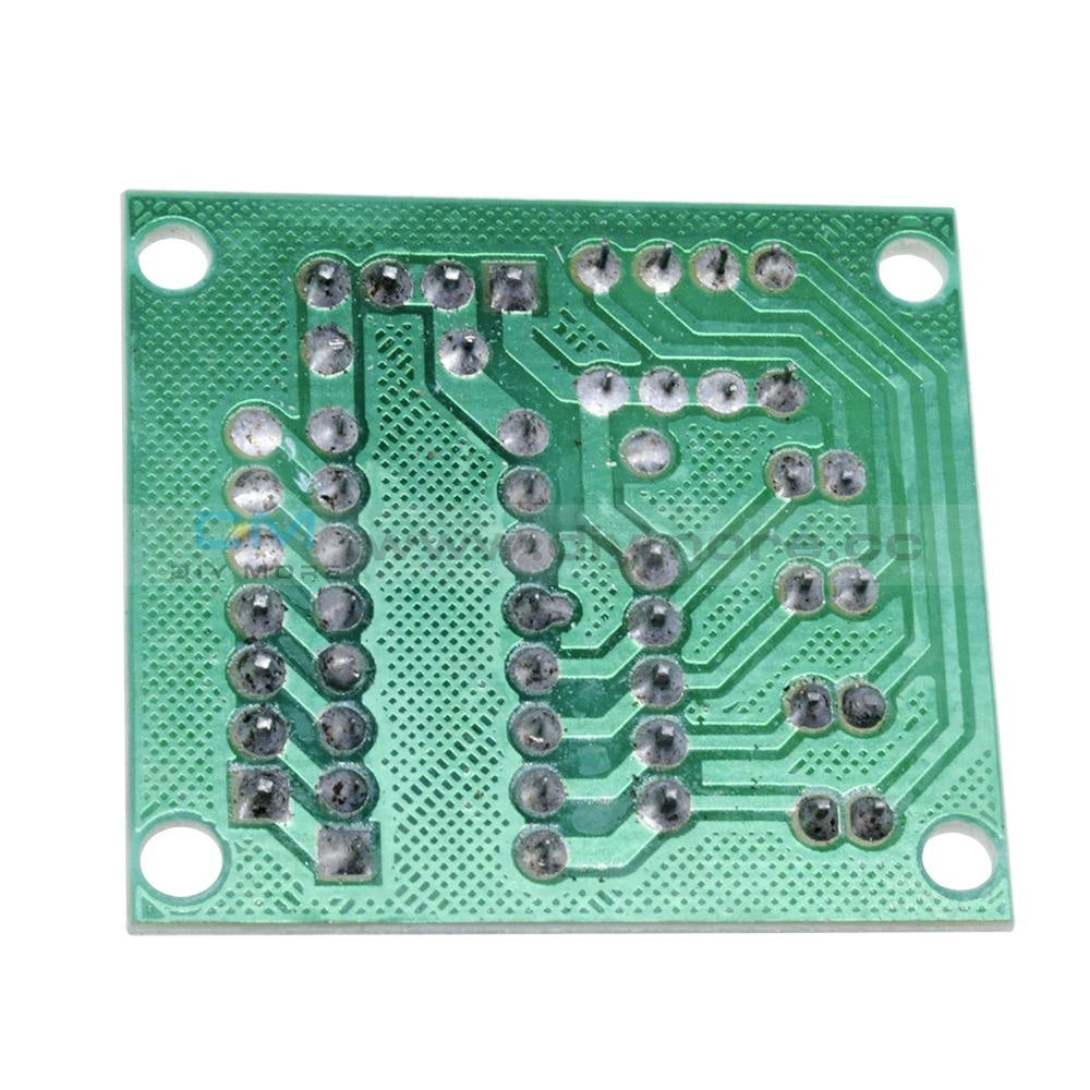
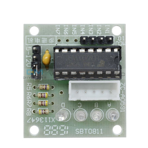 Translation missing: en.products.product.regular_price $3.99{"id":4419937927239,"title":"Dual Mode PWM PULSE Square Wave Rectangular Wave Signal Adjustable Generator Control Module DC Stepper Motor Drive Driver Board","handle":"dual-mode-pwm-pulse-square-wave-rectangular-wave-signal-adjustable-generator-control-module-dc-stepper-motor-drive-driver-board","description":"\u003cdiv\u003e\n\u003cp\u003e\u003cwidget data-widget-type=\"customText\" id=\"33684419\" title=\"Head\" type=\"custom\"\u003e\u003c\/widget\u003e\u003c\/p\u003e\n\u003cp\u003e \u003c\/p\u003e\n\u003cp\u003e\u003cimg src=\"https:\/\/ae01.alicdn.com\/kf\/HTB12JMgilsmBKNjSZFsq6yXSVXaS.jpg\"\u003e\u003c\/p\u003e\n\u003cp\u003e \u003c\/p\u003e\n\u003cp style='box-sizing:content-box;font-size:13px;border-top:0px;font-family:\"Open Sans\", Arial, Helvetica, sans-serif, SimSun, 宋体;border-right:0px;vertical-align:baseline;white-space:normal;word-spacing:0px;border-bottom:0px;text-transform:none;font-weight:400;color:#000000;padding-bottom:0px;font-style:normal;padding-top:0px;padding-left:0px;margin:0px;border-left:0px;orphans:2;widows:2;letter-spacing:normal;padding-right:0px;background-color:#FFFFFF;text-indent:0px;font-variant-ligatures:normal;font-variant-caps:normal;font-variant-numeric:inherit;font-variant-east-asian:inherit;font-stretch:inherit;-webkit-text-stroke-width:0px;text-decoration-style:initial;text-decoration-color:initial;'\u003e\u003cspan style='box-sizing:content-box;font-size:18px;border-top:0px;font-family:\"Trebuchet MS\";border-right:0px;vertical-align:baseline;border-bottom:0px;padding-bottom:0px;padding-top:0px;padding-left:0px;margin:0px;border-left:0px;padding-right:0px;font-stretch:inherit;' data-spm-anchor-id=\"2114.10010108.1000023.i0.70637de6zbrpaz\"\u003e1.PWM signal generator, square wave rectangular wave signal generator\u003c\/span\u003e\u003c\/p\u003e\n\u003cp style='box-sizing:content-box;font-size:13px;border-top:0px;font-family:\"Open Sans\", Arial, Helvetica, sans-serif, SimSun, 宋体;border-right:0px;vertical-align:baseline;white-space:normal;word-spacing:0px;border-bottom:0px;text-transform:none;font-weight:400;color:#000000;padding-bottom:0px;font-style:normal;padding-top:0px;padding-left:0px;margin:0px;border-left:0px;orphans:2;widows:2;letter-spacing:normal;padding-right:0px;background-color:#FFFFFF;text-indent:0px;font-variant-ligatures:normal;font-variant-caps:normal;font-variant-numeric:inherit;font-variant-east-asian:inherit;font-stretch:inherit;-webkit-text-stroke-width:0px;text-decoration-style:initial;text-decoration-color:initial;'\u003e\u003cspan style='box-sizing:content-box;font-size:18px;border-top:0px;font-family:\"Trebuchet MS\";border-right:0px;vertical-align:baseline;border-bottom:0px;padding-bottom:0px;padding-top:0px;padding-left:0px;margin:0px;border-left:0px;padding-right:0px;font-stretch:inherit;'\u003e2. Used to generate square wave rectangular wave signals for controlling DC motor or stepper motor driver; used for servo motor, stepping motor, electric gripper, replacing PLC pulse, etc.\u003c\/span\u003e\u003c\/p\u003e\n\u003cp style='box-sizing:content-box;font-size:13px;border-top:0px;font-family:\"Open Sans\", Arial, Helvetica, sans-serif, SimSun, 宋体;border-right:0px;vertical-align:baseline;white-space:normal;word-spacing:0px;border-bottom:0px;text-transform:none;font-weight:400;color:#000000;padding-bottom:0px;font-style:normal;padding-top:0px;padding-left:0px;margin:0px;border-left:0px;orphans:2;widows:2;letter-spacing:normal;padding-right:0px;background-color:#FFFFFF;text-indent:0px;font-variant-ligatures:normal;font-variant-caps:normal;font-variant-numeric:inherit;font-variant-east-asian:inherit;font-stretch:inherit;-webkit-text-stroke-width:0px;text-decoration-style:initial;text-decoration-color:initial;'\u003e\u003cspan style='box-sizing:content-box;font-size:18px;border-top:0px;font-family:\"Trebuchet MS\";border-right:0px;vertical-align:baseline;border-bottom:0px;padding-bottom:0px;padding-top:0px;padding-left:0px;margin:0px;border-left:0px;padding-right:0px;font-stretch:inherit;'\u003e3. The supporting driver realizes dimming, speed regulation, control of solenoid valve, etc., but can not directly drive the load of the electric motor solenoid valve.\u003c\/span\u003e\u003c\/p\u003e\n\u003cp style='box-sizing:content-box;font-size:13px;border-top:0px;font-family:\"Open Sans\", Arial, Helvetica, sans-serif, SimSun, 宋体;border-right:0px;vertical-align:baseline;white-space:normal;word-spacing:0px;border-bottom:0px;text-transform:none;font-weight:400;color:#000000;padding-bottom:0px;font-style:normal;padding-top:0px;padding-left:0px;margin:0px;border-left:0px;orphans:2;widows:2;letter-spacing:normal;padding-right:0px;background-color:#FFFFFF;text-indent:0px;font-variant-ligatures:normal;font-variant-caps:normal;font-variant-numeric:inherit;font-variant-east-asian:inherit;font-stretch:inherit;-webkit-text-stroke-width:0px;text-decoration-style:initial;text-decoration-color:initial;'\u003e\u003cspan style='box-sizing:content-box;font-size:18px;border-top:0px;font-family:\"Trebuchet MS\";border-right:0px;vertical-align:baseline;border-bottom:0px;padding-bottom:0px;padding-top:0px;padding-left:0px;margin:0px;border-left:0px;padding-right:0px;font-stretch:inherit;'\u003e\u003c\/span\u003e \u003c\/p\u003e\n\u003cp style='box-sizing:content-box;font-size:13px;border-top:0px;font-family:\"Open Sans\", Arial, Helvetica, sans-serif, SimSun, 宋体;border-right:0px;vertical-align:baseline;white-space:normal;word-spacing:0px;border-bottom:0px;text-transform:none;font-weight:400;color:#000000;padding-bottom:0px;font-style:normal;padding-top:0px;padding-left:0px;margin:0px;border-left:0px;orphans:2;widows:2;letter-spacing:normal;padding-right:0px;background-color:#FFFFFF;text-indent:0px;font-variant-ligatures:normal;font-variant-caps:normal;font-variant-numeric:inherit;font-variant-east-asian:inherit;font-stretch:inherit;-webkit-text-stroke-width:0px;text-decoration-style:initial;text-decoration-color:initial;'\u003e\u003cspan style='box-sizing:content-box;font-size:18px;border-top:0px;font-family:\"Trebuchet MS\";border-right:0px;vertical-align:baseline;border-bottom:0px;color:#FF0000;padding-bottom:0px;padding-top:0px;padding-left:0px;margin:0px;border-left:0px;padding-right:0px;font-stretch:inherit;'\u003e1. Product Highlights:\u003c\/span\u003e\u003cbr style=\"box-sizing:content-box;\"\u003e\u003cspan style='box-sizing:content-box;font-size:18px;border-top:0px;font-family:\"Trebuchet MS\";border-right:0px;vertical-align:baseline;border-bottom:0px;padding-bottom:0px;padding-top:0px;padding-left:0px;margin:0px;border-left:0px;padding-right:0px;font-stretch:inherit;'\u003e1.1 Two modes can be selected:\u003c\/span\u003e\u003cbr style=\"box-sizing:content-box;\"\u003e\u003cspan style='box-sizing:content-box;font-size:18px;border-top:0px;font-family:\"Trebuchet MS\";border-right:0px;vertical-align:baseline;border-bottom:0px;padding-bottom:0px;padding-top:0px;padding-left:0px;margin:0px;border-left:0px;padding-right:0px;font-stretch:inherit;'\u003ePWM mode - frequency (continuous), duty cycle, pulse number adjustable;\u003c\/span\u003e\u003cbr style=\"box-sizing:content-box;\"\u003e\u003cspan style='box-sizing:content-box;font-size:18px;border-top:0px;font-family:\"Trebuchet MS\";border-right:0px;vertical-align:baseline;border-bottom:0px;padding-bottom:0px;padding-top:0px;padding-left:0px;margin:0px;border-left:0px;padding-right:0px;font-stretch:inherit;'\u003ePULSE pulse mode - positive pulse width time, negative pulse width time, delay start time, and number of pulses are adjustable.\u003c\/span\u003e\u003cbr style=\"box-sizing:content-box;\"\u003e\u003cspan style='box-sizing:content-box;font-size:18px;border-top:0px;font-family:\"Trebuchet MS\";border-right:0px;vertical-align:baseline;border-bottom:0px;padding-bottom:0px;padding-top:0px;padding-left:0px;margin:0px;border-left:0px;padding-right:0px;font-stretch:inherit;'\u003e1.2 With start and stop button, can control the output and stop of the signal\u003c\/span\u003e\u003cbr style=\"box-sizing:content-box;\"\u003e\u003cspan style='box-sizing:content-box;font-size:18px;border-top:0px;font-family:\"Trebuchet MS\";border-right:0px;vertical-align:baseline;border-bottom:0px;padding-bottom:0px;padding-top:0px;padding-left:0px;margin:0px;border-left:0px;padding-right:0px;font-stretch:inherit;'\u003e1.3 Wide voltage input 3.3-30V, with anti-reverse protection, 5.08mm terminal wiring\u003c\/span\u003e\u003c\/p\u003e\n\u003cp\u003e\u003cbr style='box-sizing:content-box;font-size:13px;font-family:\"Open Sans\", Arial, Helvetica, sans-serif, SimSun, 宋体;white-space:normal;word-spacing:0px;text-transform:none;font-weight:400;color:#000000;font-style:normal;orphans:2;widows:2;letter-spacing:normal;background-color:#FFFFFF;text-indent:0px;font-variant-ligatures:normal;font-variant-caps:normal;-webkit-text-stroke-width:0px;text-decoration-style:initial;text-decoration-color:initial;'\u003e\u003cspan style='box-sizing:content-box;font-size:18px;border-top:0px;font-family:\"Trebuchet MS\";border-right:0px;vertical-align:baseline;white-space:normal;word-spacing:0px;border-bottom:0px;text-transform:none;font-weight:400;color:#FF0000;padding-bottom:0px;font-style:normal;padding-top:0px;padding-left:0px;margin:0px;border-left:0px;orphans:2;widows:2;letter-spacing:normal;padding-right:0px;background-color:#FFFFFF;text-indent:0px;font-variant-ligatures:normal;font-variant-caps:normal;font-variant-numeric:inherit;font-variant-east-asian:inherit;font-stretch:inherit;-webkit-text-stroke-width:0px;text-decoration-style:initial;text-decoration-color:initial;'\u003e2. Technical parameters:\u003c\/span\u003e\u003cbr style='box-sizing:content-box;font-size:13px;font-family:\"Open Sans\", Arial, Helvetica, sans-serif, SimSun, 宋体;white-space:normal;word-spacing:0px;text-transform:none;font-weight:400;color:#000000;font-style:normal;orphans:2;widows:2;letter-spacing:normal;background-color:#FFFFFF;text-indent:0px;font-variant-ligatures:normal;font-variant-caps:normal;-webkit-text-stroke-width:0px;text-decoration-style:initial;text-decoration-color:initial;'\u003e\u003cspan style='box-sizing:content-box;font-size:18px;border-top:0px;font-family:\"Trebuchet MS\";border-right:0px;vertical-align:baseline;white-space:normal;word-spacing:0px;border-bottom:0px;text-transform:none;font-weight:400;color:#000000;padding-bottom:0px;font-style:normal;padding-top:0px;padding-left:0px;margin:0px;border-left:0px;orphans:2;widows:2;letter-spacing:normal;padding-right:0px;background-color:#FFFFFF;text-indent:0px;font-variant-ligatures:normal;font-variant-caps:normal;font-variant-numeric:inherit;font-variant-east-asian:inherit;font-stretch:inherit;-webkit-text-stroke-width:0px;text-decoration-style:initial;text-decoration-color:initial;'\u003e2.1 Working voltage: 3.3~30V, with anti-reverse protection\u003c\/span\u003e\u003cbr style='box-sizing:content-box;font-size:13px;font-family:\"Open Sans\", Arial, Helvetica, sans-serif, SimSun, 宋体;white-space:normal;word-spacing:0px;text-transform:none;font-weight:400;color:#000000;font-style:normal;orphans:2;widows:2;letter-spacing:normal;background-color:#FFFFFF;text-indent:0px;font-variant-ligatures:normal;font-variant-caps:normal;-webkit-text-stroke-width:0px;text-decoration-style:initial;text-decoration-color:initial;'\u003e\u003cspan style='box-sizing:content-box;font-size:18px;border-top:0px;font-family:\"Trebuchet MS\";border-right:0px;vertical-align:baseline;white-space:normal;word-spacing:0px;border-bottom:0px;text-transform:none;font-weight:400;color:#000000;padding-bottom:0px;font-style:normal;padding-top:0px;padding-left:0px;margin:0px;border-left:0px;orphans:2;widows:2;letter-spacing:normal;padding-right:0px;background-color:#FFFFFF;text-indent:0px;font-variant-ligatures:normal;font-variant-caps:normal;font-variant-numeric:inherit;font-variant-east-asian:inherit;font-stretch:inherit;-webkit-text-stroke-width:0px;text-decoration-style:initial;text-decoration-color:initial;'\u003e2.2 Frequency range: 1Hz~150KHz, accuracy about 2%\u003c\/span\u003e\u003cbr style='box-sizing:content-box;font-size:13px;font-family:\"Open Sans\", Arial, Helvetica, sans-serif, SimSun, 宋体;white-space:normal;word-spacing:0px;text-transform:none;font-weight:400;color:#000000;font-style:normal;orphans:2;widows:2;letter-spacing:normal;background-color:#FFFFFF;text-indent:0px;font-variant-ligatures:normal;font-variant-caps:normal;-webkit-text-stroke-width:0px;text-decoration-style:initial;text-decoration-color:initial;'\u003e\u003cspan style='box-sizing:content-box;font-size:18px;border-top:0px;font-family:\"Trebuchet MS\";border-right:0px;vertical-align:baseline;white-space:normal;word-spacing:0px;border-bottom:0px;text-transform:none;font-weight:400;color:#000000;padding-bottom:0px;font-style:normal;padding-top:0px;padding-left:0px;margin:0px;border-left:0px;orphans:2;widows:2;letter-spacing:normal;padding-right:0px;background-color:#FFFFFF;text-indent:0px;font-variant-ligatures:normal;font-variant-caps:normal;font-variant-numeric:inherit;font-variant-east-asian:inherit;font-stretch:inherit;-webkit-text-stroke-width:0px;text-decoration-style:initial;text-decoration-color:initial;'\u003e2.3 duty cycle range: 0-100%, 1% stepping\u003c\/span\u003e\u003cbr style='box-sizing:content-box;font-size:13px;font-family:\"Open Sans\", Arial, Helvetica, sans-serif, SimSun, 宋体;white-space:normal;word-spacing:0px;text-transform:none;font-weight:400;color:#000000;font-style:normal;orphans:2;widows:2;letter-spacing:normal;background-color:#FFFFFF;text-indent:0px;font-variant-ligatures:normal;font-variant-caps:normal;-webkit-text-stroke-width:0px;text-decoration-style:initial;text-decoration-color:initial;'\u003e\u003cspan style='box-sizing:content-box;font-size:18px;border-top:0px;font-family:\"Trebuchet MS\";border-right:0px;vertical-align:baseline;white-space:normal;word-spacing:0px;border-bottom:0px;text-transform:none;font-weight:400;color:#000000;padding-bottom:0px;font-style:normal;padding-top:0px;padding-left:0px;margin:0px;border-left:0px;orphans:2;widows:2;letter-spacing:normal;padding-right:0px;background-color:#FFFFFF;text-indent:0px;font-variant-ligatures:normal;font-variant-caps:normal;font-variant-numeric:inherit;font-variant-east-asian:inherit;font-stretch:inherit;-webkit-text-stroke-width:0px;text-decoration-style:initial;text-decoration-color:initial;'\u003e2.4 number of pulses: 1-9999, or infinite (display ‘----' stands for infinity)\u003c\/span\u003e\u003cbr style='box-sizing:content-box;font-size:13px;font-family:\"Open Sans\", Arial, Helvetica, sans-serif, SimSun, 宋体;white-space:normal;word-spacing:0px;text-transform:none;font-weight:400;color:#000000;font-style:normal;orphans:2;widows:2;letter-spacing:normal;background-color:#FFFFFF;text-indent:0px;font-variant-ligatures:normal;font-variant-caps:normal;-webkit-text-stroke-width:0px;text-decoration-style:initial;text-decoration-color:initial;'\u003e\u003cspan style='box-sizing:content-box;font-size:18px;border-top:0px;font-family:\"Trebuchet MS\";border-right:0px;vertical-align:baseline;white-space:normal;word-spacing:0px;border-bottom:0px;text-transform:none;font-weight:400;color:#000000;padding-bottom:0px;font-style:normal;padding-top:0px;padding-left:0px;margin:0px;border-left:0px;orphans:2;widows:2;letter-spacing:normal;padding-right:0px;background-color:#FFFFFF;text-indent:0px;font-variant-ligatures:normal;font-variant-caps:normal;font-variant-numeric:inherit;font-variant-east-asian:inherit;font-stretch:inherit;-webkit-text-stroke-width:0px;text-decoration-style:initial;text-decoration-color:initial;'\u003e2.5 delay output time: 0.000s-9999s, the minimum can be set 1ms\u003c\/span\u003e\u003cbr style='box-sizing:content-box;font-size:13px;font-family:\"Open Sans\", Arial, Helvetica, sans-serif, SimSun, 宋体;white-space:normal;word-spacing:0px;text-transform:none;font-weight:400;color:#000000;font-style:normal;orphans:2;widows:2;letter-spacing:normal;background-color:#FFFFFF;text-indent:0px;font-variant-ligatures:normal;font-variant-caps:normal;-webkit-text-stroke-width:0px;text-decoration-style:initial;text-decoration-color:initial;'\u003e\u003cspan style='box-sizing:content-box;font-size:18px;border-top:0px;font-family:\"Trebuchet MS\";border-right:0px;vertical-align:baseline;white-space:normal;word-spacing:0px;border-bottom:0px;text-transform:none;font-weight:400;color:#000000;padding-bottom:0px;font-style:normal;padding-top:0px;padding-left:0px;margin:0px;border-left:0px;orphans:2;widows:2;letter-spacing:normal;padding-right:0px;background-color:#FFFFFF;text-indent:0px;font-variant-ligatures:normal;font-variant-caps:normal;font-variant-numeric:inherit;font-variant-east-asian:inherit;font-stretch:inherit;-webkit-text-stroke-width:0px;text-decoration-style:initial;text-decoration-color:initial;'\u003e2.6 positive and negative pulse width length: 0.000s-9999s, the minimum can be set 1ms\u003c\/span\u003e\u003cbr style='box-sizing:content-box;font-size:13px;font-family:\"Open Sans\", Arial, Helvetica, sans-serif, SimSun, 宋体;white-space:normal;word-spacing:0px;text-transform:none;font-weight:400;color:#000000;font-style:normal;orphans:2;widows:2;letter-spacing:normal;background-color:#FFFFFF;text-indent:0px;font-variant-ligatures:normal;font-variant-caps:normal;-webkit-text-stroke-width:0px;text-decoration-style:initial;text-decoration-color:initial;'\u003e\u003cspan style='box-sizing:content-box;font-size:18px;border-top:0px;font-family:\"Trebuchet MS\";border-right:0px;vertical-align:baseline;white-space:normal;word-spacing:0px;border-bottom:0px;text-transform:none;font-weight:400;color:#000000;padding-bottom:0px;font-style:normal;padding-top:0px;padding-left:0px;margin:0px;border-left:0px;orphans:2;widows:2;letter-spacing:normal;padding-right:0px;background-color:#FFFFFF;text-indent:0px;font-variant-ligatures:normal;font-variant-caps:normal;font-variant-numeric:inherit;font-variant-east-asian:inherit;font-stretch:inherit;-webkit-text-stroke-width:0px;text-decoration-style:initial;text-decoration-color:initial;'\u003e2.7 signal loading capacity: less than 30mA\u003c\/span\u003e\u003cbr style='box-sizing:content-box;font-size:13px;font-family:\"Open Sans\", Arial, Helvetica, sans-serif, SimSun, 宋体;white-space:normal;word-spacing:0px;text-transform:none;font-weight:400;color:#000000;font-style:normal;orphans:2;widows:2;letter-spacing:normal;background-color:#FFFFFF;text-indent:0px;font-variant-ligatures:normal;font-variant-caps:normal;-webkit-text-stroke-width:0px;text-decoration-style:initial;text-decoration-color:initial;'\u003e\u003cspan style='box-sizing:content-box;font-size:18px;border-top:0px;font-family:\"Trebuchet MS\";border-right:0px;vertical-align:baseline;white-space:normal;word-spacing:0px;border-bottom:0px;text-transform:none;font-weight:400;color:#000000;padding-bottom:0px;font-style:normal;padding-top:0px;padding-left:0px;margin:0px;border-left:0px;orphans:2;widows:2;letter-spacing:normal;padding-right:0px;background-color:#FFFFFF;text-indent:0px;font-variant-ligatures:normal;font-variant-caps:normal;font-variant-numeric:inherit;font-variant-east-asian:inherit;font-stretch:inherit;-webkit-text-stroke-width:0px;text-decoration-style:initial;text-decoration-color:initial;'\u003e2.8 Output signal amplitude: amplitude is equal to the supply voltage\u003c\/span\u003e\u003cbr style='box-sizing:content-box;font-size:13px;font-family:\"Open Sans\", Arial, Helvetica, sans-serif, SimSun, 宋体;white-space:normal;word-spacing:0px;text-transform:none;font-weight:400;color:#000000;font-style:normal;orphans:2;widows:2;letter-spacing:normal;background-color:#FFFFFF;text-indent:0px;font-variant-ligatures:normal;font-variant-caps:normal;-webkit-text-stroke-width:0px;text-decoration-style:initial;text-decoration-color:initial;'\u003e\u003cspan style='box-sizing:content-box;font-size:18px;border-top:0px;font-family:\"Trebuchet MS\";border-right:0px;vertical-align:baseline;white-space:normal;word-spacing:0px;border-bottom:0px;text-transform:none;font-weight:400;color:#000000;padding-bottom:0px;font-style:normal;padding-top:0px;padding-left:0px;margin:0px;border-left:0px;orphans:2;widows:2;letter-spacing:normal;padding-right:0px;background-color:#FFFFFF;text-indent:0px;font-variant-ligatures:normal;font-variant-caps:normal;font-variant-numeric:inherit;font-variant-east-asian:inherit;font-stretch:inherit;-webkit-text-stroke-width:0px;text-decoration-style:initial;text-decoration-color:initial;'\u003e2.9 Product size: 60mm*32mm*10mm\u003c\/span\u003e\u003cbr style='box-sizing:content-box;font-size:13px;font-family:\"Open Sans\", Arial, Helvetica, sans-serif, SimSun, 宋体;white-space:normal;word-spacing:0px;text-transform:none;font-weight:400;color:#000000;font-style:normal;orphans:2;widows:2;letter-spacing:normal;background-color:#FFFFFF;text-indent:0px;font-variant-ligatures:normal;font-variant-caps:normal;-webkit-text-stroke-width:0px;text-decoration-style:initial;text-decoration-color:initial;'\u003e\u003cspan style='box-sizing:content-box;font-size:18px;border-top:0px;font-family:\"Trebuchet MS\";border-right:0px;vertical-align:baseline;white-space:normal;word-spacing:0px;border-bottom:0px;text-transform:none;font-weight:400;color:#000000;padding-bottom:0px;font-style:normal;padding-top:0px;padding-left:0px;margin:0px;border-left:0px;orphans:2;widows:2;letter-spacing:normal;padding-right:0px;background-color:#FFFFFF;text-indent:0px;font-variant-ligatures:normal;font-variant-caps:normal;font-variant-numeric:inherit;font-variant-east-asian:inherit;font-stretch:inherit;-webkit-text-stroke-width:0px;text-decoration-style:initial;text-decoration-color:initial;'\u003e2.10 Product Weight: 18g\u003c\/span\u003e\u003cbr style='box-sizing:content-box;font-size:13px;font-family:\"Open Sans\", Arial, Helvetica, sans-serif, SimSun, 宋体;white-space:normal;word-spacing:0px;text-transform:none;font-weight:400;color:#000000;font-style:normal;orphans:2;widows:2;letter-spacing:normal;background-color:#FFFFFF;text-indent:0px;font-variant-ligatures:normal;font-variant-caps:normal;-webkit-text-stroke-width:0px;text-decoration-style:initial;text-decoration-color:initial;'\u003e\u003cspan style='box-sizing:content-box;font-size:18px;border-top:0px;font-family:\"Trebuchet MS\";border-right:0px;vertical-align:baseline;white-space:normal;word-spacing:0px;border-bottom:0px;text-transform:none;font-weight:400;color:#000000;padding-bottom:0px;font-style:normal;padding-top:0px;padding-left:0px;margin:0px;border-left:0px;orphans:2;widows:2;letter-spacing:normal;padding-right:0px;background-color:#FFFFFF;text-indent:0px;font-variant-ligatures:normal;font-variant-caps:normal;font-variant-numeric:inherit;font-variant-east-asian:inherit;font-stretch:inherit;-webkit-text-stroke-width:0px;text-decoration-style:initial;text-decoration-color:initial;'\u003e2.11 Packing: Anti-static bag\u003c\/span\u003e\u003cspan style='font-size:13px;font-family:\"Open Sans\", Arial, Helvetica, sans-serif, SimSun, 宋体;white-space:normal;word-spacing:0px;text-transform:none;float:none;font-weight:400;color:#000000;font-style:normal;orphans:2;widows:2;display:inline !important;letter-spacing:normal;background-color:#FFFFFF;text-indent:0px;font-variant-ligatures:normal;font-variant-caps:normal;-webkit-text-stroke-width:0px;text-decoration-style:initial;text-decoration-color:initial;'\u003e\u003c\/span\u003e\u003c\/p\u003e\n\u003cp style='box-sizing:content-box;font-size:13px;border-top:0px;font-family:\"Open Sans\", Arial, Helvetica, sans-serif, SimSun, 宋体;border-right:0px;vertical-align:baseline;white-space:normal;word-spacing:0px;border-bottom:0px;text-transform:none;font-weight:400;color:#000000;padding-bottom:0px;font-style:normal;padding-top:0px;padding-left:0px;margin:0px;border-left:0px;orphans:2;widows:2;letter-spacing:normal;padding-right:0px;background-color:#FFFFFF;text-indent:0px;font-variant-ligatures:normal;font-variant-caps:normal;font-variant-numeric:inherit;font-variant-east-asian:inherit;font-stretch:inherit;-webkit-text-stroke-width:0px;text-decoration-style:initial;text-decoration-color:initial;'\u003e\u003cspan style='box-sizing:content-box;font-size:18px;border-top:0px;font-family:\"Trebuchet MS\";border-right:0px;vertical-align:baseline;border-bottom:0px;padding-bottom:0px;padding-top:0px;padding-left:0px;margin:0px;border-left:0px;padding-right:0px;font-stretch:inherit;'\u003e\u003c\/span\u003e \u003c\/p\u003e\n\u003cp style='box-sizing:content-box;font-size:13px;border-top:0px;font-family:\"Open Sans\", Arial, Helvetica, sans-serif, SimSun, 宋体;border-right:0px;vertical-align:baseline;white-space:normal;word-spacing:0px;border-bottom:0px;text-transform:none;font-weight:400;color:#000000;padding-bottom:0px;font-style:normal;padding-top:0px;padding-left:0px;margin:0px;border-left:0px;orphans:2;widows:2;letter-spacing:normal;padding-right:0px;background-color:#FFFFFF;text-indent:0px;font-variant-ligatures:normal;font-variant-caps:normal;font-variant-numeric:inherit;font-variant-east-asian:inherit;font-stretch:inherit;-webkit-text-stroke-width:0px;text-decoration-style:initial;text-decoration-color:initial;'\u003e\u003cspan style='box-sizing:content-box;font-size:18px;border-top:0px;font-family:\"Trebuchet MS\";border-right:0px;vertical-align:baseline;border-bottom:0px;color:#FF0000;padding-bottom:0px;padding-top:0px;padding-left:0px;margin:0px;border-left:0px;padding-right:0px;font-stretch:inherit;'\u003e3. PWM mode (display has \"%\" for PWM mode)\u003c\/span\u003e\u003c\/p\u003e\n\u003cp style='box-sizing:content-box;font-size:13px;border-top:0px;font-family:\"Open Sans\", Arial, Helvetica, sans-serif, SimSun, 宋体;border-right:0px;vertical-align:baseline;white-space:normal;word-spacing:0px;border-bottom:0px;text-transform:none;font-weight:400;color:#000000;padding-bottom:0px;font-style:normal;padding-top:0px;padding-left:0px;margin:0px;border-left:0px;orphans:2;widows:2;letter-spacing:normal;padding-right:0px;background-color:#FFFFFF;text-indent:0px;font-variant-ligatures:normal;font-variant-caps:normal;font-variant-numeric:inherit;font-variant-east-asian:inherit;font-stretch:inherit;-webkit-text-stroke-width:0px;text-decoration-style:initial;text-decoration-color:initial;'\u003e\u003cspan style='box-sizing:content-box;font-size:18px;border-top:0px;font-family:\"Trebuchet MS\";border-right:0px;vertical-align:baseline;border-bottom:0px;padding-bottom:0px;padding-top:0px;padding-left:0px;margin:0px;border-left:0px;padding-right:0px;font-stretch:inherit;'\u003eThe factory default mode is PWM mode, FREQ+ and FREQ-key set frequency, DUTY+ and DUTY-button set duty cycle; short press STOP button control signal output or stop, stop output is 0, the screen displays “OUT” mark as There is output, otherwise it stops output; the default factory frequency is 1KHZ and the duty cycle is 50%.\u003c\/span\u003e\u003c\/p\u003e\n\u003cp style='box-sizing:content-box;font-size:13px;border-top:0px;font-family:\"Open Sans\", Arial, Helvetica, sans-serif, SimSun, 宋体;border-right:0px;vertical-align:baseline;white-space:normal;word-spacing:0px;border-bottom:0px;text-transform:none;font-weight:400;color:#000000;padding-bottom:0px;font-style:normal;padding-top:0px;padding-left:0px;margin:0px;border-left:0px;orphans:2;widows:2;letter-spacing:normal;padding-right:0px;background-color:#FFFFFF;text-indent:0px;font-variant-ligatures:normal;font-variant-caps:normal;font-variant-numeric:inherit;font-variant-east-asian:inherit;font-stretch:inherit;-webkit-text-stroke-width:0px;text-decoration-style:initial;text-decoration-color:initial;'\u003e\u003cspan style='box-sizing:content-box;font-size:18px;border-top:0px;font-family:\"Trebuchet MS\";border-right:0px;vertical-align:baseline;border-bottom:0px;padding-bottom:0px;padding-top:0px;padding-left:0px;margin:0px;border-left:0px;padding-right:0px;font-stretch:inherit;'\u003eIf you want to switch to PULSE pulse mode, long press the SET button (more than 6 seconds), do not release, you will see the screen change, \"%\" disappears, it is PULSE mode.\u003c\/span\u003e\u003c\/p\u003e\n\u003cp style='box-sizing:content-box;font-size:13px;border-top:0px;font-family:\"Open Sans\", Arial, Helvetica, sans-serif, SimSun, 宋体;border-right:0px;vertical-align:baseline;white-space:normal;word-spacing:0px;border-bottom:0px;text-transform:none;font-weight:400;color:#000000;padding-bottom:0px;font-style:normal;padding-top:0px;padding-left:0px;margin:0px;border-left:0px;orphans:2;widows:2;letter-spacing:normal;padding-right:0px;background-color:#FFFFFF;text-indent:0px;font-variant-ligatures:normal;font-variant-caps:normal;font-variant-numeric:inherit;font-variant-east-asian:inherit;font-stretch:inherit;-webkit-text-stroke-width:0px;text-decoration-style:initial;text-decoration-color:initial;'\u003e\u003cspan style='box-sizing:content-box;font-size:18px;border-top:0px;font-family:\"Trebuchet MS\";border-right:0px;vertical-align:baseline;border-bottom:0px;padding-bottom:0px;padding-top:0px;padding-left:0px;margin:0px;border-left:0px;padding-right:0px;font-stretch:inherit;'\u003e3.2 PULSE pulse mode (No \"%\" on the right side of the display is displayed in PULSE mode)\u003c\/span\u003e\u003c\/p\u003e\n\u003cp style='box-sizing:content-box;font-size:13px;border-top:0px;font-family:\"Open Sans\", Arial, Helvetica, sans-serif, SimSun, 宋体;border-right:0px;vertical-align:baseline;white-space:normal;word-spacing:0px;border-bottom:0px;text-transform:none;font-weight:400;color:#000000;padding-bottom:0px;font-style:normal;padding-top:0px;padding-left:0px;margin:0px;border-left:0px;orphans:2;widows:2;letter-spacing:normal;padding-right:0px;background-color:#FFFFFF;text-indent:0px;font-variant-ligatures:normal;font-variant-caps:normal;font-variant-numeric:inherit;font-variant-east-asian:inherit;font-stretch:inherit;-webkit-text-stroke-width:0px;text-decoration-style:initial;text-decoration-color:initial;'\u003e\u003cspan style='box-sizing:content-box;font-size:18px;border-top:0px;font-family:\"Trebuchet MS\";border-right:0px;vertical-align:baseline;border-bottom:0px;padding-bottom:0px;padding-top:0px;padding-left:0px;margin:0px;border-left:0px;padding-right:0px;font-stretch:inherit;'\u003eThe P+ and P- buttons set the positive pulse width time, the LCD screen shows up, the N+ and N- buttons set the negative pulse width time, the LCD screen displays downwards, the unit is seconds; short press the STOP button to control the signal output or stop, stop output It is 0, the screen displays “OUT” mark as output, otherwise it stops output; the default factory positive pulse width is 0.5 second, and the negative pulse width is 0.5 second.\u003c\/span\u003e\u003c\/p\u003e\n\u003cp style='box-sizing:content-box;font-size:13px;border-top:0px;font-family:\"Open Sans\", Arial, Helvetica, sans-serif, SimSun, 宋体;border-right:0px;vertical-align:baseline;white-space:normal;word-spacing:0px;border-bottom:0px;text-transform:none;font-weight:400;color:#000000;padding-bottom:0px;font-style:normal;padding-top:0px;padding-left:0px;margin:0px;border-left:0px;orphans:2;widows:2;letter-spacing:normal;padding-right:0px;background-color:#FFFFFF;text-indent:0px;font-variant-ligatures:normal;font-variant-caps:normal;font-variant-numeric:inherit;font-variant-east-asian:inherit;font-stretch:inherit;-webkit-text-stroke-width:0px;text-decoration-style:initial;text-decoration-color:initial;'\u003e\u003cspan style='box-sizing:content-box;font-size:18px;border-top:0px;font-family:\"Trebuchet MS\";border-right:0px;vertical-align:baseline;border-bottom:0px;padding-bottom:0px;padding-top:0px;padding-left:0px;margin:0px;border-left:0px;padding-right:0px;font-stretch:inherit;'\u003ePulse number and delay time setting - In PULSE mode, press and hold the SET button for 2 seconds and then release, enter the pulse number and delay time setting interface, the screen displays SET, it will be turned off and cleared after entering. Output pulse; P+ and P- buttons set delay time, N+ and N- buttons set pulse number, factory default delay time is 0 seconds, pulse number is infinite (display ----); Press the button for 2 seconds, automatically return to the pulse interface, press the STOP button, after the delay setting time, start to send the set number of pulses, if the number of pulses is sent, it will automatically output 0, if the period is not sent, press the STOP button. The output pulse will be turned off and cleared, and the number of pulses set will be issued each time it is started.\u003c\/span\u003e\u003c\/p\u003e\n\u003cp style='box-sizing:content-box;font-size:13px;border-top:0px;font-family:\"Open Sans\", Arial, Helvetica, sans-serif, SimSun, 宋体;border-right:0px;vertical-align:baseline;white-space:normal;word-spacing:0px;border-bottom:0px;text-transform:none;font-weight:400;color:#000000;padding-bottom:0px;font-style:normal;padding-top:0px;padding-left:0px;margin:0px;border-left:0px;orphans:2;widows:2;letter-spacing:normal;padding-right:0px;background-color:#FFFFFF;text-indent:0px;font-variant-ligatures:normal;font-variant-caps:normal;font-variant-numeric:inherit;font-variant-east-asian:inherit;font-stretch:inherit;-webkit-text-stroke-width:0px;text-decoration-style:initial;text-decoration-color:initial;'\u003e\u003cspan style='box-sizing:content-box;font-size:18px;border-top:0px;font-family:\"Trebuchet MS\";border-right:0px;vertical-align:baseline;border-bottom:0px;padding-bottom:0px;padding-top:0px;padding-left:0px;margin:0px;border-left:0px;padding-right:0px;font-stretch:inherit;'\u003e3.3 Application Operation Examples\u003c\/span\u003e\u003cbr style=\"box-sizing:content-box;\"\u003e\u003cspan style='box-sizing:content-box;font-size:18px;border-top:0px;font-family:\"Trebuchet MS\";border-right:0px;vertical-align:baseline;border-bottom:0px;padding-bottom:0px;padding-top:0px;padding-left:0px;margin:0px;border-left:0px;padding-right:0px;font-stretch:inherit;'\u003e3.3.1 PWM output 20KHZ, 60% duty cycle: Select PWM mode, the frequency is set to 20.00, and the duty ratio is set to 060%.\u003c\/span\u003e\u003cbr style=\"box-sizing:content-box;\"\u003e\u003cspan style='box-sizing:content-box;font-size:18px;border-top:0px;font-family:\"Trebuchet MS\";border-right:0px;vertical-align:baseline;border-bottom:0px;padding-bottom:0px;padding-top:0px;padding-left:0px;margin:0px;border-left:0px;padding-right:0px;font-stretch:inherit;'\u003e3.3.2 The output is turned on for 0.6 seconds and turned off for 0.2 seconds. Infinite loop: select PULSE mode, the positive pulse width is set to 0.600, the negative pulse width is set to 0.200, the delay time is set to 0.000, and the number of pulses is set to --- -.\u003c\/span\u003e\u003cbr style=\"box-sizing:content-box;\"\u003e\u003cspan style='box-sizing:content-box;font-size:18px;border-top:0px;font-family:\"Trebuchet MS\";border-right:0px;vertical-align:baseline;border-bottom:0px;padding-bottom:0px;padding-top:0px;padding-left:0px;margin:0px;border-left:0px;padding-right:0px;font-stretch:inherit;'\u003e3.3.3 Power on or press the start button, delay 5 seconds, then the output is turned on for 0.6 seconds, off 0.2 seconds, infinite loop: select PULSE mode, positive pulse width is set to 0.600, negative pulse width is set to 0.200, delay The time is set to 5.000 and the number of pulses is set to ----.\u003c\/span\u003e\u003cbr style=\"box-sizing:content-box;\"\u003e\u003cspan style='box-sizing:content-box;font-size:18px;border-top:0px;font-family:\"Trebuchet MS\";border-right:0px;vertical-align:baseline;border-bottom:0px;padding-bottom:0px;padding-top:0px;padding-left:0px;margin:0px;border-left:0px;padding-right:0px;font-stretch:inherit;'\u003e3.3.4 Power on or press the start button, delay 5 seconds, then output high level 10ms low level 10ms pulse 100: select PULSE mode, positive pulse width is set to 0.010, negative pulse width is set to 0.010, delay The time is set to 5.000 and the number of pulses is set to 0100.\u003c\/span\u003e\u003cbr style=\"box-sizing:content-box;\"\u003e\u003cspan style='box-sizing:content-box;font-size:18px;border-top:0px;font-family:\"Trebuchet MS\";border-right:0px;vertical-align:baseline;border-bottom:0px;padding-bottom:0px;padding-top:0px;padding-left:0px;margin:0px;border-left:0px;padding-right:0px;font-stretch:inherit;'\u003e3.3.5 Power-on delay for 10 seconds, then permanently output signal: select PULSE mode, the positive pulse width is set to a number greater than 0, the negative pulse width is set to 0, the delay time is set to 10.00 seconds, and the pulse number is infinite. (----).\u003c\/span\u003e\u003cbr style=\"box-sizing:content-box;\"\u003e\u003cspan style='box-sizing:content-box;font-size:18px;border-top:0px;font-family:\"Trebuchet MS\";border-right:0px;vertical-align:baseline;border-bottom:0px;padding-bottom:0px;padding-top:0px;padding-left:0px;margin:0px;border-left:0px;padding-right:0px;font-stretch:inherit;'\u003e3.3.6 Other applications can explore or consult customer service\u003c\/span\u003e\u003c\/p\u003e\n\u003cp style='box-sizing:content-box;font-size:13px;border-top:0px;font-family:\"Open Sans\", Arial, Helvetica, sans-serif, SimSun, 宋体;border-right:0px;vertical-align:baseline;white-space:normal;word-spacing:0px;border-bottom:0px;text-transform:none;font-weight:400;color:#000000;padding-bottom:0px;font-style:normal;padding-top:0px;padding-left:0px;margin:0px;border-left:0px;orphans:2;widows:2;letter-spacing:normal;padding-right:0px;background-color:#FFFFFF;text-indent:0px;font-variant-ligatures:normal;font-variant-caps:normal;font-variant-numeric:inherit;font-variant-east-asian:inherit;font-stretch:inherit;-webkit-text-stroke-width:0px;text-decoration-style:initial;text-decoration-color:initial;'\u003e\u003cspan style='box-sizing:content-box;font-size:18px;border-top:0px;font-family:\"Trebuchet MS\";border-right:0px;vertical-align:baseline;border-bottom:0px;padding-bottom:0px;padding-top:0px;padding-left:0px;margin:0px;border-left:0px;padding-right:0px;font-stretch:inherit;'\u003eAll setup parameters are not lost when they are turned off.\u003c\/span\u003e\u003c\/p\u003e\n\u003cp style='box-sizing:content-box;font-size:13px;border-top:0px;font-family:\"Open Sans\", Arial, Helvetica, sans-serif, SimSun, 宋体;border-right:0px;vertical-align:baseline;white-space:normal;word-spacing:0px;border-bottom:0px;text-transform:none;font-weight:400;color:#000000;padding-bottom:0px;font-style:normal;padding-top:0px;padding-left:0px;margin:0px;border-left:0px;orphans:2;widows:2;letter-spacing:normal;padding-right:0px;background-color:#FFFFFF;text-indent:0px;font-variant-ligatures:normal;font-variant-caps:normal;font-variant-numeric:inherit;font-variant-east-asian:inherit;font-stretch:inherit;-webkit-text-stroke-width:0px;text-decoration-style:initial;text-decoration-color:initial;'\u003e\u003cspan style='box-sizing:content-box;font-size:18px;border-top:0px;font-family:\"Trebuchet MS\";border-right:0px;vertical-align:baseline;border-bottom:0px;padding-bottom:0px;padding-top:0px;padding-left:0px;margin:0px;border-left:0px;padding-right:0px;font-stretch:inherit;'\u003e\u003c\/span\u003e \u003c\/p\u003e\n\u003cp style='box-sizing:content-box;font-size:13px;border-top:0px;font-family:\"Open Sans\", Arial, Helvetica, sans-serif, SimSun, 宋体;border-right:0px;vertical-align:baseline;white-space:normal;word-spacing:0px;border-bottom:0px;text-transform:none;font-weight:400;color:#000000;padding-bottom:0px;font-style:normal;padding-top:0px;padding-left:0px;margin:0px;border-left:0px;orphans:2;widows:2;letter-spacing:normal;padding-right:0px;background-color:#FFFFFF;text-indent:0px;font-variant-ligatures:normal;font-variant-caps:normal;font-variant-numeric:inherit;font-variant-east-asian:inherit;font-stretch:inherit;-webkit-text-stroke-width:0px;text-decoration-style:initial;text-decoration-color:initial;'\u003e\u003cspan style='box-sizing:content-box;font-size:18px;border-top:0px;font-family:\"Trebuchet MS\";border-right:0px;vertical-align:baseline;border-bottom:0px;padding-bottom:0px;padding-top:0px;padding-left:0px;margin:0px;border-left:0px;padding-right:0px;font-stretch:inherit;'\u003e\u003c\/span\u003e \u003c\/p\u003e\n\u003cspan style='box-sizing:content-box;font-size:18px;border-top:0px;font-family:\"Trebuchet MS\";border-right:0px;vertical-align:baseline;border-bottom:0px;padding-bottom:0px;padding-top:0px;padding-left:0px;margin:0px;border-left:0px;padding-right:0px;font-stretch:inherit;'\u003e \u003cp\u003e\u003cimg src=\"https:\/\/ae01.alicdn.com\/kf\/HTB1VXjubuUXBuNjt_a0q6AysXXaA.jpg\"\u003e\u003c\/p\u003e\n\u003cp\u003e \u003c\/p\u003e\n\u003cp\u003e\u003cimg style=\"width:1000px;\" src=\"https:\/\/ae01.alicdn.com\/kf\/HTB1_riVa2WG3KVjSZFPq6xaiXXak.jpg\"\u003e\u003c\/p\u003e\n\u003cp\u003e\u003cimg style=\"width:1000px;\" src=\"https:\/\/ae01.alicdn.com\/kf\/HTB1MxCVa.GF3KVjSZFoq6zmpFXas.jpg\"\u003e\u003c\/p\u003e\n\u003cp\u003e\u003cimg style=\"width:1000px;\" src=\"https:\/\/ae01.alicdn.com\/kf\/HTB17Z15aWSs3KVjSZPiq6AsiVXaQ.jpg\"\u003e\u003c\/p\u003e\n\u003cp\u003e\u003cimg src=\"https:\/\/ae01.alicdn.com\/kf\/HTB1Hc.uimcqBKNjSZFgq6x_kXXaq.jpg\"\u003e\u003c\/p\u003e\n\u003cp\u003e \u003c\/p\u003e\n\u003cwidget data-widget-type=\"customText\" id=\"24006699\" title=\"Related\" type=\"custom\"\u003e\u003c\/widget\u003e\r \u003cp\u003e\u003c\/p\u003e\u003c\/span\u003e \u003cp\u003e \u003cscript\u003ewindow.adminAccountId=227552571;\u003c\/script\u003e \u003c\/p\u003e\n\u003c\/div\u003e","published_at":"2019-12-27T16:27:56+08:00","created_at":"2019-12-27T16:28:04+08:00","vendor":"diymore","type":"Motor Driver Module","tags":[],"price":599,"price_min":599,"price_max":599,"available":true,"price_varies":false,"compare_at_price":470,"compare_at_price_min":470,"compare_at_price_max":470,"compare_at_price_varies":false,"variants":[{"id":31582605639751,"title":"Default Title","option1":"Default Title","option2":null,"option3":null,"sku":"X13468","requires_shipping":true,"taxable":true,"featured_image":null,"available":true,"name":"Dual Mode PWM PULSE Square Wave Rectangular Wave Signal Adjustable Generator Control Module DC Stepper Motor Drive Driver Board","public_title":null,"options":["Default Title"],"price":599,"weight":0,"compare_at_price":470,"inventory_management":null,"barcode":"","requires_selling_plan":false,"selling_plan_allocations":[],"quantity_rule":{"min":1,"max":null,"increment":1}}],"images":["\/\/www.diymore.cc\/cdn\/shop\/products\/Dual-Mode-PWM-PULSE-Square-Wave-Rectangular-Wave-Signal-Adjustable-Generator-Control-Module-DC-Stepper-Motor_865.jpg?v=1588697869","\/\/www.diymore.cc\/cdn\/shop\/products\/Dual-Mode-PWM-PULSE-Square-Wave-Rectangular-Wave-Signal-Adjustable-Generator-Control-Module-DC-Stepper-Motor_9510e498-27ea-40b5-a8e9-1a342cd00df5_557.jpg?v=1588697869","\/\/www.diymore.cc\/cdn\/shop\/products\/Dual-Mode-PWM-PULSE-Square-Wave-Rectangular-Wave-Signal-Adjustable-Generator-Control-Module-DC-Stepper-Motor_a6256ea5-3d8f-458d-b789-8601fb359396_359.jpg?v=1588697869"],"featured_image":"\/\/www.diymore.cc\/cdn\/shop\/products\/Dual-Mode-PWM-PULSE-Square-Wave-Rectangular-Wave-Signal-Adjustable-Generator-Control-Module-DC-Stepper-Motor_865.jpg?v=1588697869","options":["Title"],"media":[{"alt":"Dual Mode Pwm Pulse Square Wave Rectangular Signal Adjustable Generator Control Module Dc Stepper","id":6682314965063,"position":1,"preview_image":{"aspect_ratio":1.0,"height":1000,"width":1000,"src":"\/\/www.diymore.cc\/cdn\/shop\/products\/Dual-Mode-PWM-PULSE-Square-Wave-Rectangular-Wave-Signal-Adjustable-Generator-Control-Module-DC-Stepper-Motor_865.jpg?v=1588697869"},"aspect_ratio":1.0,"height":1000,"media_type":"image","src":"\/\/www.diymore.cc\/cdn\/shop\/products\/Dual-Mode-PWM-PULSE-Square-Wave-Rectangular-Wave-Signal-Adjustable-Generator-Control-Module-DC-Stepper-Motor_865.jpg?v=1588697869","width":1000},{"alt":"Dual Mode Pwm Pulse Square Wave Rectangular Signal Adjustable Generator Control Module Dc Stepper","id":6682315227207,"position":2,"preview_image":{"aspect_ratio":1.0,"height":1000,"width":1000,"src":"\/\/www.diymore.cc\/cdn\/shop\/products\/Dual-Mode-PWM-PULSE-Square-Wave-Rectangular-Wave-Signal-Adjustable-Generator-Control-Module-DC-Stepper-Motor_9510e498-27ea-40b5-a8e9-1a342cd00df5_557.jpg?v=1588697869"},"aspect_ratio":1.0,"height":1000,"media_type":"image","src":"\/\/www.diymore.cc\/cdn\/shop\/products\/Dual-Mode-PWM-PULSE-Square-Wave-Rectangular-Wave-Signal-Adjustable-Generator-Control-Module-DC-Stepper-Motor_9510e498-27ea-40b5-a8e9-1a342cd00df5_557.jpg?v=1588697869","width":1000},{"alt":"Dual Mode Pwm Pulse Square Wave Rectangular Signal Adjustable Generator Control Module Dc Stepper","id":6682315292743,"position":3,"preview_image":{"aspect_ratio":1.0,"height":1000,"width":1000,"src":"\/\/www.diymore.cc\/cdn\/shop\/products\/Dual-Mode-PWM-PULSE-Square-Wave-Rectangular-Wave-Signal-Adjustable-Generator-Control-Module-DC-Stepper-Motor_a6256ea5-3d8f-458d-b789-8601fb359396_359.jpg?v=1588697869"},"aspect_ratio":1.0,"height":1000,"media_type":"image","src":"\/\/www.diymore.cc\/cdn\/shop\/products\/Dual-Mode-PWM-PULSE-Square-Wave-Rectangular-Wave-Signal-Adjustable-Generator-Control-Module-DC-Stepper-Motor_a6256ea5-3d8f-458d-b789-8601fb359396_359.jpg?v=1588697869","width":1000}],"requires_selling_plan":false,"selling_plan_groups":[],"content":"\u003cdiv\u003e\n\u003cp\u003e\u003cwidget data-widget-type=\"customText\" id=\"33684419\" title=\"Head\" type=\"custom\"\u003e\u003c\/widget\u003e\u003c\/p\u003e\n\u003cp\u003e \u003c\/p\u003e\n\u003cp\u003e\u003cimg src=\"https:\/\/ae01.alicdn.com\/kf\/HTB12JMgilsmBKNjSZFsq6yXSVXaS.jpg\"\u003e\u003c\/p\u003e\n\u003cp\u003e \u003c\/p\u003e\n\u003cp style='box-sizing:content-box;font-size:13px;border-top:0px;font-family:\"Open Sans\", Arial, Helvetica, sans-serif, SimSun, 宋体;border-right:0px;vertical-align:baseline;white-space:normal;word-spacing:0px;border-bottom:0px;text-transform:none;font-weight:400;color:#000000;padding-bottom:0px;font-style:normal;padding-top:0px;padding-left:0px;margin:0px;border-left:0px;orphans:2;widows:2;letter-spacing:normal;padding-right:0px;background-color:#FFFFFF;text-indent:0px;font-variant-ligatures:normal;font-variant-caps:normal;font-variant-numeric:inherit;font-variant-east-asian:inherit;font-stretch:inherit;-webkit-text-stroke-width:0px;text-decoration-style:initial;text-decoration-color:initial;'\u003e\u003cspan style='box-sizing:content-box;font-size:18px;border-top:0px;font-family:\"Trebuchet MS\";border-right:0px;vertical-align:baseline;border-bottom:0px;padding-bottom:0px;padding-top:0px;padding-left:0px;margin:0px;border-left:0px;padding-right:0px;font-stretch:inherit;' data-spm-anchor-id=\"2114.10010108.1000023.i0.70637de6zbrpaz\"\u003e1.PWM signal generator, square wave rectangular wave signal generator\u003c\/span\u003e\u003c\/p\u003e\n\u003cp style='box-sizing:content-box;font-size:13px;border-top:0px;font-family:\"Open Sans\", Arial, Helvetica, sans-serif, SimSun, 宋体;border-right:0px;vertical-align:baseline;white-space:normal;word-spacing:0px;border-bottom:0px;text-transform:none;font-weight:400;color:#000000;padding-bottom:0px;font-style:normal;padding-top:0px;padding-left:0px;margin:0px;border-left:0px;orphans:2;widows:2;letter-spacing:normal;padding-right:0px;background-color:#FFFFFF;text-indent:0px;font-variant-ligatures:normal;font-variant-caps:normal;font-variant-numeric:inherit;font-variant-east-asian:inherit;font-stretch:inherit;-webkit-text-stroke-width:0px;text-decoration-style:initial;text-decoration-color:initial;'\u003e\u003cspan style='box-sizing:content-box;font-size:18px;border-top:0px;font-family:\"Trebuchet MS\";border-right:0px;vertical-align:baseline;border-bottom:0px;padding-bottom:0px;padding-top:0px;padding-left:0px;margin:0px;border-left:0px;padding-right:0px;font-stretch:inherit;'\u003e2. Used to generate square wave rectangular wave signals for controlling DC motor or stepper motor driver; used for servo motor, stepping motor, electric gripper, replacing PLC pulse, etc.\u003c\/span\u003e\u003c\/p\u003e\n\u003cp style='box-sizing:content-box;font-size:13px;border-top:0px;font-family:\"Open Sans\", Arial, Helvetica, sans-serif, SimSun, 宋体;border-right:0px;vertical-align:baseline;white-space:normal;word-spacing:0px;border-bottom:0px;text-transform:none;font-weight:400;color:#000000;padding-bottom:0px;font-style:normal;padding-top:0px;padding-left:0px;margin:0px;border-left:0px;orphans:2;widows:2;letter-spacing:normal;padding-right:0px;background-color:#FFFFFF;text-indent:0px;font-variant-ligatures:normal;font-variant-caps:normal;font-variant-numeric:inherit;font-variant-east-asian:inherit;font-stretch:inherit;-webkit-text-stroke-width:0px;text-decoration-style:initial;text-decoration-color:initial;'\u003e\u003cspan style='box-sizing:content-box;font-size:18px;border-top:0px;font-family:\"Trebuchet MS\";border-right:0px;vertical-align:baseline;border-bottom:0px;padding-bottom:0px;padding-top:0px;padding-left:0px;margin:0px;border-left:0px;padding-right:0px;font-stretch:inherit;'\u003e3. The supporting driver realizes dimming, speed regulation, control of solenoid valve, etc., but can not directly drive the load of the electric motor solenoid valve.\u003c\/span\u003e\u003c\/p\u003e\n\u003cp style='box-sizing:content-box;font-size:13px;border-top:0px;font-family:\"Open Sans\", Arial, Helvetica, sans-serif, SimSun, 宋体;border-right:0px;vertical-align:baseline;white-space:normal;word-spacing:0px;border-bottom:0px;text-transform:none;font-weight:400;color:#000000;padding-bottom:0px;font-style:normal;padding-top:0px;padding-left:0px;margin:0px;border-left:0px;orphans:2;widows:2;letter-spacing:normal;padding-right:0px;background-color:#FFFFFF;text-indent:0px;font-variant-ligatures:normal;font-variant-caps:normal;font-variant-numeric:inherit;font-variant-east-asian:inherit;font-stretch:inherit;-webkit-text-stroke-width:0px;text-decoration-style:initial;text-decoration-color:initial;'\u003e\u003cspan style='box-sizing:content-box;font-size:18px;border-top:0px;font-family:\"Trebuchet MS\";border-right:0px;vertical-align:baseline;border-bottom:0px;padding-bottom:0px;padding-top:0px;padding-left:0px;margin:0px;border-left:0px;padding-right:0px;font-stretch:inherit;'\u003e\u003c\/span\u003e \u003c\/p\u003e\n\u003cp style='box-sizing:content-box;font-size:13px;border-top:0px;font-family:\"Open Sans\", Arial, Helvetica, sans-serif, SimSun, 宋体;border-right:0px;vertical-align:baseline;white-space:normal;word-spacing:0px;border-bottom:0px;text-transform:none;font-weight:400;color:#000000;padding-bottom:0px;font-style:normal;padding-top:0px;padding-left:0px;margin:0px;border-left:0px;orphans:2;widows:2;letter-spacing:normal;padding-right:0px;background-color:#FFFFFF;text-indent:0px;font-variant-ligatures:normal;font-variant-caps:normal;font-variant-numeric:inherit;font-variant-east-asian:inherit;font-stretch:inherit;-webkit-text-stroke-width:0px;text-decoration-style:initial;text-decoration-color:initial;'\u003e\u003cspan style='box-sizing:content-box;font-size:18px;border-top:0px;font-family:\"Trebuchet MS\";border-right:0px;vertical-align:baseline;border-bottom:0px;color:#FF0000;padding-bottom:0px;padding-top:0px;padding-left:0px;margin:0px;border-left:0px;padding-right:0px;font-stretch:inherit;'\u003e1. Product Highlights:\u003c\/span\u003e\u003cbr style=\"box-sizing:content-box;\"\u003e\u003cspan style='box-sizing:content-box;font-size:18px;border-top:0px;font-family:\"Trebuchet MS\";border-right:0px;vertical-align:baseline;border-bottom:0px;padding-bottom:0px;padding-top:0px;padding-left:0px;margin:0px;border-left:0px;padding-right:0px;font-stretch:inherit;'\u003e1.1 Two modes can be selected:\u003c\/span\u003e\u003cbr style=\"box-sizing:content-box;\"\u003e\u003cspan style='box-sizing:content-box;font-size:18px;border-top:0px;font-family:\"Trebuchet MS\";border-right:0px;vertical-align:baseline;border-bottom:0px;padding-bottom:0px;padding-top:0px;padding-left:0px;margin:0px;border-left:0px;padding-right:0px;font-stretch:inherit;'\u003ePWM mode - frequency (continuous), duty cycle, pulse number adjustable;\u003c\/span\u003e\u003cbr style=\"box-sizing:content-box;\"\u003e\u003cspan style='box-sizing:content-box;font-size:18px;border-top:0px;font-family:\"Trebuchet MS\";border-right:0px;vertical-align:baseline;border-bottom:0px;padding-bottom:0px;padding-top:0px;padding-left:0px;margin:0px;border-left:0px;padding-right:0px;font-stretch:inherit;'\u003ePULSE pulse mode - positive pulse width time, negative pulse width time, delay start time, and number of pulses are adjustable.\u003c\/span\u003e\u003cbr style=\"box-sizing:content-box;\"\u003e\u003cspan style='box-sizing:content-box;font-size:18px;border-top:0px;font-family:\"Trebuchet MS\";border-right:0px;vertical-align:baseline;border-bottom:0px;padding-bottom:0px;padding-top:0px;padding-left:0px;margin:0px;border-left:0px;padding-right:0px;font-stretch:inherit;'\u003e1.2 With start and stop button, can control the output and stop of the signal\u003c\/span\u003e\u003cbr style=\"box-sizing:content-box;\"\u003e\u003cspan style='box-sizing:content-box;font-size:18px;border-top:0px;font-family:\"Trebuchet MS\";border-right:0px;vertical-align:baseline;border-bottom:0px;padding-bottom:0px;padding-top:0px;padding-left:0px;margin:0px;border-left:0px;padding-right:0px;font-stretch:inherit;'\u003e1.3 Wide voltage input 3.3-30V, with anti-reverse protection, 5.08mm terminal wiring\u003c\/span\u003e\u003c\/p\u003e\n\u003cp\u003e\u003cbr style='box-sizing:content-box;font-size:13px;font-family:\"Open Sans\", Arial, Helvetica, sans-serif, SimSun, 宋体;white-space:normal;word-spacing:0px;text-transform:none;font-weight:400;color:#000000;font-style:normal;orphans:2;widows:2;letter-spacing:normal;background-color:#FFFFFF;text-indent:0px;font-variant-ligatures:normal;font-variant-caps:normal;-webkit-text-stroke-width:0px;text-decoration-style:initial;text-decoration-color:initial;'\u003e\u003cspan style='box-sizing:content-box;font-size:18px;border-top:0px;font-family:\"Trebuchet MS\";border-right:0px;vertical-align:baseline;white-space:normal;word-spacing:0px;border-bottom:0px;text-transform:none;font-weight:400;color:#FF0000;padding-bottom:0px;font-style:normal;padding-top:0px;padding-left:0px;margin:0px;border-left:0px;orphans:2;widows:2;letter-spacing:normal;padding-right:0px;background-color:#FFFFFF;text-indent:0px;font-variant-ligatures:normal;font-variant-caps:normal;font-variant-numeric:inherit;font-variant-east-asian:inherit;font-stretch:inherit;-webkit-text-stroke-width:0px;text-decoration-style:initial;text-decoration-color:initial;'\u003e2. Technical parameters:\u003c\/span\u003e\u003cbr style='box-sizing:content-box;font-size:13px;font-family:\"Open Sans\", Arial, Helvetica, sans-serif, SimSun, 宋体;white-space:normal;word-spacing:0px;text-transform:none;font-weight:400;color:#000000;font-style:normal;orphans:2;widows:2;letter-spacing:normal;background-color:#FFFFFF;text-indent:0px;font-variant-ligatures:normal;font-variant-caps:normal;-webkit-text-stroke-width:0px;text-decoration-style:initial;text-decoration-color:initial;'\u003e\u003cspan style='box-sizing:content-box;font-size:18px;border-top:0px;font-family:\"Trebuchet MS\";border-right:0px;vertical-align:baseline;white-space:normal;word-spacing:0px;border-bottom:0px;text-transform:none;font-weight:400;color:#000000;padding-bottom:0px;font-style:normal;padding-top:0px;padding-left:0px;margin:0px;border-left:0px;orphans:2;widows:2;letter-spacing:normal;padding-right:0px;background-color:#FFFFFF;text-indent:0px;font-variant-ligatures:normal;font-variant-caps:normal;font-variant-numeric:inherit;font-variant-east-asian:inherit;font-stretch:inherit;-webkit-text-stroke-width:0px;text-decoration-style:initial;text-decoration-color:initial;'\u003e2.1 Working voltage: 3.3~30V, with anti-reverse protection\u003c\/span\u003e\u003cbr style='box-sizing:content-box;font-size:13px;font-family:\"Open Sans\", Arial, Helvetica, sans-serif, SimSun, 宋体;white-space:normal;word-spacing:0px;text-transform:none;font-weight:400;color:#000000;font-style:normal;orphans:2;widows:2;letter-spacing:normal;background-color:#FFFFFF;text-indent:0px;font-variant-ligatures:normal;font-variant-caps:normal;-webkit-text-stroke-width:0px;text-decoration-style:initial;text-decoration-color:initial;'\u003e\u003cspan style='box-sizing:content-box;font-size:18px;border-top:0px;font-family:\"Trebuchet MS\";border-right:0px;vertical-align:baseline;white-space:normal;word-spacing:0px;border-bottom:0px;text-transform:none;font-weight:400;color:#000000;padding-bottom:0px;font-style:normal;padding-top:0px;padding-left:0px;margin:0px;border-left:0px;orphans:2;widows:2;letter-spacing:normal;padding-right:0px;background-color:#FFFFFF;text-indent:0px;font-variant-ligatures:normal;font-variant-caps:normal;font-variant-numeric:inherit;font-variant-east-asian:inherit;font-stretch:inherit;-webkit-text-stroke-width:0px;text-decoration-style:initial;text-decoration-color:initial;'\u003e2.2 Frequency range: 1Hz~150KHz, accuracy about 2%\u003c\/span\u003e\u003cbr style='box-sizing:content-box;font-size:13px;font-family:\"Open Sans\", Arial, Helvetica, sans-serif, SimSun, 宋体;white-space:normal;word-spacing:0px;text-transform:none;font-weight:400;color:#000000;font-style:normal;orphans:2;widows:2;letter-spacing:normal;background-color:#FFFFFF;text-indent:0px;font-variant-ligatures:normal;font-variant-caps:normal;-webkit-text-stroke-width:0px;text-decoration-style:initial;text-decoration-color:initial;'\u003e\u003cspan style='box-sizing:content-box;font-size:18px;border-top:0px;font-family:\"Trebuchet MS\";border-right:0px;vertical-align:baseline;white-space:normal;word-spacing:0px;border-bottom:0px;text-transform:none;font-weight:400;color:#000000;padding-bottom:0px;font-style:normal;padding-top:0px;padding-left:0px;margin:0px;border-left:0px;orphans:2;widows:2;letter-spacing:normal;padding-right:0px;background-color:#FFFFFF;text-indent:0px;font-variant-ligatures:normal;font-variant-caps:normal;font-variant-numeric:inherit;font-variant-east-asian:inherit;font-stretch:inherit;-webkit-text-stroke-width:0px;text-decoration-style:initial;text-decoration-color:initial;'\u003e2.3 duty cycle range: 0-100%, 1% stepping\u003c\/span\u003e\u003cbr style='box-sizing:content-box;font-size:13px;font-family:\"Open Sans\", Arial, Helvetica, sans-serif, SimSun, 宋体;white-space:normal;word-spacing:0px;text-transform:none;font-weight:400;color:#000000;font-style:normal;orphans:2;widows:2;letter-spacing:normal;background-color:#FFFFFF;text-indent:0px;font-variant-ligatures:normal;font-variant-caps:normal;-webkit-text-stroke-width:0px;text-decoration-style:initial;text-decoration-color:initial;'\u003e\u003cspan style='box-sizing:content-box;font-size:18px;border-top:0px;font-family:\"Trebuchet MS\";border-right:0px;vertical-align:baseline;white-space:normal;word-spacing:0px;border-bottom:0px;text-transform:none;font-weight:400;color:#000000;padding-bottom:0px;font-style:normal;padding-top:0px;padding-left:0px;margin:0px;border-left:0px;orphans:2;widows:2;letter-spacing:normal;padding-right:0px;background-color:#FFFFFF;text-indent:0px;font-variant-ligatures:normal;font-variant-caps:normal;font-variant-numeric:inherit;font-variant-east-asian:inherit;font-stretch:inherit;-webkit-text-stroke-width:0px;text-decoration-style:initial;text-decoration-color:initial;'\u003e2.4 number of pulses: 1-9999, or infinite (display ‘----' stands for infinity)\u003c\/span\u003e\u003cbr style='box-sizing:content-box;font-size:13px;font-family:\"Open Sans\", Arial, Helvetica, sans-serif, SimSun, 宋体;white-space:normal;word-spacing:0px;text-transform:none;font-weight:400;color:#000000;font-style:normal;orphans:2;widows:2;letter-spacing:normal;background-color:#FFFFFF;text-indent:0px;font-variant-ligatures:normal;font-variant-caps:normal;-webkit-text-stroke-width:0px;text-decoration-style:initial;text-decoration-color:initial;'\u003e\u003cspan style='box-sizing:content-box;font-size:18px;border-top:0px;font-family:\"Trebuchet MS\";border-right:0px;vertical-align:baseline;white-space:normal;word-spacing:0px;border-bottom:0px;text-transform:none;font-weight:400;color:#000000;padding-bottom:0px;font-style:normal;padding-top:0px;padding-left:0px;margin:0px;border-left:0px;orphans:2;widows:2;letter-spacing:normal;padding-right:0px;background-color:#FFFFFF;text-indent:0px;font-variant-ligatures:normal;font-variant-caps:normal;font-variant-numeric:inherit;font-variant-east-asian:inherit;font-stretch:inherit;-webkit-text-stroke-width:0px;text-decoration-style:initial;text-decoration-color:initial;'\u003e2.5 delay output time: 0.000s-9999s, the minimum can be set 1ms\u003c\/span\u003e\u003cbr style='box-sizing:content-box;font-size:13px;font-family:\"Open Sans\", Arial, Helvetica, sans-serif, SimSun, 宋体;white-space:normal;word-spacing:0px;text-transform:none;font-weight:400;color:#000000;font-style:normal;orphans:2;widows:2;letter-spacing:normal;background-color:#FFFFFF;text-indent:0px;font-variant-ligatures:normal;font-variant-caps:normal;-webkit-text-stroke-width:0px;text-decoration-style:initial;text-decoration-color:initial;'\u003e\u003cspan style='box-sizing:content-box;font-size:18px;border-top:0px;font-family:\"Trebuchet MS\";border-right:0px;vertical-align:baseline;white-space:normal;word-spacing:0px;border-bottom:0px;text-transform:none;font-weight:400;color:#000000;padding-bottom:0px;font-style:normal;padding-top:0px;padding-left:0px;margin:0px;border-left:0px;orphans:2;widows:2;letter-spacing:normal;padding-right:0px;background-color:#FFFFFF;text-indent:0px;font-variant-ligatures:normal;font-variant-caps:normal;font-variant-numeric:inherit;font-variant-east-asian:inherit;font-stretch:inherit;-webkit-text-stroke-width:0px;text-decoration-style:initial;text-decoration-color:initial;'\u003e2.6 positive and negative pulse width length: 0.000s-9999s, the minimum can be set 1ms\u003c\/span\u003e\u003cbr style='box-sizing:content-box;font-size:13px;font-family:\"Open Sans\", Arial, Helvetica, sans-serif, SimSun, 宋体;white-space:normal;word-spacing:0px;text-transform:none;font-weight:400;color:#000000;font-style:normal;orphans:2;widows:2;letter-spacing:normal;background-color:#FFFFFF;text-indent:0px;font-variant-ligatures:normal;font-variant-caps:normal;-webkit-text-stroke-width:0px;text-decoration-style:initial;text-decoration-color:initial;'\u003e\u003cspan style='box-sizing:content-box;font-size:18px;border-top:0px;font-family:\"Trebuchet MS\";border-right:0px;vertical-align:baseline;white-space:normal;word-spacing:0px;border-bottom:0px;text-transform:none;font-weight:400;color:#000000;padding-bottom:0px;font-style:normal;padding-top:0px;padding-left:0px;margin:0px;border-left:0px;orphans:2;widows:2;letter-spacing:normal;padding-right:0px;background-color:#FFFFFF;text-indent:0px;font-variant-ligatures:normal;font-variant-caps:normal;font-variant-numeric:inherit;font-variant-east-asian:inherit;font-stretch:inherit;-webkit-text-stroke-width:0px;text-decoration-style:initial;text-decoration-color:initial;'\u003e2.7 signal loading capacity: less than 30mA\u003c\/span\u003e\u003cbr style='box-sizing:content-box;font-size:13px;font-family:\"Open Sans\", Arial, Helvetica, sans-serif, SimSun, 宋体;white-space:normal;word-spacing:0px;text-transform:none;font-weight:400;color:#000000;font-style:normal;orphans:2;widows:2;letter-spacing:normal;background-color:#FFFFFF;text-indent:0px;font-variant-ligatures:normal;font-variant-caps:normal;-webkit-text-stroke-width:0px;text-decoration-style:initial;text-decoration-color:initial;'\u003e\u003cspan style='box-sizing:content-box;font-size:18px;border-top:0px;font-family:\"Trebuchet MS\";border-right:0px;vertical-align:baseline;white-space:normal;word-spacing:0px;border-bottom:0px;text-transform:none;font-weight:400;color:#000000;padding-bottom:0px;font-style:normal;padding-top:0px;padding-left:0px;margin:0px;border-left:0px;orphans:2;widows:2;letter-spacing:normal;padding-right:0px;background-color:#FFFFFF;text-indent:0px;font-variant-ligatures:normal;font-variant-caps:normal;font-variant-numeric:inherit;font-variant-east-asian:inherit;font-stretch:inherit;-webkit-text-stroke-width:0px;text-decoration-style:initial;text-decoration-color:initial;'\u003e2.8 Output signal amplitude: amplitude is equal to the supply voltage\u003c\/span\u003e\u003cbr style='box-sizing:content-box;font-size:13px;font-family:\"Open Sans\", Arial, Helvetica, sans-serif, SimSun, 宋体;white-space:normal;word-spacing:0px;text-transform:none;font-weight:400;color:#000000;font-style:normal;orphans:2;widows:2;letter-spacing:normal;background-color:#FFFFFF;text-indent:0px;font-variant-ligatures:normal;font-variant-caps:normal;-webkit-text-stroke-width:0px;text-decoration-style:initial;text-decoration-color:initial;'\u003e\u003cspan style='box-sizing:content-box;font-size:18px;border-top:0px;font-family:\"Trebuchet MS\";border-right:0px;vertical-align:baseline;white-space:normal;word-spacing:0px;border-bottom:0px;text-transform:none;font-weight:400;color:#000000;padding-bottom:0px;font-style:normal;padding-top:0px;padding-left:0px;margin:0px;border-left:0px;orphans:2;widows:2;letter-spacing:normal;padding-right:0px;background-color:#FFFFFF;text-indent:0px;font-variant-ligatures:normal;font-variant-caps:normal;font-variant-numeric:inherit;font-variant-east-asian:inherit;font-stretch:inherit;-webkit-text-stroke-width:0px;text-decoration-style:initial;text-decoration-color:initial;'\u003e2.9 Product size: 60mm*32mm*10mm\u003c\/span\u003e\u003cbr style='box-sizing:content-box;font-size:13px;font-family:\"Open Sans\", Arial, Helvetica, sans-serif, SimSun, 宋体;white-space:normal;word-spacing:0px;text-transform:none;font-weight:400;color:#000000;font-style:normal;orphans:2;widows:2;letter-spacing:normal;background-color:#FFFFFF;text-indent:0px;font-variant-ligatures:normal;font-variant-caps:normal;-webkit-text-stroke-width:0px;text-decoration-style:initial;text-decoration-color:initial;'\u003e\u003cspan style='box-sizing:content-box;font-size:18px;border-top:0px;font-family:\"Trebuchet MS\";border-right:0px;vertical-align:baseline;white-space:normal;word-spacing:0px;border-bottom:0px;text-transform:none;font-weight:400;color:#000000;padding-bottom:0px;font-style:normal;padding-top:0px;padding-left:0px;margin:0px;border-left:0px;orphans:2;widows:2;letter-spacing:normal;padding-right:0px;background-color:#FFFFFF;text-indent:0px;font-variant-ligatures:normal;font-variant-caps:normal;font-variant-numeric:inherit;font-variant-east-asian:inherit;font-stretch:inherit;-webkit-text-stroke-width:0px;text-decoration-style:initial;text-decoration-color:initial;'\u003e2.10 Product Weight: 18g\u003c\/span\u003e\u003cbr style='box-sizing:content-box;font-size:13px;font-family:\"Open Sans\", Arial, Helvetica, sans-serif, SimSun, 宋体;white-space:normal;word-spacing:0px;text-transform:none;font-weight:400;color:#000000;font-style:normal;orphans:2;widows:2;letter-spacing:normal;background-color:#FFFFFF;text-indent:0px;font-variant-ligatures:normal;font-variant-caps:normal;-webkit-text-stroke-width:0px;text-decoration-style:initial;text-decoration-color:initial;'\u003e\u003cspan style='box-sizing:content-box;font-size:18px;border-top:0px;font-family:\"Trebuchet MS\";border-right:0px;vertical-align:baseline;white-space:normal;word-spacing:0px;border-bottom:0px;text-transform:none;font-weight:400;color:#000000;padding-bottom:0px;font-style:normal;padding-top:0px;padding-left:0px;margin:0px;border-left:0px;orphans:2;widows:2;letter-spacing:normal;padding-right:0px;background-color:#FFFFFF;text-indent:0px;font-variant-ligatures:normal;font-variant-caps:normal;font-variant-numeric:inherit;font-variant-east-asian:inherit;font-stretch:inherit;-webkit-text-stroke-width:0px;text-decoration-style:initial;text-decoration-color:initial;'\u003e2.11 Packing: Anti-static bag\u003c\/span\u003e\u003cspan style='font-size:13px;font-family:\"Open Sans\", Arial, Helvetica, sans-serif, SimSun, 宋体;white-space:normal;word-spacing:0px;text-transform:none;float:none;font-weight:400;color:#000000;font-style:normal;orphans:2;widows:2;display:inline !important;letter-spacing:normal;background-color:#FFFFFF;text-indent:0px;font-variant-ligatures:normal;font-variant-caps:normal;-webkit-text-stroke-width:0px;text-decoration-style:initial;text-decoration-color:initial;'\u003e\u003c\/span\u003e\u003c\/p\u003e\n\u003cp style='box-sizing:content-box;font-size:13px;border-top:0px;font-family:\"Open Sans\", Arial, Helvetica, sans-serif, SimSun, 宋体;border-right:0px;vertical-align:baseline;white-space:normal;word-spacing:0px;border-bottom:0px;text-transform:none;font-weight:400;color:#000000;padding-bottom:0px;font-style:normal;padding-top:0px;padding-left:0px;margin:0px;border-left:0px;orphans:2;widows:2;letter-spacing:normal;padding-right:0px;background-color:#FFFFFF;text-indent:0px;font-variant-ligatures:normal;font-variant-caps:normal;font-variant-numeric:inherit;font-variant-east-asian:inherit;font-stretch:inherit;-webkit-text-stroke-width:0px;text-decoration-style:initial;text-decoration-color:initial;'\u003e\u003cspan style='box-sizing:content-box;font-size:18px;border-top:0px;font-family:\"Trebuchet MS\";border-right:0px;vertical-align:baseline;border-bottom:0px;padding-bottom:0px;padding-top:0px;padding-left:0px;margin:0px;border-left:0px;padding-right:0px;font-stretch:inherit;'\u003e\u003c\/span\u003e \u003c\/p\u003e\n\u003cp style='box-sizing:content-box;font-size:13px;border-top:0px;font-family:\"Open Sans\", Arial, Helvetica, sans-serif, SimSun, 宋体;border-right:0px;vertical-align:baseline;white-space:normal;word-spacing:0px;border-bottom:0px;text-transform:none;font-weight:400;color:#000000;padding-bottom:0px;font-style:normal;padding-top:0px;padding-left:0px;margin:0px;border-left:0px;orphans:2;widows:2;letter-spacing:normal;padding-right:0px;background-color:#FFFFFF;text-indent:0px;font-variant-ligatures:normal;font-variant-caps:normal;font-variant-numeric:inherit;font-variant-east-asian:inherit;font-stretch:inherit;-webkit-text-stroke-width:0px;text-decoration-style:initial;text-decoration-color:initial;'\u003e\u003cspan style='box-sizing:content-box;font-size:18px;border-top:0px;font-family:\"Trebuchet MS\";border-right:0px;vertical-align:baseline;border-bottom:0px;color:#FF0000;padding-bottom:0px;padding-top:0px;padding-left:0px;margin:0px;border-left:0px;padding-right:0px;font-stretch:inherit;'\u003e3. PWM mode (display has \"%\" for PWM mode)\u003c\/span\u003e\u003c\/p\u003e\n\u003cp style='box-sizing:content-box;font-size:13px;border-top:0px;font-family:\"Open Sans\", Arial, Helvetica, sans-serif, SimSun, 宋体;border-right:0px;vertical-align:baseline;white-space:normal;word-spacing:0px;border-bottom:0px;text-transform:none;font-weight:400;color:#000000;padding-bottom:0px;font-style:normal;padding-top:0px;padding-left:0px;margin:0px;border-left:0px;orphans:2;widows:2;letter-spacing:normal;padding-right:0px;background-color:#FFFFFF;text-indent:0px;font-variant-ligatures:normal;font-variant-caps:normal;font-variant-numeric:inherit;font-variant-east-asian:inherit;font-stretch:inherit;-webkit-text-stroke-width:0px;text-decoration-style:initial;text-decoration-color:initial;'\u003e\u003cspan style='box-sizing:content-box;font-size:18px;border-top:0px;font-family:\"Trebuchet MS\";border-right:0px;vertical-align:baseline;border-bottom:0px;padding-bottom:0px;padding-top:0px;padding-left:0px;margin:0px;border-left:0px;padding-right:0px;font-stretch:inherit;'\u003eThe factory default mode is PWM mode, FREQ+ and FREQ-key set frequency, DUTY+ and DUTY-button set duty cycle; short press STOP button control signal output or stop, stop output is 0, the screen displays “OUT” mark as There is output, otherwise it stops output; the default factory frequency is 1KHZ and the duty cycle is 50%.\u003c\/span\u003e\u003c\/p\u003e\n\u003cp style='box-sizing:content-box;font-size:13px;border-top:0px;font-family:\"Open Sans\", Arial, Helvetica, sans-serif, SimSun, 宋体;border-right:0px;vertical-align:baseline;white-space:normal;word-spacing:0px;border-bottom:0px;text-transform:none;font-weight:400;color:#000000;padding-bottom:0px;font-style:normal;padding-top:0px;padding-left:0px;margin:0px;border-left:0px;orphans:2;widows:2;letter-spacing:normal;padding-right:0px;background-color:#FFFFFF;text-indent:0px;font-variant-ligatures:normal;font-variant-caps:normal;font-variant-numeric:inherit;font-variant-east-asian:inherit;font-stretch:inherit;-webkit-text-stroke-width:0px;text-decoration-style:initial;text-decoration-color:initial;'\u003e\u003cspan style='box-sizing:content-box;font-size:18px;border-top:0px;font-family:\"Trebuchet MS\";border-right:0px;vertical-align:baseline;border-bottom:0px;padding-bottom:0px;padding-top:0px;padding-left:0px;margin:0px;border-left:0px;padding-right:0px;font-stretch:inherit;'\u003eIf you want to switch to PULSE pulse mode, long press the SET button (more than 6 seconds), do not release, you will see the screen change, \"%\" disappears, it is PULSE mode.\u003c\/span\u003e\u003c\/p\u003e\n\u003cp style='box-sizing:content-box;font-size:13px;border-top:0px;font-family:\"Open Sans\", Arial, Helvetica, sans-serif, SimSun, 宋体;border-right:0px;vertical-align:baseline;white-space:normal;word-spacing:0px;border-bottom:0px;text-transform:none;font-weight:400;color:#000000;padding-bottom:0px;font-style:normal;padding-top:0px;padding-left:0px;margin:0px;border-left:0px;orphans:2;widows:2;letter-spacing:normal;padding-right:0px;background-color:#FFFFFF;text-indent:0px;font-variant-ligatures:normal;font-variant-caps:normal;font-variant-numeric:inherit;font-variant-east-asian:inherit;font-stretch:inherit;-webkit-text-stroke-width:0px;text-decoration-style:initial;text-decoration-color:initial;'\u003e\u003cspan style='box-sizing:content-box;font-size:18px;border-top:0px;font-family:\"Trebuchet MS\";border-right:0px;vertical-align:baseline;border-bottom:0px;padding-bottom:0px;padding-top:0px;padding-left:0px;margin:0px;border-left:0px;padding-right:0px;font-stretch:inherit;'\u003e3.2 PULSE pulse mode (No \"%\" on the right side of the display is displayed in PULSE mode)\u003c\/span\u003e\u003c\/p\u003e\n\u003cp style='box-sizing:content-box;font-size:13px;border-top:0px;font-family:\"Open Sans\", Arial, Helvetica, sans-serif, SimSun, 宋体;border-right:0px;vertical-align:baseline;white-space:normal;word-spacing:0px;border-bottom:0px;text-transform:none;font-weight:400;color:#000000;padding-bottom:0px;font-style:normal;padding-top:0px;padding-left:0px;margin:0px;border-left:0px;orphans:2;widows:2;letter-spacing:normal;padding-right:0px;background-color:#FFFFFF;text-indent:0px;font-variant-ligatures:normal;font-variant-caps:normal;font-variant-numeric:inherit;font-variant-east-asian:inherit;font-stretch:inherit;-webkit-text-stroke-width:0px;text-decoration-style:initial;text-decoration-color:initial;'\u003e\u003cspan style='box-sizing:content-box;font-size:18px;border-top:0px;font-family:\"Trebuchet MS\";border-right:0px;vertical-align:baseline;border-bottom:0px;padding-bottom:0px;padding-top:0px;padding-left:0px;margin:0px;border-left:0px;padding-right:0px;font-stretch:inherit;'\u003eThe P+ and P- buttons set the positive pulse width time, the LCD screen shows up, the N+ and N- buttons set the negative pulse width time, the LCD screen displays downwards, the unit is seconds; short press the STOP button to control the signal output or stop, stop output It is 0, the screen displays “OUT” mark as output, otherwise it stops output; the default factory positive pulse width is 0.5 second, and the negative pulse width is 0.5 second.\u003c\/span\u003e\u003c\/p\u003e\n\u003cp style='box-sizing:content-box;font-size:13px;border-top:0px;font-family:\"Open Sans\", Arial, Helvetica, sans-serif, SimSun, 宋体;border-right:0px;vertical-align:baseline;white-space:normal;word-spacing:0px;border-bottom:0px;text-transform:none;font-weight:400;color:#000000;padding-bottom:0px;font-style:normal;padding-top:0px;padding-left:0px;margin:0px;border-left:0px;orphans:2;widows:2;letter-spacing:normal;padding-right:0px;background-color:#FFFFFF;text-indent:0px;font-variant-ligatures:normal;font-variant-caps:normal;font-variant-numeric:inherit;font-variant-east-asian:inherit;font-stretch:inherit;-webkit-text-stroke-width:0px;text-decoration-style:initial;text-decoration-color:initial;'\u003e\u003cspan style='box-sizing:content-box;font-size:18px;border-top:0px;font-family:\"Trebuchet MS\";border-right:0px;vertical-align:baseline;border-bottom:0px;padding-bottom:0px;padding-top:0px;padding-left:0px;margin:0px;border-left:0px;padding-right:0px;font-stretch:inherit;'\u003ePulse number and delay time setting - In PULSE mode, press and hold the SET button for 2 seconds and then release, enter the pulse number and delay time setting interface, the screen displays SET, it will be turned off and cleared after entering. Output pulse; P+ and P- buttons set delay time, N+ and N- buttons set pulse number, factory default delay time is 0 seconds, pulse number is infinite (display ----); Press the button for 2 seconds, automatically return to the pulse interface, press the STOP button, after the delay setting time, start to send the set number of pulses, if the number of pulses is sent, it will automatically output 0, if the period is not sent, press the STOP button. The output pulse will be turned off and cleared, and the number of pulses set will be issued each time it is started.\u003c\/span\u003e\u003c\/p\u003e\n\u003cp style='box-sizing:content-box;font-size:13px;border-top:0px;font-family:\"Open Sans\", Arial, Helvetica, sans-serif, SimSun, 宋体;border-right:0px;vertical-align:baseline;white-space:normal;word-spacing:0px;border-bottom:0px;text-transform:none;font-weight:400;color:#000000;padding-bottom:0px;font-style:normal;padding-top:0px;padding-left:0px;margin:0px;border-left:0px;orphans:2;widows:2;letter-spacing:normal;padding-right:0px;background-color:#FFFFFF;text-indent:0px;font-variant-ligatures:normal;font-variant-caps:normal;font-variant-numeric:inherit;font-variant-east-asian:inherit;font-stretch:inherit;-webkit-text-stroke-width:0px;text-decoration-style:initial;text-decoration-color:initial;'\u003e\u003cspan style='box-sizing:content-box;font-size:18px;border-top:0px;font-family:\"Trebuchet MS\";border-right:0px;vertical-align:baseline;border-bottom:0px;padding-bottom:0px;padding-top:0px;padding-left:0px;margin:0px;border-left:0px;padding-right:0px;font-stretch:inherit;'\u003e3.3 Application Operation Examples\u003c\/span\u003e\u003cbr style=\"box-sizing:content-box;\"\u003e\u003cspan style='box-sizing:content-box;font-size:18px;border-top:0px;font-family:\"Trebuchet MS\";border-right:0px;vertical-align:baseline;border-bottom:0px;padding-bottom:0px;padding-top:0px;padding-left:0px;margin:0px;border-left:0px;padding-right:0px;font-stretch:inherit;'\u003e3.3.1 PWM output 20KHZ, 60% duty cycle: Select PWM mode, the frequency is set to 20.00, and the duty ratio is set to 060%.\u003c\/span\u003e\u003cbr style=\"box-sizing:content-box;\"\u003e\u003cspan style='box-sizing:content-box;font-size:18px;border-top:0px;font-family:\"Trebuchet MS\";border-right:0px;vertical-align:baseline;border-bottom:0px;padding-bottom:0px;padding-top:0px;padding-left:0px;margin:0px;border-left:0px;padding-right:0px;font-stretch:inherit;'\u003e3.3.2 The output is turned on for 0.6 seconds and turned off for 0.2 seconds. Infinite loop: select PULSE mode, the positive pulse width is set to 0.600, the negative pulse width is set to 0.200, the delay time is set to 0.000, and the number of pulses is set to --- -.\u003c\/span\u003e\u003cbr style=\"box-sizing:content-box;\"\u003e\u003cspan style='box-sizing:content-box;font-size:18px;border-top:0px;font-family:\"Trebuchet MS\";border-right:0px;vertical-align:baseline;border-bottom:0px;padding-bottom:0px;padding-top:0px;padding-left:0px;margin:0px;border-left:0px;padding-right:0px;font-stretch:inherit;'\u003e3.3.3 Power on or press the start button, delay 5 seconds, then the output is turned on for 0.6 seconds, off 0.2 seconds, infinite loop: select PULSE mode, positive pulse width is set to 0.600, negative pulse width is set to 0.200, delay The time is set to 5.000 and the number of pulses is set to ----.\u003c\/span\u003e\u003cbr style=\"box-sizing:content-box;\"\u003e\u003cspan style='box-sizing:content-box;font-size:18px;border-top:0px;font-family:\"Trebuchet MS\";border-right:0px;vertical-align:baseline;border-bottom:0px;padding-bottom:0px;padding-top:0px;padding-left:0px;margin:0px;border-left:0px;padding-right:0px;font-stretch:inherit;'\u003e3.3.4 Power on or press the start button, delay 5 seconds, then output high level 10ms low level 10ms pulse 100: select PULSE mode, positive pulse width is set to 0.010, negative pulse width is set to 0.010, delay The time is set to 5.000 and the number of pulses is set to 0100.\u003c\/span\u003e\u003cbr style=\"box-sizing:content-box;\"\u003e\u003cspan style='box-sizing:content-box;font-size:18px;border-top:0px;font-family:\"Trebuchet MS\";border-right:0px;vertical-align:baseline;border-bottom:0px;padding-bottom:0px;padding-top:0px;padding-left:0px;margin:0px;border-left:0px;padding-right:0px;font-stretch:inherit;'\u003e3.3.5 Power-on delay for 10 seconds, then permanently output signal: select PULSE mode, the positive pulse width is set to a number greater than 0, the negative pulse width is set to 0, the delay time is set to 10.00 seconds, and the pulse number is infinite. (----).\u003c\/span\u003e\u003cbr style=\"box-sizing:content-box;\"\u003e\u003cspan style='box-sizing:content-box;font-size:18px;border-top:0px;font-family:\"Trebuchet MS\";border-right:0px;vertical-align:baseline;border-bottom:0px;padding-bottom:0px;padding-top:0px;padding-left:0px;margin:0px;border-left:0px;padding-right:0px;font-stretch:inherit;'\u003e3.3.6 Other applications can explore or consult customer service\u003c\/span\u003e\u003c\/p\u003e\n\u003cp style='box-sizing:content-box;font-size:13px;border-top:0px;font-family:\"Open Sans\", Arial, Helvetica, sans-serif, SimSun, 宋体;border-right:0px;vertical-align:baseline;white-space:normal;word-spacing:0px;border-bottom:0px;text-transform:none;font-weight:400;color:#000000;padding-bottom:0px;font-style:normal;padding-top:0px;padding-left:0px;margin:0px;border-left:0px;orphans:2;widows:2;letter-spacing:normal;padding-right:0px;background-color:#FFFFFF;text-indent:0px;font-variant-ligatures:normal;font-variant-caps:normal;font-variant-numeric:inherit;font-variant-east-asian:inherit;font-stretch:inherit;-webkit-text-stroke-width:0px;text-decoration-style:initial;text-decoration-color:initial;'\u003e\u003cspan style='box-sizing:content-box;font-size:18px;border-top:0px;font-family:\"Trebuchet MS\";border-right:0px;vertical-align:baseline;border-bottom:0px;padding-bottom:0px;padding-top:0px;padding-left:0px;margin:0px;border-left:0px;padding-right:0px;font-stretch:inherit;'\u003eAll setup parameters are not lost when they are turned off.\u003c\/span\u003e\u003c\/p\u003e\n\u003cp style='box-sizing:content-box;font-size:13px;border-top:0px;font-family:\"Open Sans\", Arial, Helvetica, sans-serif, SimSun, 宋体;border-right:0px;vertical-align:baseline;white-space:normal;word-spacing:0px;border-bottom:0px;text-transform:none;font-weight:400;color:#000000;padding-bottom:0px;font-style:normal;padding-top:0px;padding-left:0px;margin:0px;border-left:0px;orphans:2;widows:2;letter-spacing:normal;padding-right:0px;background-color:#FFFFFF;text-indent:0px;font-variant-ligatures:normal;font-variant-caps:normal;font-variant-numeric:inherit;font-variant-east-asian:inherit;font-stretch:inherit;-webkit-text-stroke-width:0px;text-decoration-style:initial;text-decoration-color:initial;'\u003e\u003cspan style='box-sizing:content-box;font-size:18px;border-top:0px;font-family:\"Trebuchet MS\";border-right:0px;vertical-align:baseline;border-bottom:0px;padding-bottom:0px;padding-top:0px;padding-left:0px;margin:0px;border-left:0px;padding-right:0px;font-stretch:inherit;'\u003e\u003c\/span\u003e \u003c\/p\u003e\n\u003cp style='box-sizing:content-box;font-size:13px;border-top:0px;font-family:\"Open Sans\", Arial, Helvetica, sans-serif, SimSun, 宋体;border-right:0px;vertical-align:baseline;white-space:normal;word-spacing:0px;border-bottom:0px;text-transform:none;font-weight:400;color:#000000;padding-bottom:0px;font-style:normal;padding-top:0px;padding-left:0px;margin:0px;border-left:0px;orphans:2;widows:2;letter-spacing:normal;padding-right:0px;background-color:#FFFFFF;text-indent:0px;font-variant-ligatures:normal;font-variant-caps:normal;font-variant-numeric:inherit;font-variant-east-asian:inherit;font-stretch:inherit;-webkit-text-stroke-width:0px;text-decoration-style:initial;text-decoration-color:initial;'\u003e\u003cspan style='box-sizing:content-box;font-size:18px;border-top:0px;font-family:\"Trebuchet MS\";border-right:0px;vertical-align:baseline;border-bottom:0px;padding-bottom:0px;padding-top:0px;padding-left:0px;margin:0px;border-left:0px;padding-right:0px;font-stretch:inherit;'\u003e\u003c\/span\u003e \u003c\/p\u003e\n\u003cspan style='box-sizing:content-box;font-size:18px;border-top:0px;font-family:\"Trebuchet MS\";border-right:0px;vertical-align:baseline;border-bottom:0px;padding-bottom:0px;padding-top:0px;padding-left:0px;margin:0px;border-left:0px;padding-right:0px;font-stretch:inherit;'\u003e \u003cp\u003e\u003cimg src=\"https:\/\/ae01.alicdn.com\/kf\/HTB1VXjubuUXBuNjt_a0q6AysXXaA.jpg\"\u003e\u003c\/p\u003e\n\u003cp\u003e \u003c\/p\u003e\n\u003cp\u003e\u003cimg style=\"width:1000px;\" src=\"https:\/\/ae01.alicdn.com\/kf\/HTB1_riVa2WG3KVjSZFPq6xaiXXak.jpg\"\u003e\u003c\/p\u003e\n\u003cp\u003e\u003cimg style=\"width:1000px;\" src=\"https:\/\/ae01.alicdn.com\/kf\/HTB1MxCVa.GF3KVjSZFoq6zmpFXas.jpg\"\u003e\u003c\/p\u003e\n\u003cp\u003e\u003cimg style=\"width:1000px;\" src=\"https:\/\/ae01.alicdn.com\/kf\/HTB17Z15aWSs3KVjSZPiq6AsiVXaQ.jpg\"\u003e\u003c\/p\u003e\n\u003cp\u003e\u003cimg src=\"https:\/\/ae01.alicdn.com\/kf\/HTB1Hc.uimcqBKNjSZFgq6x_kXXaq.jpg\"\u003e\u003c\/p\u003e\n\u003cp\u003e \u003c\/p\u003e\n\u003cwidget data-widget-type=\"customText\" id=\"24006699\" title=\"Related\" type=\"custom\"\u003e\u003c\/widget\u003e\r \u003cp\u003e\u003c\/p\u003e\u003c\/span\u003e \u003cp\u003e \u003cscript\u003ewindow.adminAccountId=227552571;\u003c\/script\u003e \u003c\/p\u003e\n\u003c\/div\u003e"}
 -
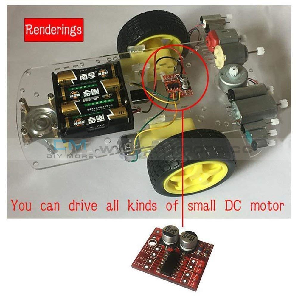
 Translation missing: en.products.product.regular_price $3.99{"id":4419937927239,"title":"Dual Mode PWM PULSE Square Wave Rectangular Wave Signal Adjustable Generator Control Module DC Stepper Motor Drive Driver Board","handle":"dual-mode-pwm-pulse-square-wave-rectangular-wave-signal-adjustable-generator-control-module-dc-stepper-motor-drive-driver-board","description":"\u003cdiv\u003e\n\u003cp\u003e\u003cwidget data-widget-type=\"customText\" id=\"33684419\" title=\"Head\" type=\"custom\"\u003e\u003c\/widget\u003e\u003c\/p\u003e\n\u003cp\u003e \u003c\/p\u003e\n\u003cp\u003e\u003cimg src=\"https:\/\/ae01.alicdn.com\/kf\/HTB12JMgilsmBKNjSZFsq6yXSVXaS.jpg\"\u003e\u003c\/p\u003e\n\u003cp\u003e \u003c\/p\u003e\n\u003cp style='box-sizing:content-box;font-size:13px;border-top:0px;font-family:\"Open Sans\", Arial, Helvetica, sans-serif, SimSun, 宋体;border-right:0px;vertical-align:baseline;white-space:normal;word-spacing:0px;border-bottom:0px;text-transform:none;font-weight:400;color:#000000;padding-bottom:0px;font-style:normal;padding-top:0px;padding-left:0px;margin:0px;border-left:0px;orphans:2;widows:2;letter-spacing:normal;padding-right:0px;background-color:#FFFFFF;text-indent:0px;font-variant-ligatures:normal;font-variant-caps:normal;font-variant-numeric:inherit;font-variant-east-asian:inherit;font-stretch:inherit;-webkit-text-stroke-width:0px;text-decoration-style:initial;text-decoration-color:initial;'\u003e\u003cspan style='box-sizing:content-box;font-size:18px;border-top:0px;font-family:\"Trebuchet MS\";border-right:0px;vertical-align:baseline;border-bottom:0px;padding-bottom:0px;padding-top:0px;padding-left:0px;margin:0px;border-left:0px;padding-right:0px;font-stretch:inherit;' data-spm-anchor-id=\"2114.10010108.1000023.i0.70637de6zbrpaz\"\u003e1.PWM signal generator, square wave rectangular wave signal generator\u003c\/span\u003e\u003c\/p\u003e\n\u003cp style='box-sizing:content-box;font-size:13px;border-top:0px;font-family:\"Open Sans\", Arial, Helvetica, sans-serif, SimSun, 宋体;border-right:0px;vertical-align:baseline;white-space:normal;word-spacing:0px;border-bottom:0px;text-transform:none;font-weight:400;color:#000000;padding-bottom:0px;font-style:normal;padding-top:0px;padding-left:0px;margin:0px;border-left:0px;orphans:2;widows:2;letter-spacing:normal;padding-right:0px;background-color:#FFFFFF;text-indent:0px;font-variant-ligatures:normal;font-variant-caps:normal;font-variant-numeric:inherit;font-variant-east-asian:inherit;font-stretch:inherit;-webkit-text-stroke-width:0px;text-decoration-style:initial;text-decoration-color:initial;'\u003e\u003cspan style='box-sizing:content-box;font-size:18px;border-top:0px;font-family:\"Trebuchet MS\";border-right:0px;vertical-align:baseline;border-bottom:0px;padding-bottom:0px;padding-top:0px;padding-left:0px;margin:0px;border-left:0px;padding-right:0px;font-stretch:inherit;'\u003e2. Used to generate square wave rectangular wave signals for controlling DC motor or stepper motor driver; used for servo motor, stepping motor, electric gripper, replacing PLC pulse, etc.\u003c\/span\u003e\u003c\/p\u003e\n\u003cp style='box-sizing:content-box;font-size:13px;border-top:0px;font-family:\"Open Sans\", Arial, Helvetica, sans-serif, SimSun, 宋体;border-right:0px;vertical-align:baseline;white-space:normal;word-spacing:0px;border-bottom:0px;text-transform:none;font-weight:400;color:#000000;padding-bottom:0px;font-style:normal;padding-top:0px;padding-left:0px;margin:0px;border-left:0px;orphans:2;widows:2;letter-spacing:normal;padding-right:0px;background-color:#FFFFFF;text-indent:0px;font-variant-ligatures:normal;font-variant-caps:normal;font-variant-numeric:inherit;font-variant-east-asian:inherit;font-stretch:inherit;-webkit-text-stroke-width:0px;text-decoration-style:initial;text-decoration-color:initial;'\u003e\u003cspan style='box-sizing:content-box;font-size:18px;border-top:0px;font-family:\"Trebuchet MS\";border-right:0px;vertical-align:baseline;border-bottom:0px;padding-bottom:0px;padding-top:0px;padding-left:0px;margin:0px;border-left:0px;padding-right:0px;font-stretch:inherit;'\u003e3. The supporting driver realizes dimming, speed regulation, control of solenoid valve, etc., but can not directly drive the load of the electric motor solenoid valve.\u003c\/span\u003e\u003c\/p\u003e\n\u003cp style='box-sizing:content-box;font-size:13px;border-top:0px;font-family:\"Open Sans\", Arial, Helvetica, sans-serif, SimSun, 宋体;border-right:0px;vertical-align:baseline;white-space:normal;word-spacing:0px;border-bottom:0px;text-transform:none;font-weight:400;color:#000000;padding-bottom:0px;font-style:normal;padding-top:0px;padding-left:0px;margin:0px;border-left:0px;orphans:2;widows:2;letter-spacing:normal;padding-right:0px;background-color:#FFFFFF;text-indent:0px;font-variant-ligatures:normal;font-variant-caps:normal;font-variant-numeric:inherit;font-variant-east-asian:inherit;font-stretch:inherit;-webkit-text-stroke-width:0px;text-decoration-style:initial;text-decoration-color:initial;'\u003e\u003cspan style='box-sizing:content-box;font-size:18px;border-top:0px;font-family:\"Trebuchet MS\";border-right:0px;vertical-align:baseline;border-bottom:0px;padding-bottom:0px;padding-top:0px;padding-left:0px;margin:0px;border-left:0px;padding-right:0px;font-stretch:inherit;'\u003e\u003c\/span\u003e \u003c\/p\u003e\n\u003cp style='box-sizing:content-box;font-size:13px;border-top:0px;font-family:\"Open Sans\", Arial, Helvetica, sans-serif, SimSun, 宋体;border-right:0px;vertical-align:baseline;white-space:normal;word-spacing:0px;border-bottom:0px;text-transform:none;font-weight:400;color:#000000;padding-bottom:0px;font-style:normal;padding-top:0px;padding-left:0px;margin:0px;border-left:0px;orphans:2;widows:2;letter-spacing:normal;padding-right:0px;background-color:#FFFFFF;text-indent:0px;font-variant-ligatures:normal;font-variant-caps:normal;font-variant-numeric:inherit;font-variant-east-asian:inherit;font-stretch:inherit;-webkit-text-stroke-width:0px;text-decoration-style:initial;text-decoration-color:initial;'\u003e\u003cspan style='box-sizing:content-box;font-size:18px;border-top:0px;font-family:\"Trebuchet MS\";border-right:0px;vertical-align:baseline;border-bottom:0px;color:#FF0000;padding-bottom:0px;padding-top:0px;padding-left:0px;margin:0px;border-left:0px;padding-right:0px;font-stretch:inherit;'\u003e1. Product Highlights:\u003c\/span\u003e\u003cbr style=\"box-sizing:content-box;\"\u003e\u003cspan style='box-sizing:content-box;font-size:18px;border-top:0px;font-family:\"Trebuchet MS\";border-right:0px;vertical-align:baseline;border-bottom:0px;padding-bottom:0px;padding-top:0px;padding-left:0px;margin:0px;border-left:0px;padding-right:0px;font-stretch:inherit;'\u003e1.1 Two modes can be selected:\u003c\/span\u003e\u003cbr style=\"box-sizing:content-box;\"\u003e\u003cspan style='box-sizing:content-box;font-size:18px;border-top:0px;font-family:\"Trebuchet MS\";border-right:0px;vertical-align:baseline;border-bottom:0px;padding-bottom:0px;padding-top:0px;padding-left:0px;margin:0px;border-left:0px;padding-right:0px;font-stretch:inherit;'\u003ePWM mode - frequency (continuous), duty cycle, pulse number adjustable;\u003c\/span\u003e\u003cbr style=\"box-sizing:content-box;\"\u003e\u003cspan style='box-sizing:content-box;font-size:18px;border-top:0px;font-family:\"Trebuchet MS\";border-right:0px;vertical-align:baseline;border-bottom:0px;padding-bottom:0px;padding-top:0px;padding-left:0px;margin:0px;border-left:0px;padding-right:0px;font-stretch:inherit;'\u003ePULSE pulse mode - positive pulse width time, negative pulse width time, delay start time, and number of pulses are adjustable.\u003c\/span\u003e\u003cbr style=\"box-sizing:content-box;\"\u003e\u003cspan style='box-sizing:content-box;font-size:18px;border-top:0px;font-family:\"Trebuchet MS\";border-right:0px;vertical-align:baseline;border-bottom:0px;padding-bottom:0px;padding-top:0px;padding-left:0px;margin:0px;border-left:0px;padding-right:0px;font-stretch:inherit;'\u003e1.2 With start and stop button, can control the output and stop of the signal\u003c\/span\u003e\u003cbr style=\"box-sizing:content-box;\"\u003e\u003cspan style='box-sizing:content-box;font-size:18px;border-top:0px;font-family:\"Trebuchet MS\";border-right:0px;vertical-align:baseline;border-bottom:0px;padding-bottom:0px;padding-top:0px;padding-left:0px;margin:0px;border-left:0px;padding-right:0px;font-stretch:inherit;'\u003e1.3 Wide voltage input 3.3-30V, with anti-reverse protection, 5.08mm terminal wiring\u003c\/span\u003e\u003c\/p\u003e\n\u003cp\u003e\u003cbr style='box-sizing:content-box;font-size:13px;font-family:\"Open Sans\", Arial, Helvetica, sans-serif, SimSun, 宋体;white-space:normal;word-spacing:0px;text-transform:none;font-weight:400;color:#000000;font-style:normal;orphans:2;widows:2;letter-spacing:normal;background-color:#FFFFFF;text-indent:0px;font-variant-ligatures:normal;font-variant-caps:normal;-webkit-text-stroke-width:0px;text-decoration-style:initial;text-decoration-color:initial;'\u003e\u003cspan style='box-sizing:content-box;font-size:18px;border-top:0px;font-family:\"Trebuchet MS\";border-right:0px;vertical-align:baseline;white-space:normal;word-spacing:0px;border-bottom:0px;text-transform:none;font-weight:400;color:#FF0000;padding-bottom:0px;font-style:normal;padding-top:0px;padding-left:0px;margin:0px;border-left:0px;orphans:2;widows:2;letter-spacing:normal;padding-right:0px;background-color:#FFFFFF;text-indent:0px;font-variant-ligatures:normal;font-variant-caps:normal;font-variant-numeric:inherit;font-variant-east-asian:inherit;font-stretch:inherit;-webkit-text-stroke-width:0px;text-decoration-style:initial;text-decoration-color:initial;'\u003e2. Technical parameters:\u003c\/span\u003e\u003cbr style='box-sizing:content-box;font-size:13px;font-family:\"Open Sans\", Arial, Helvetica, sans-serif, SimSun, 宋体;white-space:normal;word-spacing:0px;text-transform:none;font-weight:400;color:#000000;font-style:normal;orphans:2;widows:2;letter-spacing:normal;background-color:#FFFFFF;text-indent:0px;font-variant-ligatures:normal;font-variant-caps:normal;-webkit-text-stroke-width:0px;text-decoration-style:initial;text-decoration-color:initial;'\u003e\u003cspan style='box-sizing:content-box;font-size:18px;border-top:0px;font-family:\"Trebuchet MS\";border-right:0px;vertical-align:baseline;white-space:normal;word-spacing:0px;border-bottom:0px;text-transform:none;font-weight:400;color:#000000;padding-bottom:0px;font-style:normal;padding-top:0px;padding-left:0px;margin:0px;border-left:0px;orphans:2;widows:2;letter-spacing:normal;padding-right:0px;background-color:#FFFFFF;text-indent:0px;font-variant-ligatures:normal;font-variant-caps:normal;font-variant-numeric:inherit;font-variant-east-asian:inherit;font-stretch:inherit;-webkit-text-stroke-width:0px;text-decoration-style:initial;text-decoration-color:initial;'\u003e2.1 Working voltage: 3.3~30V, with anti-reverse protection\u003c\/span\u003e\u003cbr style='box-sizing:content-box;font-size:13px;font-family:\"Open Sans\", Arial, Helvetica, sans-serif, SimSun, 宋体;white-space:normal;word-spacing:0px;text-transform:none;font-weight:400;color:#000000;font-style:normal;orphans:2;widows:2;letter-spacing:normal;background-color:#FFFFFF;text-indent:0px;font-variant-ligatures:normal;font-variant-caps:normal;-webkit-text-stroke-width:0px;text-decoration-style:initial;text-decoration-color:initial;'\u003e\u003cspan style='box-sizing:content-box;font-size:18px;border-top:0px;font-family:\"Trebuchet MS\";border-right:0px;vertical-align:baseline;white-space:normal;word-spacing:0px;border-bottom:0px;text-transform:none;font-weight:400;color:#000000;padding-bottom:0px;font-style:normal;padding-top:0px;padding-left:0px;margin:0px;border-left:0px;orphans:2;widows:2;letter-spacing:normal;padding-right:0px;background-color:#FFFFFF;text-indent:0px;font-variant-ligatures:normal;font-variant-caps:normal;font-variant-numeric:inherit;font-variant-east-asian:inherit;font-stretch:inherit;-webkit-text-stroke-width:0px;text-decoration-style:initial;text-decoration-color:initial;'\u003e2.2 Frequency range: 1Hz~150KHz, accuracy about 2%\u003c\/span\u003e\u003cbr style='box-sizing:content-box;font-size:13px;font-family:\"Open Sans\", Arial, Helvetica, sans-serif, SimSun, 宋体;white-space:normal;word-spacing:0px;text-transform:none;font-weight:400;color:#000000;font-style:normal;orphans:2;widows:2;letter-spacing:normal;background-color:#FFFFFF;text-indent:0px;font-variant-ligatures:normal;font-variant-caps:normal;-webkit-text-stroke-width:0px;text-decoration-style:initial;text-decoration-color:initial;'\u003e\u003cspan style='box-sizing:content-box;font-size:18px;border-top:0px;font-family:\"Trebuchet MS\";border-right:0px;vertical-align:baseline;white-space:normal;word-spacing:0px;border-bottom:0px;text-transform:none;font-weight:400;color:#000000;padding-bottom:0px;font-style:normal;padding-top:0px;padding-left:0px;margin:0px;border-left:0px;orphans:2;widows:2;letter-spacing:normal;padding-right:0px;background-color:#FFFFFF;text-indent:0px;font-variant-ligatures:normal;font-variant-caps:normal;font-variant-numeric:inherit;font-variant-east-asian:inherit;font-stretch:inherit;-webkit-text-stroke-width:0px;text-decoration-style:initial;text-decoration-color:initial;'\u003e2.3 duty cycle range: 0-100%, 1% stepping\u003c\/span\u003e\u003cbr style='box-sizing:content-box;font-size:13px;font-family:\"Open Sans\", Arial, Helvetica, sans-serif, SimSun, 宋体;white-space:normal;word-spacing:0px;text-transform:none;font-weight:400;color:#000000;font-style:normal;orphans:2;widows:2;letter-spacing:normal;background-color:#FFFFFF;text-indent:0px;font-variant-ligatures:normal;font-variant-caps:normal;-webkit-text-stroke-width:0px;text-decoration-style:initial;text-decoration-color:initial;'\u003e\u003cspan style='box-sizing:content-box;font-size:18px;border-top:0px;font-family:\"Trebuchet MS\";border-right:0px;vertical-align:baseline;white-space:normal;word-spacing:0px;border-bottom:0px;text-transform:none;font-weight:400;color:#000000;padding-bottom:0px;font-style:normal;padding-top:0px;padding-left:0px;margin:0px;border-left:0px;orphans:2;widows:2;letter-spacing:normal;padding-right:0px;background-color:#FFFFFF;text-indent:0px;font-variant-ligatures:normal;font-variant-caps:normal;font-variant-numeric:inherit;font-variant-east-asian:inherit;font-stretch:inherit;-webkit-text-stroke-width:0px;text-decoration-style:initial;text-decoration-color:initial;'\u003e2.4 number of pulses: 1-9999, or infinite (display ‘----' stands for infinity)\u003c\/span\u003e\u003cbr style='box-sizing:content-box;font-size:13px;font-family:\"Open Sans\", Arial, Helvetica, sans-serif, SimSun, 宋体;white-space:normal;word-spacing:0px;text-transform:none;font-weight:400;color:#000000;font-style:normal;orphans:2;widows:2;letter-spacing:normal;background-color:#FFFFFF;text-indent:0px;font-variant-ligatures:normal;font-variant-caps:normal;-webkit-text-stroke-width:0px;text-decoration-style:initial;text-decoration-color:initial;'\u003e\u003cspan style='box-sizing:content-box;font-size:18px;border-top:0px;font-family:\"Trebuchet MS\";border-right:0px;vertical-align:baseline;white-space:normal;word-spacing:0px;border-bottom:0px;text-transform:none;font-weight:400;color:#000000;padding-bottom:0px;font-style:normal;padding-top:0px;padding-left:0px;margin:0px;border-left:0px;orphans:2;widows:2;letter-spacing:normal;padding-right:0px;background-color:#FFFFFF;text-indent:0px;font-variant-ligatures:normal;font-variant-caps:normal;font-variant-numeric:inherit;font-variant-east-asian:inherit;font-stretch:inherit;-webkit-text-stroke-width:0px;text-decoration-style:initial;text-decoration-color:initial;'\u003e2.5 delay output time: 0.000s-9999s, the minimum can be set 1ms\u003c\/span\u003e\u003cbr style='box-sizing:content-box;font-size:13px;font-family:\"Open Sans\", Arial, Helvetica, sans-serif, SimSun, 宋体;white-space:normal;word-spacing:0px;text-transform:none;font-weight:400;color:#000000;font-style:normal;orphans:2;widows:2;letter-spacing:normal;background-color:#FFFFFF;text-indent:0px;font-variant-ligatures:normal;font-variant-caps:normal;-webkit-text-stroke-width:0px;text-decoration-style:initial;text-decoration-color:initial;'\u003e\u003cspan style='box-sizing:content-box;font-size:18px;border-top:0px;font-family:\"Trebuchet MS\";border-right:0px;vertical-align:baseline;white-space:normal;word-spacing:0px;border-bottom:0px;text-transform:none;font-weight:400;color:#000000;padding-bottom:0px;font-style:normal;padding-top:0px;padding-left:0px;margin:0px;border-left:0px;orphans:2;widows:2;letter-spacing:normal;padding-right:0px;background-color:#FFFFFF;text-indent:0px;font-variant-ligatures:normal;font-variant-caps:normal;font-variant-numeric:inherit;font-variant-east-asian:inherit;font-stretch:inherit;-webkit-text-stroke-width:0px;text-decoration-style:initial;text-decoration-color:initial;'\u003e2.6 positive and negative pulse width length: 0.000s-9999s, the minimum can be set 1ms\u003c\/span\u003e\u003cbr style='box-sizing:content-box;font-size:13px;font-family:\"Open Sans\", Arial, Helvetica, sans-serif, SimSun, 宋体;white-space:normal;word-spacing:0px;text-transform:none;font-weight:400;color:#000000;font-style:normal;orphans:2;widows:2;letter-spacing:normal;background-color:#FFFFFF;text-indent:0px;font-variant-ligatures:normal;font-variant-caps:normal;-webkit-text-stroke-width:0px;text-decoration-style:initial;text-decoration-color:initial;'\u003e\u003cspan style='box-sizing:content-box;font-size:18px;border-top:0px;font-family:\"Trebuchet MS\";border-right:0px;vertical-align:baseline;white-space:normal;word-spacing:0px;border-bottom:0px;text-transform:none;font-weight:400;color:#000000;padding-bottom:0px;font-style:normal;padding-top:0px;padding-left:0px;margin:0px;border-left:0px;orphans:2;widows:2;letter-spacing:normal;padding-right:0px;background-color:#FFFFFF;text-indent:0px;font-variant-ligatures:normal;font-variant-caps:normal;font-variant-numeric:inherit;font-variant-east-asian:inherit;font-stretch:inherit;-webkit-text-stroke-width:0px;text-decoration-style:initial;text-decoration-color:initial;'\u003e2.7 signal loading capacity: less than 30mA\u003c\/span\u003e\u003cbr style='box-sizing:content-box;font-size:13px;font-family:\"Open Sans\", Arial, Helvetica, sans-serif, SimSun, 宋体;white-space:normal;word-spacing:0px;text-transform:none;font-weight:400;color:#000000;font-style:normal;orphans:2;widows:2;letter-spacing:normal;background-color:#FFFFFF;text-indent:0px;font-variant-ligatures:normal;font-variant-caps:normal;-webkit-text-stroke-width:0px;text-decoration-style:initial;text-decoration-color:initial;'\u003e\u003cspan style='box-sizing:content-box;font-size:18px;border-top:0px;font-family:\"Trebuchet MS\";border-right:0px;vertical-align:baseline;white-space:normal;word-spacing:0px;border-bottom:0px;text-transform:none;font-weight:400;color:#000000;padding-bottom:0px;font-style:normal;padding-top:0px;padding-left:0px;margin:0px;border-left:0px;orphans:2;widows:2;letter-spacing:normal;padding-right:0px;background-color:#FFFFFF;text-indent:0px;font-variant-ligatures:normal;font-variant-caps:normal;font-variant-numeric:inherit;font-variant-east-asian:inherit;font-stretch:inherit;-webkit-text-stroke-width:0px;text-decoration-style:initial;text-decoration-color:initial;'\u003e2.8 Output signal amplitude: amplitude is equal to the supply voltage\u003c\/span\u003e\u003cbr style='box-sizing:content-box;font-size:13px;font-family:\"Open Sans\", Arial, Helvetica, sans-serif, SimSun, 宋体;white-space:normal;word-spacing:0px;text-transform:none;font-weight:400;color:#000000;font-style:normal;orphans:2;widows:2;letter-spacing:normal;background-color:#FFFFFF;text-indent:0px;font-variant-ligatures:normal;font-variant-caps:normal;-webkit-text-stroke-width:0px;text-decoration-style:initial;text-decoration-color:initial;'\u003e\u003cspan style='box-sizing:content-box;font-size:18px;border-top:0px;font-family:\"Trebuchet MS\";border-right:0px;vertical-align:baseline;white-space:normal;word-spacing:0px;border-bottom:0px;text-transform:none;font-weight:400;color:#000000;padding-bottom:0px;font-style:normal;padding-top:0px;padding-left:0px;margin:0px;border-left:0px;orphans:2;widows:2;letter-spacing:normal;padding-right:0px;background-color:#FFFFFF;text-indent:0px;font-variant-ligatures:normal;font-variant-caps:normal;font-variant-numeric:inherit;font-variant-east-asian:inherit;font-stretch:inherit;-webkit-text-stroke-width:0px;text-decoration-style:initial;text-decoration-color:initial;'\u003e2.9 Product size: 60mm*32mm*10mm\u003c\/span\u003e\u003cbr style='box-sizing:content-box;font-size:13px;font-family:\"Open Sans\", Arial, Helvetica, sans-serif, SimSun, 宋体;white-space:normal;word-spacing:0px;text-transform:none;font-weight:400;color:#000000;font-style:normal;orphans:2;widows:2;letter-spacing:normal;background-color:#FFFFFF;text-indent:0px;font-variant-ligatures:normal;font-variant-caps:normal;-webkit-text-stroke-width:0px;text-decoration-style:initial;text-decoration-color:initial;'\u003e\u003cspan style='box-sizing:content-box;font-size:18px;border-top:0px;font-family:\"Trebuchet MS\";border-right:0px;vertical-align:baseline;white-space:normal;word-spacing:0px;border-bottom:0px;text-transform:none;font-weight:400;color:#000000;padding-bottom:0px;font-style:normal;padding-top:0px;padding-left:0px;margin:0px;border-left:0px;orphans:2;widows:2;letter-spacing:normal;padding-right:0px;background-color:#FFFFFF;text-indent:0px;font-variant-ligatures:normal;font-variant-caps:normal;font-variant-numeric:inherit;font-variant-east-asian:inherit;font-stretch:inherit;-webkit-text-stroke-width:0px;text-decoration-style:initial;text-decoration-color:initial;'\u003e2.10 Product Weight: 18g\u003c\/span\u003e\u003cbr style='box-sizing:content-box;font-size:13px;font-family:\"Open Sans\", Arial, Helvetica, sans-serif, SimSun, 宋体;white-space:normal;word-spacing:0px;text-transform:none;font-weight:400;color:#000000;font-style:normal;orphans:2;widows:2;letter-spacing:normal;background-color:#FFFFFF;text-indent:0px;font-variant-ligatures:normal;font-variant-caps:normal;-webkit-text-stroke-width:0px;text-decoration-style:initial;text-decoration-color:initial;'\u003e\u003cspan style='box-sizing:content-box;font-size:18px;border-top:0px;font-family:\"Trebuchet MS\";border-right:0px;vertical-align:baseline;white-space:normal;word-spacing:0px;border-bottom:0px;text-transform:none;font-weight:400;color:#000000;padding-bottom:0px;font-style:normal;padding-top:0px;padding-left:0px;margin:0px;border-left:0px;orphans:2;widows:2;letter-spacing:normal;padding-right:0px;background-color:#FFFFFF;text-indent:0px;font-variant-ligatures:normal;font-variant-caps:normal;font-variant-numeric:inherit;font-variant-east-asian:inherit;font-stretch:inherit;-webkit-text-stroke-width:0px;text-decoration-style:initial;text-decoration-color:initial;'\u003e2.11 Packing: Anti-static bag\u003c\/span\u003e\u003cspan style='font-size:13px;font-family:\"Open Sans\", Arial, Helvetica, sans-serif, SimSun, 宋体;white-space:normal;word-spacing:0px;text-transform:none;float:none;font-weight:400;color:#000000;font-style:normal;orphans:2;widows:2;display:inline !important;letter-spacing:normal;background-color:#FFFFFF;text-indent:0px;font-variant-ligatures:normal;font-variant-caps:normal;-webkit-text-stroke-width:0px;text-decoration-style:initial;text-decoration-color:initial;'\u003e\u003c\/span\u003e\u003c\/p\u003e\n\u003cp style='box-sizing:content-box;font-size:13px;border-top:0px;font-family:\"Open Sans\", Arial, Helvetica, sans-serif, SimSun, 宋体;border-right:0px;vertical-align:baseline;white-space:normal;word-spacing:0px;border-bottom:0px;text-transform:none;font-weight:400;color:#000000;padding-bottom:0px;font-style:normal;padding-top:0px;padding-left:0px;margin:0px;border-left:0px;orphans:2;widows:2;letter-spacing:normal;padding-right:0px;background-color:#FFFFFF;text-indent:0px;font-variant-ligatures:normal;font-variant-caps:normal;font-variant-numeric:inherit;font-variant-east-asian:inherit;font-stretch:inherit;-webkit-text-stroke-width:0px;text-decoration-style:initial;text-decoration-color:initial;'\u003e\u003cspan style='box-sizing:content-box;font-size:18px;border-top:0px;font-family:\"Trebuchet MS\";border-right:0px;vertical-align:baseline;border-bottom:0px;padding-bottom:0px;padding-top:0px;padding-left:0px;margin:0px;border-left:0px;padding-right:0px;font-stretch:inherit;'\u003e\u003c\/span\u003e \u003c\/p\u003e\n\u003cp style='box-sizing:content-box;font-size:13px;border-top:0px;font-family:\"Open Sans\", Arial, Helvetica, sans-serif, SimSun, 宋体;border-right:0px;vertical-align:baseline;white-space:normal;word-spacing:0px;border-bottom:0px;text-transform:none;font-weight:400;color:#000000;padding-bottom:0px;font-style:normal;padding-top:0px;padding-left:0px;margin:0px;border-left:0px;orphans:2;widows:2;letter-spacing:normal;padding-right:0px;background-color:#FFFFFF;text-indent:0px;font-variant-ligatures:normal;font-variant-caps:normal;font-variant-numeric:inherit;font-variant-east-asian:inherit;font-stretch:inherit;-webkit-text-stroke-width:0px;text-decoration-style:initial;text-decoration-color:initial;'\u003e\u003cspan style='box-sizing:content-box;font-size:18px;border-top:0px;font-family:\"Trebuchet MS\";border-right:0px;vertical-align:baseline;border-bottom:0px;color:#FF0000;padding-bottom:0px;padding-top:0px;padding-left:0px;margin:0px;border-left:0px;padding-right:0px;font-stretch:inherit;'\u003e3. PWM mode (display has \"%\" for PWM mode)\u003c\/span\u003e\u003c\/p\u003e\n\u003cp style='box-sizing:content-box;font-size:13px;border-top:0px;font-family:\"Open Sans\", Arial, Helvetica, sans-serif, SimSun, 宋体;border-right:0px;vertical-align:baseline;white-space:normal;word-spacing:0px;border-bottom:0px;text-transform:none;font-weight:400;color:#000000;padding-bottom:0px;font-style:normal;padding-top:0px;padding-left:0px;margin:0px;border-left:0px;orphans:2;widows:2;letter-spacing:normal;padding-right:0px;background-color:#FFFFFF;text-indent:0px;font-variant-ligatures:normal;font-variant-caps:normal;font-variant-numeric:inherit;font-variant-east-asian:inherit;font-stretch:inherit;-webkit-text-stroke-width:0px;text-decoration-style:initial;text-decoration-color:initial;'\u003e\u003cspan style='box-sizing:content-box;font-size:18px;border-top:0px;font-family:\"Trebuchet MS\";border-right:0px;vertical-align:baseline;border-bottom:0px;padding-bottom:0px;padding-top:0px;padding-left:0px;margin:0px;border-left:0px;padding-right:0px;font-stretch:inherit;'\u003eThe factory default mode is PWM mode, FREQ+ and FREQ-key set frequency, DUTY+ and DUTY-button set duty cycle; short press STOP button control signal output or stop, stop output is 0, the screen displays “OUT” mark as There is output, otherwise it stops output; the default factory frequency is 1KHZ and the duty cycle is 50%.\u003c\/span\u003e\u003c\/p\u003e\n\u003cp style='box-sizing:content-box;font-size:13px;border-top:0px;font-family:\"Open Sans\", Arial, Helvetica, sans-serif, SimSun, 宋体;border-right:0px;vertical-align:baseline;white-space:normal;word-spacing:0px;border-bottom:0px;text-transform:none;font-weight:400;color:#000000;padding-bottom:0px;font-style:normal;padding-top:0px;padding-left:0px;margin:0px;border-left:0px;orphans:2;widows:2;letter-spacing:normal;padding-right:0px;background-color:#FFFFFF;text-indent:0px;font-variant-ligatures:normal;font-variant-caps:normal;font-variant-numeric:inherit;font-variant-east-asian:inherit;font-stretch:inherit;-webkit-text-stroke-width:0px;text-decoration-style:initial;text-decoration-color:initial;'\u003e\u003cspan style='box-sizing:content-box;font-size:18px;border-top:0px;font-family:\"Trebuchet MS\";border-right:0px;vertical-align:baseline;border-bottom:0px;padding-bottom:0px;padding-top:0px;padding-left:0px;margin:0px;border-left:0px;padding-right:0px;font-stretch:inherit;'\u003eIf you want to switch to PULSE pulse mode, long press the SET button (more than 6 seconds), do not release, you will see the screen change, \"%\" disappears, it is PULSE mode.\u003c\/span\u003e\u003c\/p\u003e\n\u003cp style='box-sizing:content-box;font-size:13px;border-top:0px;font-family:\"Open Sans\", Arial, Helvetica, sans-serif, SimSun, 宋体;border-right:0px;vertical-align:baseline;white-space:normal;word-spacing:0px;border-bottom:0px;text-transform:none;font-weight:400;color:#000000;padding-bottom:0px;font-style:normal;padding-top:0px;padding-left:0px;margin:0px;border-left:0px;orphans:2;widows:2;letter-spacing:normal;padding-right:0px;background-color:#FFFFFF;text-indent:0px;font-variant-ligatures:normal;font-variant-caps:normal;font-variant-numeric:inherit;font-variant-east-asian:inherit;font-stretch:inherit;-webkit-text-stroke-width:0px;text-decoration-style:initial;text-decoration-color:initial;'\u003e\u003cspan style='box-sizing:content-box;font-size:18px;border-top:0px;font-family:\"Trebuchet MS\";border-right:0px;vertical-align:baseline;border-bottom:0px;padding-bottom:0px;padding-top:0px;padding-left:0px;margin:0px;border-left:0px;padding-right:0px;font-stretch:inherit;'\u003e3.2 PULSE pulse mode (No \"%\" on the right side of the display is displayed in PULSE mode)\u003c\/span\u003e\u003c\/p\u003e\n\u003cp style='box-sizing:content-box;font-size:13px;border-top:0px;font-family:\"Open Sans\", Arial, Helvetica, sans-serif, SimSun, 宋体;border-right:0px;vertical-align:baseline;white-space:normal;word-spacing:0px;border-bottom:0px;text-transform:none;font-weight:400;color:#000000;padding-bottom:0px;font-style:normal;padding-top:0px;padding-left:0px;margin:0px;border-left:0px;orphans:2;widows:2;letter-spacing:normal;padding-right:0px;background-color:#FFFFFF;text-indent:0px;font-variant-ligatures:normal;font-variant-caps:normal;font-variant-numeric:inherit;font-variant-east-asian:inherit;font-stretch:inherit;-webkit-text-stroke-width:0px;text-decoration-style:initial;text-decoration-color:initial;'\u003e\u003cspan style='box-sizing:content-box;font-size:18px;border-top:0px;font-family:\"Trebuchet MS\";border-right:0px;vertical-align:baseline;border-bottom:0px;padding-bottom:0px;padding-top:0px;padding-left:0px;margin:0px;border-left:0px;padding-right:0px;font-stretch:inherit;'\u003eThe P+ and P- buttons set the positive pulse width time, the LCD screen shows up, the N+ and N- buttons set the negative pulse width time, the LCD screen displays downwards, the unit is seconds; short press the STOP button to control the signal output or stop, stop output It is 0, the screen displays “OUT” mark as output, otherwise it stops output; the default factory positive pulse width is 0.5 second, and the negative pulse width is 0.5 second.\u003c\/span\u003e\u003c\/p\u003e\n\u003cp style='box-sizing:content-box;font-size:13px;border-top:0px;font-family:\"Open Sans\", Arial, Helvetica, sans-serif, SimSun, 宋体;border-right:0px;vertical-align:baseline;white-space:normal;word-spacing:0px;border-bottom:0px;text-transform:none;font-weight:400;color:#000000;padding-bottom:0px;font-style:normal;padding-top:0px;padding-left:0px;margin:0px;border-left:0px;orphans:2;widows:2;letter-spacing:normal;padding-right:0px;background-color:#FFFFFF;text-indent:0px;font-variant-ligatures:normal;font-variant-caps:normal;font-variant-numeric:inherit;font-variant-east-asian:inherit;font-stretch:inherit;-webkit-text-stroke-width:0px;text-decoration-style:initial;text-decoration-color:initial;'\u003e\u003cspan style='box-sizing:content-box;font-size:18px;border-top:0px;font-family:\"Trebuchet MS\";border-right:0px;vertical-align:baseline;border-bottom:0px;padding-bottom:0px;padding-top:0px;padding-left:0px;margin:0px;border-left:0px;padding-right:0px;font-stretch:inherit;'\u003ePulse number and delay time setting - In PULSE mode, press and hold the SET button for 2 seconds and then release, enter the pulse number and delay time setting interface, the screen displays SET, it will be turned off and cleared after entering. Output pulse; P+ and P- buttons set delay time, N+ and N- buttons set pulse number, factory default delay time is 0 seconds, pulse number is infinite (display ----); Press the button for 2 seconds, automatically return to the pulse interface, press the STOP button, after the delay setting time, start to send the set number of pulses, if the number of pulses is sent, it will automatically output 0, if the period is not sent, press the STOP button. The output pulse will be turned off and cleared, and the number of pulses set will be issued each time it is started.\u003c\/span\u003e\u003c\/p\u003e\n\u003cp style='box-sizing:content-box;font-size:13px;border-top:0px;font-family:\"Open Sans\", Arial, Helvetica, sans-serif, SimSun, 宋体;border-right:0px;vertical-align:baseline;white-space:normal;word-spacing:0px;border-bottom:0px;text-transform:none;font-weight:400;color:#000000;padding-bottom:0px;font-style:normal;padding-top:0px;padding-left:0px;margin:0px;border-left:0px;orphans:2;widows:2;letter-spacing:normal;padding-right:0px;background-color:#FFFFFF;text-indent:0px;font-variant-ligatures:normal;font-variant-caps:normal;font-variant-numeric:inherit;font-variant-east-asian:inherit;font-stretch:inherit;-webkit-text-stroke-width:0px;text-decoration-style:initial;text-decoration-color:initial;'\u003e\u003cspan style='box-sizing:content-box;font-size:18px;border-top:0px;font-family:\"Trebuchet MS\";border-right:0px;vertical-align:baseline;border-bottom:0px;padding-bottom:0px;padding-top:0px;padding-left:0px;margin:0px;border-left:0px;padding-right:0px;font-stretch:inherit;'\u003e3.3 Application Operation Examples\u003c\/span\u003e\u003cbr style=\"box-sizing:content-box;\"\u003e\u003cspan style='box-sizing:content-box;font-size:18px;border-top:0px;font-family:\"Trebuchet MS\";border-right:0px;vertical-align:baseline;border-bottom:0px;padding-bottom:0px;padding-top:0px;padding-left:0px;margin:0px;border-left:0px;padding-right:0px;font-stretch:inherit;'\u003e3.3.1 PWM output 20KHZ, 60% duty cycle: Select PWM mode, the frequency is set to 20.00, and the duty ratio is set to 060%.\u003c\/span\u003e\u003cbr style=\"box-sizing:content-box;\"\u003e\u003cspan style='box-sizing:content-box;font-size:18px;border-top:0px;font-family:\"Trebuchet MS\";border-right:0px;vertical-align:baseline;border-bottom:0px;padding-bottom:0px;padding-top:0px;padding-left:0px;margin:0px;border-left:0px;padding-right:0px;font-stretch:inherit;'\u003e3.3.2 The output is turned on for 0.6 seconds and turned off for 0.2 seconds. Infinite loop: select PULSE mode, the positive pulse width is set to 0.600, the negative pulse width is set to 0.200, the delay time is set to 0.000, and the number of pulses is set to --- -.\u003c\/span\u003e\u003cbr style=\"box-sizing:content-box;\"\u003e\u003cspan style='box-sizing:content-box;font-size:18px;border-top:0px;font-family:\"Trebuchet MS\";border-right:0px;vertical-align:baseline;border-bottom:0px;padding-bottom:0px;padding-top:0px;padding-left:0px;margin:0px;border-left:0px;padding-right:0px;font-stretch:inherit;'\u003e3.3.3 Power on or press the start button, delay 5 seconds, then the output is turned on for 0.6 seconds, off 0.2 seconds, infinite loop: select PULSE mode, positive pulse width is set to 0.600, negative pulse width is set to 0.200, delay The time is set to 5.000 and the number of pulses is set to ----.\u003c\/span\u003e\u003cbr style=\"box-sizing:content-box;\"\u003e\u003cspan style='box-sizing:content-box;font-size:18px;border-top:0px;font-family:\"Trebuchet MS\";border-right:0px;vertical-align:baseline;border-bottom:0px;padding-bottom:0px;padding-top:0px;padding-left:0px;margin:0px;border-left:0px;padding-right:0px;font-stretch:inherit;'\u003e3.3.4 Power on or press the start button, delay 5 seconds, then output high level 10ms low level 10ms pulse 100: select PULSE mode, positive pulse width is set to 0.010, negative pulse width is set to 0.010, delay The time is set to 5.000 and the number of pulses is set to 0100.\u003c\/span\u003e\u003cbr style=\"box-sizing:content-box;\"\u003e\u003cspan style='box-sizing:content-box;font-size:18px;border-top:0px;font-family:\"Trebuchet MS\";border-right:0px;vertical-align:baseline;border-bottom:0px;padding-bottom:0px;padding-top:0px;padding-left:0px;margin:0px;border-left:0px;padding-right:0px;font-stretch:inherit;'\u003e3.3.5 Power-on delay for 10 seconds, then permanently output signal: select PULSE mode, the positive pulse width is set to a number greater than 0, the negative pulse width is set to 0, the delay time is set to 10.00 seconds, and the pulse number is infinite. (----).\u003c\/span\u003e\u003cbr style=\"box-sizing:content-box;\"\u003e\u003cspan style='box-sizing:content-box;font-size:18px;border-top:0px;font-family:\"Trebuchet MS\";border-right:0px;vertical-align:baseline;border-bottom:0px;padding-bottom:0px;padding-top:0px;padding-left:0px;margin:0px;border-left:0px;padding-right:0px;font-stretch:inherit;'\u003e3.3.6 Other applications can explore or consult customer service\u003c\/span\u003e\u003c\/p\u003e\n\u003cp style='box-sizing:content-box;font-size:13px;border-top:0px;font-family:\"Open Sans\", Arial, Helvetica, sans-serif, SimSun, 宋体;border-right:0px;vertical-align:baseline;white-space:normal;word-spacing:0px;border-bottom:0px;text-transform:none;font-weight:400;color:#000000;padding-bottom:0px;font-style:normal;padding-top:0px;padding-left:0px;margin:0px;border-left:0px;orphans:2;widows:2;letter-spacing:normal;padding-right:0px;background-color:#FFFFFF;text-indent:0px;font-variant-ligatures:normal;font-variant-caps:normal;font-variant-numeric:inherit;font-variant-east-asian:inherit;font-stretch:inherit;-webkit-text-stroke-width:0px;text-decoration-style:initial;text-decoration-color:initial;'\u003e\u003cspan style='box-sizing:content-box;font-size:18px;border-top:0px;font-family:\"Trebuchet MS\";border-right:0px;vertical-align:baseline;border-bottom:0px;padding-bottom:0px;padding-top:0px;padding-left:0px;margin:0px;border-left:0px;padding-right:0px;font-stretch:inherit;'\u003eAll setup parameters are not lost when they are turned off.\u003c\/span\u003e\u003c\/p\u003e\n\u003cp style='box-sizing:content-box;font-size:13px;border-top:0px;font-family:\"Open Sans\", Arial, Helvetica, sans-serif, SimSun, 宋体;border-right:0px;vertical-align:baseline;white-space:normal;word-spacing:0px;border-bottom:0px;text-transform:none;font-weight:400;color:#000000;padding-bottom:0px;font-style:normal;padding-top:0px;padding-left:0px;margin:0px;border-left:0px;orphans:2;widows:2;letter-spacing:normal;padding-right:0px;background-color:#FFFFFF;text-indent:0px;font-variant-ligatures:normal;font-variant-caps:normal;font-variant-numeric:inherit;font-variant-east-asian:inherit;font-stretch:inherit;-webkit-text-stroke-width:0px;text-decoration-style:initial;text-decoration-color:initial;'\u003e\u003cspan style='box-sizing:content-box;font-size:18px;border-top:0px;font-family:\"Trebuchet MS\";border-right:0px;vertical-align:baseline;border-bottom:0px;padding-bottom:0px;padding-top:0px;padding-left:0px;margin:0px;border-left:0px;padding-right:0px;font-stretch:inherit;'\u003e\u003c\/span\u003e \u003c\/p\u003e\n\u003cp style='box-sizing:content-box;font-size:13px;border-top:0px;font-family:\"Open Sans\", Arial, Helvetica, sans-serif, SimSun, 宋体;border-right:0px;vertical-align:baseline;white-space:normal;word-spacing:0px;border-bottom:0px;text-transform:none;font-weight:400;color:#000000;padding-bottom:0px;font-style:normal;padding-top:0px;padding-left:0px;margin:0px;border-left:0px;orphans:2;widows:2;letter-spacing:normal;padding-right:0px;background-color:#FFFFFF;text-indent:0px;font-variant-ligatures:normal;font-variant-caps:normal;font-variant-numeric:inherit;font-variant-east-asian:inherit;font-stretch:inherit;-webkit-text-stroke-width:0px;text-decoration-style:initial;text-decoration-color:initial;'\u003e\u003cspan style='box-sizing:content-box;font-size:18px;border-top:0px;font-family:\"Trebuchet MS\";border-right:0px;vertical-align:baseline;border-bottom:0px;padding-bottom:0px;padding-top:0px;padding-left:0px;margin:0px;border-left:0px;padding-right:0px;font-stretch:inherit;'\u003e\u003c\/span\u003e \u003c\/p\u003e\n\u003cspan style='box-sizing:content-box;font-size:18px;border-top:0px;font-family:\"Trebuchet MS\";border-right:0px;vertical-align:baseline;border-bottom:0px;padding-bottom:0px;padding-top:0px;padding-left:0px;margin:0px;border-left:0px;padding-right:0px;font-stretch:inherit;'\u003e \u003cp\u003e\u003cimg src=\"https:\/\/ae01.alicdn.com\/kf\/HTB1VXjubuUXBuNjt_a0q6AysXXaA.jpg\"\u003e\u003c\/p\u003e\n\u003cp\u003e \u003c\/p\u003e\n\u003cp\u003e\u003cimg style=\"width:1000px;\" src=\"https:\/\/ae01.alicdn.com\/kf\/HTB1_riVa2WG3KVjSZFPq6xaiXXak.jpg\"\u003e\u003c\/p\u003e\n\u003cp\u003e\u003cimg style=\"width:1000px;\" src=\"https:\/\/ae01.alicdn.com\/kf\/HTB1MxCVa.GF3KVjSZFoq6zmpFXas.jpg\"\u003e\u003c\/p\u003e\n\u003cp\u003e\u003cimg style=\"width:1000px;\" src=\"https:\/\/ae01.alicdn.com\/kf\/HTB17Z15aWSs3KVjSZPiq6AsiVXaQ.jpg\"\u003e\u003c\/p\u003e\n\u003cp\u003e\u003cimg src=\"https:\/\/ae01.alicdn.com\/kf\/HTB1Hc.uimcqBKNjSZFgq6x_kXXaq.jpg\"\u003e\u003c\/p\u003e\n\u003cp\u003e \u003c\/p\u003e\n\u003cwidget data-widget-type=\"customText\" id=\"24006699\" title=\"Related\" type=\"custom\"\u003e\u003c\/widget\u003e\r \u003cp\u003e\u003c\/p\u003e\u003c\/span\u003e \u003cp\u003e \u003cscript\u003ewindow.adminAccountId=227552571;\u003c\/script\u003e \u003c\/p\u003e\n\u003c\/div\u003e","published_at":"2019-12-27T16:27:56+08:00","created_at":"2019-12-27T16:28:04+08:00","vendor":"diymore","type":"Motor Driver Module","tags":[],"price":599,"price_min":599,"price_max":599,"available":true,"price_varies":false,"compare_at_price":470,"compare_at_price_min":470,"compare_at_price_max":470,"compare_at_price_varies":false,"variants":[{"id":31582605639751,"title":"Default Title","option1":"Default Title","option2":null,"option3":null,"sku":"X13468","requires_shipping":true,"taxable":true,"featured_image":null,"available":true,"name":"Dual Mode PWM PULSE Square Wave Rectangular Wave Signal Adjustable Generator Control Module DC Stepper Motor Drive Driver Board","public_title":null,"options":["Default Title"],"price":599,"weight":0,"compare_at_price":470,"inventory_management":null,"barcode":"","requires_selling_plan":false,"selling_plan_allocations":[],"quantity_rule":{"min":1,"max":null,"increment":1}}],"images":["\/\/www.diymore.cc\/cdn\/shop\/products\/Dual-Mode-PWM-PULSE-Square-Wave-Rectangular-Wave-Signal-Adjustable-Generator-Control-Module-DC-Stepper-Motor_865.jpg?v=1588697869","\/\/www.diymore.cc\/cdn\/shop\/products\/Dual-Mode-PWM-PULSE-Square-Wave-Rectangular-Wave-Signal-Adjustable-Generator-Control-Module-DC-Stepper-Motor_9510e498-27ea-40b5-a8e9-1a342cd00df5_557.jpg?v=1588697869","\/\/www.diymore.cc\/cdn\/shop\/products\/Dual-Mode-PWM-PULSE-Square-Wave-Rectangular-Wave-Signal-Adjustable-Generator-Control-Module-DC-Stepper-Motor_a6256ea5-3d8f-458d-b789-8601fb359396_359.jpg?v=1588697869"],"featured_image":"\/\/www.diymore.cc\/cdn\/shop\/products\/Dual-Mode-PWM-PULSE-Square-Wave-Rectangular-Wave-Signal-Adjustable-Generator-Control-Module-DC-Stepper-Motor_865.jpg?v=1588697869","options":["Title"],"media":[{"alt":"Dual Mode Pwm Pulse Square Wave Rectangular Signal Adjustable Generator Control Module Dc Stepper","id":6682314965063,"position":1,"preview_image":{"aspect_ratio":1.0,"height":1000,"width":1000,"src":"\/\/www.diymore.cc\/cdn\/shop\/products\/Dual-Mode-PWM-PULSE-Square-Wave-Rectangular-Wave-Signal-Adjustable-Generator-Control-Module-DC-Stepper-Motor_865.jpg?v=1588697869"},"aspect_ratio":1.0,"height":1000,"media_type":"image","src":"\/\/www.diymore.cc\/cdn\/shop\/products\/Dual-Mode-PWM-PULSE-Square-Wave-Rectangular-Wave-Signal-Adjustable-Generator-Control-Module-DC-Stepper-Motor_865.jpg?v=1588697869","width":1000},{"alt":"Dual Mode Pwm Pulse Square Wave Rectangular Signal Adjustable Generator Control Module Dc Stepper","id":6682315227207,"position":2,"preview_image":{"aspect_ratio":1.0,"height":1000,"width":1000,"src":"\/\/www.diymore.cc\/cdn\/shop\/products\/Dual-Mode-PWM-PULSE-Square-Wave-Rectangular-Wave-Signal-Adjustable-Generator-Control-Module-DC-Stepper-Motor_9510e498-27ea-40b5-a8e9-1a342cd00df5_557.jpg?v=1588697869"},"aspect_ratio":1.0,"height":1000,"media_type":"image","src":"\/\/www.diymore.cc\/cdn\/shop\/products\/Dual-Mode-PWM-PULSE-Square-Wave-Rectangular-Wave-Signal-Adjustable-Generator-Control-Module-DC-Stepper-Motor_9510e498-27ea-40b5-a8e9-1a342cd00df5_557.jpg?v=1588697869","width":1000},{"alt":"Dual Mode Pwm Pulse Square Wave Rectangular Signal Adjustable Generator Control Module Dc Stepper","id":6682315292743,"position":3,"preview_image":{"aspect_ratio":1.0,"height":1000,"width":1000,"src":"\/\/www.diymore.cc\/cdn\/shop\/products\/Dual-Mode-PWM-PULSE-Square-Wave-Rectangular-Wave-Signal-Adjustable-Generator-Control-Module-DC-Stepper-Motor_a6256ea5-3d8f-458d-b789-8601fb359396_359.jpg?v=1588697869"},"aspect_ratio":1.0,"height":1000,"media_type":"image","src":"\/\/www.diymore.cc\/cdn\/shop\/products\/Dual-Mode-PWM-PULSE-Square-Wave-Rectangular-Wave-Signal-Adjustable-Generator-Control-Module-DC-Stepper-Motor_a6256ea5-3d8f-458d-b789-8601fb359396_359.jpg?v=1588697869","width":1000}],"requires_selling_plan":false,"selling_plan_groups":[],"content":"\u003cdiv\u003e\n\u003cp\u003e\u003cwidget data-widget-type=\"customText\" id=\"33684419\" title=\"Head\" type=\"custom\"\u003e\u003c\/widget\u003e\u003c\/p\u003e\n\u003cp\u003e \u003c\/p\u003e\n\u003cp\u003e\u003cimg src=\"https:\/\/ae01.alicdn.com\/kf\/HTB12JMgilsmBKNjSZFsq6yXSVXaS.jpg\"\u003e\u003c\/p\u003e\n\u003cp\u003e \u003c\/p\u003e\n\u003cp style='box-sizing:content-box;font-size:13px;border-top:0px;font-family:\"Open Sans\", Arial, Helvetica, sans-serif, SimSun, 宋体;border-right:0px;vertical-align:baseline;white-space:normal;word-spacing:0px;border-bottom:0px;text-transform:none;font-weight:400;color:#000000;padding-bottom:0px;font-style:normal;padding-top:0px;padding-left:0px;margin:0px;border-left:0px;orphans:2;widows:2;letter-spacing:normal;padding-right:0px;background-color:#FFFFFF;text-indent:0px;font-variant-ligatures:normal;font-variant-caps:normal;font-variant-numeric:inherit;font-variant-east-asian:inherit;font-stretch:inherit;-webkit-text-stroke-width:0px;text-decoration-style:initial;text-decoration-color:initial;'\u003e\u003cspan style='box-sizing:content-box;font-size:18px;border-top:0px;font-family:\"Trebuchet MS\";border-right:0px;vertical-align:baseline;border-bottom:0px;padding-bottom:0px;padding-top:0px;padding-left:0px;margin:0px;border-left:0px;padding-right:0px;font-stretch:inherit;' data-spm-anchor-id=\"2114.10010108.1000023.i0.70637de6zbrpaz\"\u003e1.PWM signal generator, square wave rectangular wave signal generator\u003c\/span\u003e\u003c\/p\u003e\n\u003cp style='box-sizing:content-box;font-size:13px;border-top:0px;font-family:\"Open Sans\", Arial, Helvetica, sans-serif, SimSun, 宋体;border-right:0px;vertical-align:baseline;white-space:normal;word-spacing:0px;border-bottom:0px;text-transform:none;font-weight:400;color:#000000;padding-bottom:0px;font-style:normal;padding-top:0px;padding-left:0px;margin:0px;border-left:0px;orphans:2;widows:2;letter-spacing:normal;padding-right:0px;background-color:#FFFFFF;text-indent:0px;font-variant-ligatures:normal;font-variant-caps:normal;font-variant-numeric:inherit;font-variant-east-asian:inherit;font-stretch:inherit;-webkit-text-stroke-width:0px;text-decoration-style:initial;text-decoration-color:initial;'\u003e\u003cspan style='box-sizing:content-box;font-size:18px;border-top:0px;font-family:\"Trebuchet MS\";border-right:0px;vertical-align:baseline;border-bottom:0px;padding-bottom:0px;padding-top:0px;padding-left:0px;margin:0px;border-left:0px;padding-right:0px;font-stretch:inherit;'\u003e2. Used to generate square wave rectangular wave signals for controlling DC motor or stepper motor driver; used for servo motor, stepping motor, electric gripper, replacing PLC pulse, etc.\u003c\/span\u003e\u003c\/p\u003e\n\u003cp style='box-sizing:content-box;font-size:13px;border-top:0px;font-family:\"Open Sans\", Arial, Helvetica, sans-serif, SimSun, 宋体;border-right:0px;vertical-align:baseline;white-space:normal;word-spacing:0px;border-bottom:0px;text-transform:none;font-weight:400;color:#000000;padding-bottom:0px;font-style:normal;padding-top:0px;padding-left:0px;margin:0px;border-left:0px;orphans:2;widows:2;letter-spacing:normal;padding-right:0px;background-color:#FFFFFF;text-indent:0px;font-variant-ligatures:normal;font-variant-caps:normal;font-variant-numeric:inherit;font-variant-east-asian:inherit;font-stretch:inherit;-webkit-text-stroke-width:0px;text-decoration-style:initial;text-decoration-color:initial;'\u003e\u003cspan style='box-sizing:content-box;font-size:18px;border-top:0px;font-family:\"Trebuchet MS\";border-right:0px;vertical-align:baseline;border-bottom:0px;padding-bottom:0px;padding-top:0px;padding-left:0px;margin:0px;border-left:0px;padding-right:0px;font-stretch:inherit;'\u003e3. The supporting driver realizes dimming, speed regulation, control of solenoid valve, etc., but can not directly drive the load of the electric motor solenoid valve.\u003c\/span\u003e\u003c\/p\u003e\n\u003cp style='box-sizing:content-box;font-size:13px;border-top:0px;font-family:\"Open Sans\", Arial, Helvetica, sans-serif, SimSun, 宋体;border-right:0px;vertical-align:baseline;white-space:normal;word-spacing:0px;border-bottom:0px;text-transform:none;font-weight:400;color:#000000;padding-bottom:0px;font-style:normal;padding-top:0px;padding-left:0px;margin:0px;border-left:0px;orphans:2;widows:2;letter-spacing:normal;padding-right:0px;background-color:#FFFFFF;text-indent:0px;font-variant-ligatures:normal;font-variant-caps:normal;font-variant-numeric:inherit;font-variant-east-asian:inherit;font-stretch:inherit;-webkit-text-stroke-width:0px;text-decoration-style:initial;text-decoration-color:initial;'\u003e\u003cspan style='box-sizing:content-box;font-size:18px;border-top:0px;font-family:\"Trebuchet MS\";border-right:0px;vertical-align:baseline;border-bottom:0px;padding-bottom:0px;padding-top:0px;padding-left:0px;margin:0px;border-left:0px;padding-right:0px;font-stretch:inherit;'\u003e\u003c\/span\u003e \u003c\/p\u003e\n\u003cp style='box-sizing:content-box;font-size:13px;border-top:0px;font-family:\"Open Sans\", Arial, Helvetica, sans-serif, SimSun, 宋体;border-right:0px;vertical-align:baseline;white-space:normal;word-spacing:0px;border-bottom:0px;text-transform:none;font-weight:400;color:#000000;padding-bottom:0px;font-style:normal;padding-top:0px;padding-left:0px;margin:0px;border-left:0px;orphans:2;widows:2;letter-spacing:normal;padding-right:0px;background-color:#FFFFFF;text-indent:0px;font-variant-ligatures:normal;font-variant-caps:normal;font-variant-numeric:inherit;font-variant-east-asian:inherit;font-stretch:inherit;-webkit-text-stroke-width:0px;text-decoration-style:initial;text-decoration-color:initial;'\u003e\u003cspan style='box-sizing:content-box;font-size:18px;border-top:0px;font-family:\"Trebuchet MS\";border-right:0px;vertical-align:baseline;border-bottom:0px;color:#FF0000;padding-bottom:0px;padding-top:0px;padding-left:0px;margin:0px;border-left:0px;padding-right:0px;font-stretch:inherit;'\u003e1. Product Highlights:\u003c\/span\u003e\u003cbr style=\"box-sizing:content-box;\"\u003e\u003cspan style='box-sizing:content-box;font-size:18px;border-top:0px;font-family:\"Trebuchet MS\";border-right:0px;vertical-align:baseline;border-bottom:0px;padding-bottom:0px;padding-top:0px;padding-left:0px;margin:0px;border-left:0px;padding-right:0px;font-stretch:inherit;'\u003e1.1 Two modes can be selected:\u003c\/span\u003e\u003cbr style=\"box-sizing:content-box;\"\u003e\u003cspan style='box-sizing:content-box;font-size:18px;border-top:0px;font-family:\"Trebuchet MS\";border-right:0px;vertical-align:baseline;border-bottom:0px;padding-bottom:0px;padding-top:0px;padding-left:0px;margin:0px;border-left:0px;padding-right:0px;font-stretch:inherit;'\u003ePWM mode - frequency (continuous), duty cycle, pulse number adjustable;\u003c\/span\u003e\u003cbr style=\"box-sizing:content-box;\"\u003e\u003cspan style='box-sizing:content-box;font-size:18px;border-top:0px;font-family:\"Trebuchet MS\";border-right:0px;vertical-align:baseline;border-bottom:0px;padding-bottom:0px;padding-top:0px;padding-left:0px;margin:0px;border-left:0px;padding-right:0px;font-stretch:inherit;'\u003ePULSE pulse mode - positive pulse width time, negative pulse width time, delay start time, and number of pulses are adjustable.\u003c\/span\u003e\u003cbr style=\"box-sizing:content-box;\"\u003e\u003cspan style='box-sizing:content-box;font-size:18px;border-top:0px;font-family:\"Trebuchet MS\";border-right:0px;vertical-align:baseline;border-bottom:0px;padding-bottom:0px;padding-top:0px;padding-left:0px;margin:0px;border-left:0px;padding-right:0px;font-stretch:inherit;'\u003e1.2 With start and stop button, can control the output and stop of the signal\u003c\/span\u003e\u003cbr style=\"box-sizing:content-box;\"\u003e\u003cspan style='box-sizing:content-box;font-size:18px;border-top:0px;font-family:\"Trebuchet MS\";border-right:0px;vertical-align:baseline;border-bottom:0px;padding-bottom:0px;padding-top:0px;padding-left:0px;margin:0px;border-left:0px;padding-right:0px;font-stretch:inherit;'\u003e1.3 Wide voltage input 3.3-30V, with anti-reverse protection, 5.08mm terminal wiring\u003c\/span\u003e\u003c\/p\u003e\n\u003cp\u003e\u003cbr style='box-sizing:content-box;font-size:13px;font-family:\"Open Sans\", Arial, Helvetica, sans-serif, SimSun, 宋体;white-space:normal;word-spacing:0px;text-transform:none;font-weight:400;color:#000000;font-style:normal;orphans:2;widows:2;letter-spacing:normal;background-color:#FFFFFF;text-indent:0px;font-variant-ligatures:normal;font-variant-caps:normal;-webkit-text-stroke-width:0px;text-decoration-style:initial;text-decoration-color:initial;'\u003e\u003cspan style='box-sizing:content-box;font-size:18px;border-top:0px;font-family:\"Trebuchet MS\";border-right:0px;vertical-align:baseline;white-space:normal;word-spacing:0px;border-bottom:0px;text-transform:none;font-weight:400;color:#FF0000;padding-bottom:0px;font-style:normal;padding-top:0px;padding-left:0px;margin:0px;border-left:0px;orphans:2;widows:2;letter-spacing:normal;padding-right:0px;background-color:#FFFFFF;text-indent:0px;font-variant-ligatures:normal;font-variant-caps:normal;font-variant-numeric:inherit;font-variant-east-asian:inherit;font-stretch:inherit;-webkit-text-stroke-width:0px;text-decoration-style:initial;text-decoration-color:initial;'\u003e2. Technical parameters:\u003c\/span\u003e\u003cbr style='box-sizing:content-box;font-size:13px;font-family:\"Open Sans\", Arial, Helvetica, sans-serif, SimSun, 宋体;white-space:normal;word-spacing:0px;text-transform:none;font-weight:400;color:#000000;font-style:normal;orphans:2;widows:2;letter-spacing:normal;background-color:#FFFFFF;text-indent:0px;font-variant-ligatures:normal;font-variant-caps:normal;-webkit-text-stroke-width:0px;text-decoration-style:initial;text-decoration-color:initial;'\u003e\u003cspan style='box-sizing:content-box;font-size:18px;border-top:0px;font-family:\"Trebuchet MS\";border-right:0px;vertical-align:baseline;white-space:normal;word-spacing:0px;border-bottom:0px;text-transform:none;font-weight:400;color:#000000;padding-bottom:0px;font-style:normal;padding-top:0px;padding-left:0px;margin:0px;border-left:0px;orphans:2;widows:2;letter-spacing:normal;padding-right:0px;background-color:#FFFFFF;text-indent:0px;font-variant-ligatures:normal;font-variant-caps:normal;font-variant-numeric:inherit;font-variant-east-asian:inherit;font-stretch:inherit;-webkit-text-stroke-width:0px;text-decoration-style:initial;text-decoration-color:initial;'\u003e2.1 Working voltage: 3.3~30V, with anti-reverse protection\u003c\/span\u003e\u003cbr style='box-sizing:content-box;font-size:13px;font-family:\"Open Sans\", Arial, Helvetica, sans-serif, SimSun, 宋体;white-space:normal;word-spacing:0px;text-transform:none;font-weight:400;color:#000000;font-style:normal;orphans:2;widows:2;letter-spacing:normal;background-color:#FFFFFF;text-indent:0px;font-variant-ligatures:normal;font-variant-caps:normal;-webkit-text-stroke-width:0px;text-decoration-style:initial;text-decoration-color:initial;'\u003e\u003cspan style='box-sizing:content-box;font-size:18px;border-top:0px;font-family:\"Trebuchet MS\";border-right:0px;vertical-align:baseline;white-space:normal;word-spacing:0px;border-bottom:0px;text-transform:none;font-weight:400;color:#000000;padding-bottom:0px;font-style:normal;padding-top:0px;padding-left:0px;margin:0px;border-left:0px;orphans:2;widows:2;letter-spacing:normal;padding-right:0px;background-color:#FFFFFF;text-indent:0px;font-variant-ligatures:normal;font-variant-caps:normal;font-variant-numeric:inherit;font-variant-east-asian:inherit;font-stretch:inherit;-webkit-text-stroke-width:0px;text-decoration-style:initial;text-decoration-color:initial;'\u003e2.2 Frequency range: 1Hz~150KHz, accuracy about 2%\u003c\/span\u003e\u003cbr style='box-sizing:content-box;font-size:13px;font-family:\"Open Sans\", Arial, Helvetica, sans-serif, SimSun, 宋体;white-space:normal;word-spacing:0px;text-transform:none;font-weight:400;color:#000000;font-style:normal;orphans:2;widows:2;letter-spacing:normal;background-color:#FFFFFF;text-indent:0px;font-variant-ligatures:normal;font-variant-caps:normal;-webkit-text-stroke-width:0px;text-decoration-style:initial;text-decoration-color:initial;'\u003e\u003cspan style='box-sizing:content-box;font-size:18px;border-top:0px;font-family:\"Trebuchet MS\";border-right:0px;vertical-align:baseline;white-space:normal;word-spacing:0px;border-bottom:0px;text-transform:none;font-weight:400;color:#000000;padding-bottom:0px;font-style:normal;padding-top:0px;padding-left:0px;margin:0px;border-left:0px;orphans:2;widows:2;letter-spacing:normal;padding-right:0px;background-color:#FFFFFF;text-indent:0px;font-variant-ligatures:normal;font-variant-caps:normal;font-variant-numeric:inherit;font-variant-east-asian:inherit;font-stretch:inherit;-webkit-text-stroke-width:0px;text-decoration-style:initial;text-decoration-color:initial;'\u003e2.3 duty cycle range: 0-100%, 1% stepping\u003c\/span\u003e\u003cbr style='box-sizing:content-box;font-size:13px;font-family:\"Open Sans\", Arial, Helvetica, sans-serif, SimSun, 宋体;white-space:normal;word-spacing:0px;text-transform:none;font-weight:400;color:#000000;font-style:normal;orphans:2;widows:2;letter-spacing:normal;background-color:#FFFFFF;text-indent:0px;font-variant-ligatures:normal;font-variant-caps:normal;-webkit-text-stroke-width:0px;text-decoration-style:initial;text-decoration-color:initial;'\u003e\u003cspan style='box-sizing:content-box;font-size:18px;border-top:0px;font-family:\"Trebuchet MS\";border-right:0px;vertical-align:baseline;white-space:normal;word-spacing:0px;border-bottom:0px;text-transform:none;font-weight:400;color:#000000;padding-bottom:0px;font-style:normal;padding-top:0px;padding-left:0px;margin:0px;border-left:0px;orphans:2;widows:2;letter-spacing:normal;padding-right:0px;background-color:#FFFFFF;text-indent:0px;font-variant-ligatures:normal;font-variant-caps:normal;font-variant-numeric:inherit;font-variant-east-asian:inherit;font-stretch:inherit;-webkit-text-stroke-width:0px;text-decoration-style:initial;text-decoration-color:initial;'\u003e2.4 number of pulses: 1-9999, or infinite (display ‘----' stands for infinity)\u003c\/span\u003e\u003cbr style='box-sizing:content-box;font-size:13px;font-family:\"Open Sans\", Arial, Helvetica, sans-serif, SimSun, 宋体;white-space:normal;word-spacing:0px;text-transform:none;font-weight:400;color:#000000;font-style:normal;orphans:2;widows:2;letter-spacing:normal;background-color:#FFFFFF;text-indent:0px;font-variant-ligatures:normal;font-variant-caps:normal;-webkit-text-stroke-width:0px;text-decoration-style:initial;text-decoration-color:initial;'\u003e\u003cspan style='box-sizing:content-box;font-size:18px;border-top:0px;font-family:\"Trebuchet MS\";border-right:0px;vertical-align:baseline;white-space:normal;word-spacing:0px;border-bottom:0px;text-transform:none;font-weight:400;color:#000000;padding-bottom:0px;font-style:normal;padding-top:0px;padding-left:0px;margin:0px;border-left:0px;orphans:2;widows:2;letter-spacing:normal;padding-right:0px;background-color:#FFFFFF;text-indent:0px;font-variant-ligatures:normal;font-variant-caps:normal;font-variant-numeric:inherit;font-variant-east-asian:inherit;font-stretch:inherit;-webkit-text-stroke-width:0px;text-decoration-style:initial;text-decoration-color:initial;'\u003e2.5 delay output time: 0.000s-9999s, the minimum can be set 1ms\u003c\/span\u003e\u003cbr style='box-sizing:content-box;font-size:13px;font-family:\"Open Sans\", Arial, Helvetica, sans-serif, SimSun, 宋体;white-space:normal;word-spacing:0px;text-transform:none;font-weight:400;color:#000000;font-style:normal;orphans:2;widows:2;letter-spacing:normal;background-color:#FFFFFF;text-indent:0px;font-variant-ligatures:normal;font-variant-caps:normal;-webkit-text-stroke-width:0px;text-decoration-style:initial;text-decoration-color:initial;'\u003e\u003cspan style='box-sizing:content-box;font-size:18px;border-top:0px;font-family:\"Trebuchet MS\";border-right:0px;vertical-align:baseline;white-space:normal;word-spacing:0px;border-bottom:0px;text-transform:none;font-weight:400;color:#000000;padding-bottom:0px;font-style:normal;padding-top:0px;padding-left:0px;margin:0px;border-left:0px;orphans:2;widows:2;letter-spacing:normal;padding-right:0px;background-color:#FFFFFF;text-indent:0px;font-variant-ligatures:normal;font-variant-caps:normal;font-variant-numeric:inherit;font-variant-east-asian:inherit;font-stretch:inherit;-webkit-text-stroke-width:0px;text-decoration-style:initial;text-decoration-color:initial;'\u003e2.6 positive and negative pulse width length: 0.000s-9999s, the minimum can be set 1ms\u003c\/span\u003e\u003cbr style='box-sizing:content-box;font-size:13px;font-family:\"Open Sans\", Arial, Helvetica, sans-serif, SimSun, 宋体;white-space:normal;word-spacing:0px;text-transform:none;font-weight:400;color:#000000;font-style:normal;orphans:2;widows:2;letter-spacing:normal;background-color:#FFFFFF;text-indent:0px;font-variant-ligatures:normal;font-variant-caps:normal;-webkit-text-stroke-width:0px;text-decoration-style:initial;text-decoration-color:initial;'\u003e\u003cspan style='box-sizing:content-box;font-size:18px;border-top:0px;font-family:\"Trebuchet MS\";border-right:0px;vertical-align:baseline;white-space:normal;word-spacing:0px;border-bottom:0px;text-transform:none;font-weight:400;color:#000000;padding-bottom:0px;font-style:normal;padding-top:0px;padding-left:0px;margin:0px;border-left:0px;orphans:2;widows:2;letter-spacing:normal;padding-right:0px;background-color:#FFFFFF;text-indent:0px;font-variant-ligatures:normal;font-variant-caps:normal;font-variant-numeric:inherit;font-variant-east-asian:inherit;font-stretch:inherit;-webkit-text-stroke-width:0px;text-decoration-style:initial;text-decoration-color:initial;'\u003e2.7 signal loading capacity: less than 30mA\u003c\/span\u003e\u003cbr style='box-sizing:content-box;font-size:13px;font-family:\"Open Sans\", Arial, Helvetica, sans-serif, SimSun, 宋体;white-space:normal;word-spacing:0px;text-transform:none;font-weight:400;color:#000000;font-style:normal;orphans:2;widows:2;letter-spacing:normal;background-color:#FFFFFF;text-indent:0px;font-variant-ligatures:normal;font-variant-caps:normal;-webkit-text-stroke-width:0px;text-decoration-style:initial;text-decoration-color:initial;'\u003e\u003cspan style='box-sizing:content-box;font-size:18px;border-top:0px;font-family:\"Trebuchet MS\";border-right:0px;vertical-align:baseline;white-space:normal;word-spacing:0px;border-bottom:0px;text-transform:none;font-weight:400;color:#000000;padding-bottom:0px;font-style:normal;padding-top:0px;padding-left:0px;margin:0px;border-left:0px;orphans:2;widows:2;letter-spacing:normal;padding-right:0px;background-color:#FFFFFF;text-indent:0px;font-variant-ligatures:normal;font-variant-caps:normal;font-variant-numeric:inherit;font-variant-east-asian:inherit;font-stretch:inherit;-webkit-text-stroke-width:0px;text-decoration-style:initial;text-decoration-color:initial;'\u003e2.8 Output signal amplitude: amplitude is equal to the supply voltage\u003c\/span\u003e\u003cbr style='box-sizing:content-box;font-size:13px;font-family:\"Open Sans\", Arial, Helvetica, sans-serif, SimSun, 宋体;white-space:normal;word-spacing:0px;text-transform:none;font-weight:400;color:#000000;font-style:normal;orphans:2;widows:2;letter-spacing:normal;background-color:#FFFFFF;text-indent:0px;font-variant-ligatures:normal;font-variant-caps:normal;-webkit-text-stroke-width:0px;text-decoration-style:initial;text-decoration-color:initial;'\u003e\u003cspan style='box-sizing:content-box;font-size:18px;border-top:0px;font-family:\"Trebuchet MS\";border-right:0px;vertical-align:baseline;white-space:normal;word-spacing:0px;border-bottom:0px;text-transform:none;font-weight:400;color:#000000;padding-bottom:0px;font-style:normal;padding-top:0px;padding-left:0px;margin:0px;border-left:0px;orphans:2;widows:2;letter-spacing:normal;padding-right:0px;background-color:#FFFFFF;text-indent:0px;font-variant-ligatures:normal;font-variant-caps:normal;font-variant-numeric:inherit;font-variant-east-asian:inherit;font-stretch:inherit;-webkit-text-stroke-width:0px;text-decoration-style:initial;text-decoration-color:initial;'\u003e2.9 Product size: 60mm*32mm*10mm\u003c\/span\u003e\u003cbr style='box-sizing:content-box;font-size:13px;font-family:\"Open Sans\", Arial, Helvetica, sans-serif, SimSun, 宋体;white-space:normal;word-spacing:0px;text-transform:none;font-weight:400;color:#000000;font-style:normal;orphans:2;widows:2;letter-spacing:normal;background-color:#FFFFFF;text-indent:0px;font-variant-ligatures:normal;font-variant-caps:normal;-webkit-text-stroke-width:0px;text-decoration-style:initial;text-decoration-color:initial;'\u003e\u003cspan style='box-sizing:content-box;font-size:18px;border-top:0px;font-family:\"Trebuchet MS\";border-right:0px;vertical-align:baseline;white-space:normal;word-spacing:0px;border-bottom:0px;text-transform:none;font-weight:400;color:#000000;padding-bottom:0px;font-style:normal;padding-top:0px;padding-left:0px;margin:0px;border-left:0px;orphans:2;widows:2;letter-spacing:normal;padding-right:0px;background-color:#FFFFFF;text-indent:0px;font-variant-ligatures:normal;font-variant-caps:normal;font-variant-numeric:inherit;font-variant-east-asian:inherit;font-stretch:inherit;-webkit-text-stroke-width:0px;text-decoration-style:initial;text-decoration-color:initial;'\u003e2.10 Product Weight: 18g\u003c\/span\u003e\u003cbr style='box-sizing:content-box;font-size:13px;font-family:\"Open Sans\", Arial, Helvetica, sans-serif, SimSun, 宋体;white-space:normal;word-spacing:0px;text-transform:none;font-weight:400;color:#000000;font-style:normal;orphans:2;widows:2;letter-spacing:normal;background-color:#FFFFFF;text-indent:0px;font-variant-ligatures:normal;font-variant-caps:normal;-webkit-text-stroke-width:0px;text-decoration-style:initial;text-decoration-color:initial;'\u003e\u003cspan style='box-sizing:content-box;font-size:18px;border-top:0px;font-family:\"Trebuchet MS\";border-right:0px;vertical-align:baseline;white-space:normal;word-spacing:0px;border-bottom:0px;text-transform:none;font-weight:400;color:#000000;padding-bottom:0px;font-style:normal;padding-top:0px;padding-left:0px;margin:0px;border-left:0px;orphans:2;widows:2;letter-spacing:normal;padding-right:0px;background-color:#FFFFFF;text-indent:0px;font-variant-ligatures:normal;font-variant-caps:normal;font-variant-numeric:inherit;font-variant-east-asian:inherit;font-stretch:inherit;-webkit-text-stroke-width:0px;text-decoration-style:initial;text-decoration-color:initial;'\u003e2.11 Packing: Anti-static bag\u003c\/span\u003e\u003cspan style='font-size:13px;font-family:\"Open Sans\", Arial, Helvetica, sans-serif, SimSun, 宋体;white-space:normal;word-spacing:0px;text-transform:none;float:none;font-weight:400;color:#000000;font-style:normal;orphans:2;widows:2;display:inline !important;letter-spacing:normal;background-color:#FFFFFF;text-indent:0px;font-variant-ligatures:normal;font-variant-caps:normal;-webkit-text-stroke-width:0px;text-decoration-style:initial;text-decoration-color:initial;'\u003e\u003c\/span\u003e\u003c\/p\u003e\n\u003cp style='box-sizing:content-box;font-size:13px;border-top:0px;font-family:\"Open Sans\", Arial, Helvetica, sans-serif, SimSun, 宋体;border-right:0px;vertical-align:baseline;white-space:normal;word-spacing:0px;border-bottom:0px;text-transform:none;font-weight:400;color:#000000;padding-bottom:0px;font-style:normal;padding-top:0px;padding-left:0px;margin:0px;border-left:0px;orphans:2;widows:2;letter-spacing:normal;padding-right:0px;background-color:#FFFFFF;text-indent:0px;font-variant-ligatures:normal;font-variant-caps:normal;font-variant-numeric:inherit;font-variant-east-asian:inherit;font-stretch:inherit;-webkit-text-stroke-width:0px;text-decoration-style:initial;text-decoration-color:initial;'\u003e\u003cspan style='box-sizing:content-box;font-size:18px;border-top:0px;font-family:\"Trebuchet MS\";border-right:0px;vertical-align:baseline;border-bottom:0px;padding-bottom:0px;padding-top:0px;padding-left:0px;margin:0px;border-left:0px;padding-right:0px;font-stretch:inherit;'\u003e\u003c\/span\u003e \u003c\/p\u003e\n\u003cp style='box-sizing:content-box;font-size:13px;border-top:0px;font-family:\"Open Sans\", Arial, Helvetica, sans-serif, SimSun, 宋体;border-right:0px;vertical-align:baseline;white-space:normal;word-spacing:0px;border-bottom:0px;text-transform:none;font-weight:400;color:#000000;padding-bottom:0px;font-style:normal;padding-top:0px;padding-left:0px;margin:0px;border-left:0px;orphans:2;widows:2;letter-spacing:normal;padding-right:0px;background-color:#FFFFFF;text-indent:0px;font-variant-ligatures:normal;font-variant-caps:normal;font-variant-numeric:inherit;font-variant-east-asian:inherit;font-stretch:inherit;-webkit-text-stroke-width:0px;text-decoration-style:initial;text-decoration-color:initial;'\u003e\u003cspan style='box-sizing:content-box;font-size:18px;border-top:0px;font-family:\"Trebuchet MS\";border-right:0px;vertical-align:baseline;border-bottom:0px;color:#FF0000;padding-bottom:0px;padding-top:0px;padding-left:0px;margin:0px;border-left:0px;padding-right:0px;font-stretch:inherit;'\u003e3. PWM mode (display has \"%\" for PWM mode)\u003c\/span\u003e\u003c\/p\u003e\n\u003cp style='box-sizing:content-box;font-size:13px;border-top:0px;font-family:\"Open Sans\", Arial, Helvetica, sans-serif, SimSun, 宋体;border-right:0px;vertical-align:baseline;white-space:normal;word-spacing:0px;border-bottom:0px;text-transform:none;font-weight:400;color:#000000;padding-bottom:0px;font-style:normal;padding-top:0px;padding-left:0px;margin:0px;border-left:0px;orphans:2;widows:2;letter-spacing:normal;padding-right:0px;background-color:#FFFFFF;text-indent:0px;font-variant-ligatures:normal;font-variant-caps:normal;font-variant-numeric:inherit;font-variant-east-asian:inherit;font-stretch:inherit;-webkit-text-stroke-width:0px;text-decoration-style:initial;text-decoration-color:initial;'\u003e\u003cspan style='box-sizing:content-box;font-size:18px;border-top:0px;font-family:\"Trebuchet MS\";border-right:0px;vertical-align:baseline;border-bottom:0px;padding-bottom:0px;padding-top:0px;padding-left:0px;margin:0px;border-left:0px;padding-right:0px;font-stretch:inherit;'\u003eThe factory default mode is PWM mode, FREQ+ and FREQ-key set frequency, DUTY+ and DUTY-button set duty cycle; short press STOP button control signal output or stop, stop output is 0, the screen displays “OUT” mark as There is output, otherwise it stops output; the default factory frequency is 1KHZ and the duty cycle is 50%.\u003c\/span\u003e\u003c\/p\u003e\n\u003cp style='box-sizing:content-box;font-size:13px;border-top:0px;font-family:\"Open Sans\", Arial, Helvetica, sans-serif, SimSun, 宋体;border-right:0px;vertical-align:baseline;white-space:normal;word-spacing:0px;border-bottom:0px;text-transform:none;font-weight:400;color:#000000;padding-bottom:0px;font-style:normal;padding-top:0px;padding-left:0px;margin:0px;border-left:0px;orphans:2;widows:2;letter-spacing:normal;padding-right:0px;background-color:#FFFFFF;text-indent:0px;font-variant-ligatures:normal;font-variant-caps:normal;font-variant-numeric:inherit;font-variant-east-asian:inherit;font-stretch:inherit;-webkit-text-stroke-width:0px;text-decoration-style:initial;text-decoration-color:initial;'\u003e\u003cspan style='box-sizing:content-box;font-size:18px;border-top:0px;font-family:\"Trebuchet MS\";border-right:0px;vertical-align:baseline;border-bottom:0px;padding-bottom:0px;padding-top:0px;padding-left:0px;margin:0px;border-left:0px;padding-right:0px;font-stretch:inherit;'\u003eIf you want to switch to PULSE pulse mode, long press the SET button (more than 6 seconds), do not release, you will see the screen change, \"%\" disappears, it is PULSE mode.\u003c\/span\u003e\u003c\/p\u003e\n\u003cp style='box-sizing:content-box;font-size:13px;border-top:0px;font-family:\"Open Sans\", Arial, Helvetica, sans-serif, SimSun, 宋体;border-right:0px;vertical-align:baseline;white-space:normal;word-spacing:0px;border-bottom:0px;text-transform:none;font-weight:400;color:#000000;padding-bottom:0px;font-style:normal;padding-top:0px;padding-left:0px;margin:0px;border-left:0px;orphans:2;widows:2;letter-spacing:normal;padding-right:0px;background-color:#FFFFFF;text-indent:0px;font-variant-ligatures:normal;font-variant-caps:normal;font-variant-numeric:inherit;font-variant-east-asian:inherit;font-stretch:inherit;-webkit-text-stroke-width:0px;text-decoration-style:initial;text-decoration-color:initial;'\u003e\u003cspan style='box-sizing:content-box;font-size:18px;border-top:0px;font-family:\"Trebuchet MS\";border-right:0px;vertical-align:baseline;border-bottom:0px;padding-bottom:0px;padding-top:0px;padding-left:0px;margin:0px;border-left:0px;padding-right:0px;font-stretch:inherit;'\u003e3.2 PULSE pulse mode (No \"%\" on the right side of the display is displayed in PULSE mode)\u003c\/span\u003e\u003c\/p\u003e\n\u003cp style='box-sizing:content-box;font-size:13px;border-top:0px;font-family:\"Open Sans\", Arial, Helvetica, sans-serif, SimSun, 宋体;border-right:0px;vertical-align:baseline;white-space:normal;word-spacing:0px;border-bottom:0px;text-transform:none;font-weight:400;color:#000000;padding-bottom:0px;font-style:normal;padding-top:0px;padding-left:0px;margin:0px;border-left:0px;orphans:2;widows:2;letter-spacing:normal;padding-right:0px;background-color:#FFFFFF;text-indent:0px;font-variant-ligatures:normal;font-variant-caps:normal;font-variant-numeric:inherit;font-variant-east-asian:inherit;font-stretch:inherit;-webkit-text-stroke-width:0px;text-decoration-style:initial;text-decoration-color:initial;'\u003e\u003cspan style='box-sizing:content-box;font-size:18px;border-top:0px;font-family:\"Trebuchet MS\";border-right:0px;vertical-align:baseline;border-bottom:0px;padding-bottom:0px;padding-top:0px;padding-left:0px;margin:0px;border-left:0px;padding-right:0px;font-stretch:inherit;'\u003eThe P+ and P- buttons set the positive pulse width time, the LCD screen shows up, the N+ and N- buttons set the negative pulse width time, the LCD screen displays downwards, the unit is seconds; short press the STOP button to control the signal output or stop, stop output It is 0, the screen displays “OUT” mark as output, otherwise it stops output; the default factory positive pulse width is 0.5 second, and the negative pulse width is 0.5 second.\u003c\/span\u003e\u003c\/p\u003e\n\u003cp style='box-sizing:content-box;font-size:13px;border-top:0px;font-family:\"Open Sans\", Arial, Helvetica, sans-serif, SimSun, 宋体;border-right:0px;vertical-align:baseline;white-space:normal;word-spacing:0px;border-bottom:0px;text-transform:none;font-weight:400;color:#000000;padding-bottom:0px;font-style:normal;padding-top:0px;padding-left:0px;margin:0px;border-left:0px;orphans:2;widows:2;letter-spacing:normal;padding-right:0px;background-color:#FFFFFF;text-indent:0px;font-variant-ligatures:normal;font-variant-caps:normal;font-variant-numeric:inherit;font-variant-east-asian:inherit;font-stretch:inherit;-webkit-text-stroke-width:0px;text-decoration-style:initial;text-decoration-color:initial;'\u003e\u003cspan style='box-sizing:content-box;font-size:18px;border-top:0px;font-family:\"Trebuchet MS\";border-right:0px;vertical-align:baseline;border-bottom:0px;padding-bottom:0px;padding-top:0px;padding-left:0px;margin:0px;border-left:0px;padding-right:0px;font-stretch:inherit;'\u003ePulse number and delay time setting - In PULSE mode, press and hold the SET button for 2 seconds and then release, enter the pulse number and delay time setting interface, the screen displays SET, it will be turned off and cleared after entering. Output pulse; P+ and P- buttons set delay time, N+ and N- buttons set pulse number, factory default delay time is 0 seconds, pulse number is infinite (display ----); Press the button for 2 seconds, automatically return to the pulse interface, press the STOP button, after the delay setting time, start to send the set number of pulses, if the number of pulses is sent, it will automatically output 0, if the period is not sent, press the STOP button. The output pulse will be turned off and cleared, and the number of pulses set will be issued each time it is started.\u003c\/span\u003e\u003c\/p\u003e\n\u003cp style='box-sizing:content-box;font-size:13px;border-top:0px;font-family:\"Open Sans\", Arial, Helvetica, sans-serif, SimSun, 宋体;border-right:0px;vertical-align:baseline;white-space:normal;word-spacing:0px;border-bottom:0px;text-transform:none;font-weight:400;color:#000000;padding-bottom:0px;font-style:normal;padding-top:0px;padding-left:0px;margin:0px;border-left:0px;orphans:2;widows:2;letter-spacing:normal;padding-right:0px;background-color:#FFFFFF;text-indent:0px;font-variant-ligatures:normal;font-variant-caps:normal;font-variant-numeric:inherit;font-variant-east-asian:inherit;font-stretch:inherit;-webkit-text-stroke-width:0px;text-decoration-style:initial;text-decoration-color:initial;'\u003e\u003cspan style='box-sizing:content-box;font-size:18px;border-top:0px;font-family:\"Trebuchet MS\";border-right:0px;vertical-align:baseline;border-bottom:0px;padding-bottom:0px;padding-top:0px;padding-left:0px;margin:0px;border-left:0px;padding-right:0px;font-stretch:inherit;'\u003e3.3 Application Operation Examples\u003c\/span\u003e\u003cbr style=\"box-sizing:content-box;\"\u003e\u003cspan style='box-sizing:content-box;font-size:18px;border-top:0px;font-family:\"Trebuchet MS\";border-right:0px;vertical-align:baseline;border-bottom:0px;padding-bottom:0px;padding-top:0px;padding-left:0px;margin:0px;border-left:0px;padding-right:0px;font-stretch:inherit;'\u003e3.3.1 PWM output 20KHZ, 60% duty cycle: Select PWM mode, the frequency is set to 20.00, and the duty ratio is set to 060%.\u003c\/span\u003e\u003cbr style=\"box-sizing:content-box;\"\u003e\u003cspan style='box-sizing:content-box;font-size:18px;border-top:0px;font-family:\"Trebuchet MS\";border-right:0px;vertical-align:baseline;border-bottom:0px;padding-bottom:0px;padding-top:0px;padding-left:0px;margin:0px;border-left:0px;padding-right:0px;font-stretch:inherit;'\u003e3.3.2 The output is turned on for 0.6 seconds and turned off for 0.2 seconds. Infinite loop: select PULSE mode, the positive pulse width is set to 0.600, the negative pulse width is set to 0.200, the delay time is set to 0.000, and the number of pulses is set to --- -.\u003c\/span\u003e\u003cbr style=\"box-sizing:content-box;\"\u003e\u003cspan style='box-sizing:content-box;font-size:18px;border-top:0px;font-family:\"Trebuchet MS\";border-right:0px;vertical-align:baseline;border-bottom:0px;padding-bottom:0px;padding-top:0px;padding-left:0px;margin:0px;border-left:0px;padding-right:0px;font-stretch:inherit;'\u003e3.3.3 Power on or press the start button, delay 5 seconds, then the output is turned on for 0.6 seconds, off 0.2 seconds, infinite loop: select PULSE mode, positive pulse width is set to 0.600, negative pulse width is set to 0.200, delay The time is set to 5.000 and the number of pulses is set to ----.\u003c\/span\u003e\u003cbr style=\"box-sizing:content-box;\"\u003e\u003cspan style='box-sizing:content-box;font-size:18px;border-top:0px;font-family:\"Trebuchet MS\";border-right:0px;vertical-align:baseline;border-bottom:0px;padding-bottom:0px;padding-top:0px;padding-left:0px;margin:0px;border-left:0px;padding-right:0px;font-stretch:inherit;'\u003e3.3.4 Power on or press the start button, delay 5 seconds, then output high level 10ms low level 10ms pulse 100: select PULSE mode, positive pulse width is set to 0.010, negative pulse width is set to 0.010, delay The time is set to 5.000 and the number of pulses is set to 0100.\u003c\/span\u003e\u003cbr style=\"box-sizing:content-box;\"\u003e\u003cspan style='box-sizing:content-box;font-size:18px;border-top:0px;font-family:\"Trebuchet MS\";border-right:0px;vertical-align:baseline;border-bottom:0px;padding-bottom:0px;padding-top:0px;padding-left:0px;margin:0px;border-left:0px;padding-right:0px;font-stretch:inherit;'\u003e3.3.5 Power-on delay for 10 seconds, then permanently output signal: select PULSE mode, the positive pulse width is set to a number greater than 0, the negative pulse width is set to 0, the delay time is set to 10.00 seconds, and the pulse number is infinite. (----).\u003c\/span\u003e\u003cbr style=\"box-sizing:content-box;\"\u003e\u003cspan style='box-sizing:content-box;font-size:18px;border-top:0px;font-family:\"Trebuchet MS\";border-right:0px;vertical-align:baseline;border-bottom:0px;padding-bottom:0px;padding-top:0px;padding-left:0px;margin:0px;border-left:0px;padding-right:0px;font-stretch:inherit;'\u003e3.3.6 Other applications can explore or consult customer service\u003c\/span\u003e\u003c\/p\u003e\n\u003cp style='box-sizing:content-box;font-size:13px;border-top:0px;font-family:\"Open Sans\", Arial, Helvetica, sans-serif, SimSun, 宋体;border-right:0px;vertical-align:baseline;white-space:normal;word-spacing:0px;border-bottom:0px;text-transform:none;font-weight:400;color:#000000;padding-bottom:0px;font-style:normal;padding-top:0px;padding-left:0px;margin:0px;border-left:0px;orphans:2;widows:2;letter-spacing:normal;padding-right:0px;background-color:#FFFFFF;text-indent:0px;font-variant-ligatures:normal;font-variant-caps:normal;font-variant-numeric:inherit;font-variant-east-asian:inherit;font-stretch:inherit;-webkit-text-stroke-width:0px;text-decoration-style:initial;text-decoration-color:initial;'\u003e\u003cspan style='box-sizing:content-box;font-size:18px;border-top:0px;font-family:\"Trebuchet MS\";border-right:0px;vertical-align:baseline;border-bottom:0px;padding-bottom:0px;padding-top:0px;padding-left:0px;margin:0px;border-left:0px;padding-right:0px;font-stretch:inherit;'\u003eAll setup parameters are not lost when they are turned off.\u003c\/span\u003e\u003c\/p\u003e\n\u003cp style='box-sizing:content-box;font-size:13px;border-top:0px;font-family:\"Open Sans\", Arial, Helvetica, sans-serif, SimSun, 宋体;border-right:0px;vertical-align:baseline;white-space:normal;word-spacing:0px;border-bottom:0px;text-transform:none;font-weight:400;color:#000000;padding-bottom:0px;font-style:normal;padding-top:0px;padding-left:0px;margin:0px;border-left:0px;orphans:2;widows:2;letter-spacing:normal;padding-right:0px;background-color:#FFFFFF;text-indent:0px;font-variant-ligatures:normal;font-variant-caps:normal;font-variant-numeric:inherit;font-variant-east-asian:inherit;font-stretch:inherit;-webkit-text-stroke-width:0px;text-decoration-style:initial;text-decoration-color:initial;'\u003e\u003cspan style='box-sizing:content-box;font-size:18px;border-top:0px;font-family:\"Trebuchet MS\";border-right:0px;vertical-align:baseline;border-bottom:0px;padding-bottom:0px;padding-top:0px;padding-left:0px;margin:0px;border-left:0px;padding-right:0px;font-stretch:inherit;'\u003e\u003c\/span\u003e \u003c\/p\u003e\n\u003cp style='box-sizing:content-box;font-size:13px;border-top:0px;font-family:\"Open Sans\", Arial, Helvetica, sans-serif, SimSun, 宋体;border-right:0px;vertical-align:baseline;white-space:normal;word-spacing:0px;border-bottom:0px;text-transform:none;font-weight:400;color:#000000;padding-bottom:0px;font-style:normal;padding-top:0px;padding-left:0px;margin:0px;border-left:0px;orphans:2;widows:2;letter-spacing:normal;padding-right:0px;background-color:#FFFFFF;text-indent:0px;font-variant-ligatures:normal;font-variant-caps:normal;font-variant-numeric:inherit;font-variant-east-asian:inherit;font-stretch:inherit;-webkit-text-stroke-width:0px;text-decoration-style:initial;text-decoration-color:initial;'\u003e\u003cspan style='box-sizing:content-box;font-size:18px;border-top:0px;font-family:\"Trebuchet MS\";border-right:0px;vertical-align:baseline;border-bottom:0px;padding-bottom:0px;padding-top:0px;padding-left:0px;margin:0px;border-left:0px;padding-right:0px;font-stretch:inherit;'\u003e\u003c\/span\u003e \u003c\/p\u003e\n\u003cspan style='box-sizing:content-box;font-size:18px;border-top:0px;font-family:\"Trebuchet MS\";border-right:0px;vertical-align:baseline;border-bottom:0px;padding-bottom:0px;padding-top:0px;padding-left:0px;margin:0px;border-left:0px;padding-right:0px;font-stretch:inherit;'\u003e \u003cp\u003e\u003cimg src=\"https:\/\/ae01.alicdn.com\/kf\/HTB1VXjubuUXBuNjt_a0q6AysXXaA.jpg\"\u003e\u003c\/p\u003e\n\u003cp\u003e \u003c\/p\u003e\n\u003cp\u003e\u003cimg style=\"width:1000px;\" src=\"https:\/\/ae01.alicdn.com\/kf\/HTB1_riVa2WG3KVjSZFPq6xaiXXak.jpg\"\u003e\u003c\/p\u003e\n\u003cp\u003e\u003cimg style=\"width:1000px;\" src=\"https:\/\/ae01.alicdn.com\/kf\/HTB1MxCVa.GF3KVjSZFoq6zmpFXas.jpg\"\u003e\u003c\/p\u003e\n\u003cp\u003e\u003cimg style=\"width:1000px;\" src=\"https:\/\/ae01.alicdn.com\/kf\/HTB17Z15aWSs3KVjSZPiq6AsiVXaQ.jpg\"\u003e\u003c\/p\u003e\n\u003cp\u003e\u003cimg src=\"https:\/\/ae01.alicdn.com\/kf\/HTB1Hc.uimcqBKNjSZFgq6x_kXXaq.jpg\"\u003e\u003c\/p\u003e\n\u003cp\u003e \u003c\/p\u003e\n\u003cwidget data-widget-type=\"customText\" id=\"24006699\" title=\"Related\" type=\"custom\"\u003e\u003c\/widget\u003e\r \u003cp\u003e\u003c\/p\u003e\u003c\/span\u003e \u003cp\u003e \u003cscript\u003ewindow.adminAccountId=227552571;\u003c\/script\u003e \u003c\/p\u003e\n\u003c\/div\u003e"}