
DC 24V 4 Channel Relay Control Switch RS485/TTL Anti-reverse Connection Module


DC 24V 4 Channel Relay Control Switch RS485/TTL Anti-reverse Connection Module
SKU:XM0006
Regular price
$10.99
![]()
- guaranteeQuality checked
- Special gift cardsSpecial gift cards
- Free return Within 60 days
- Consultancy86-0755-85201155
Overview:
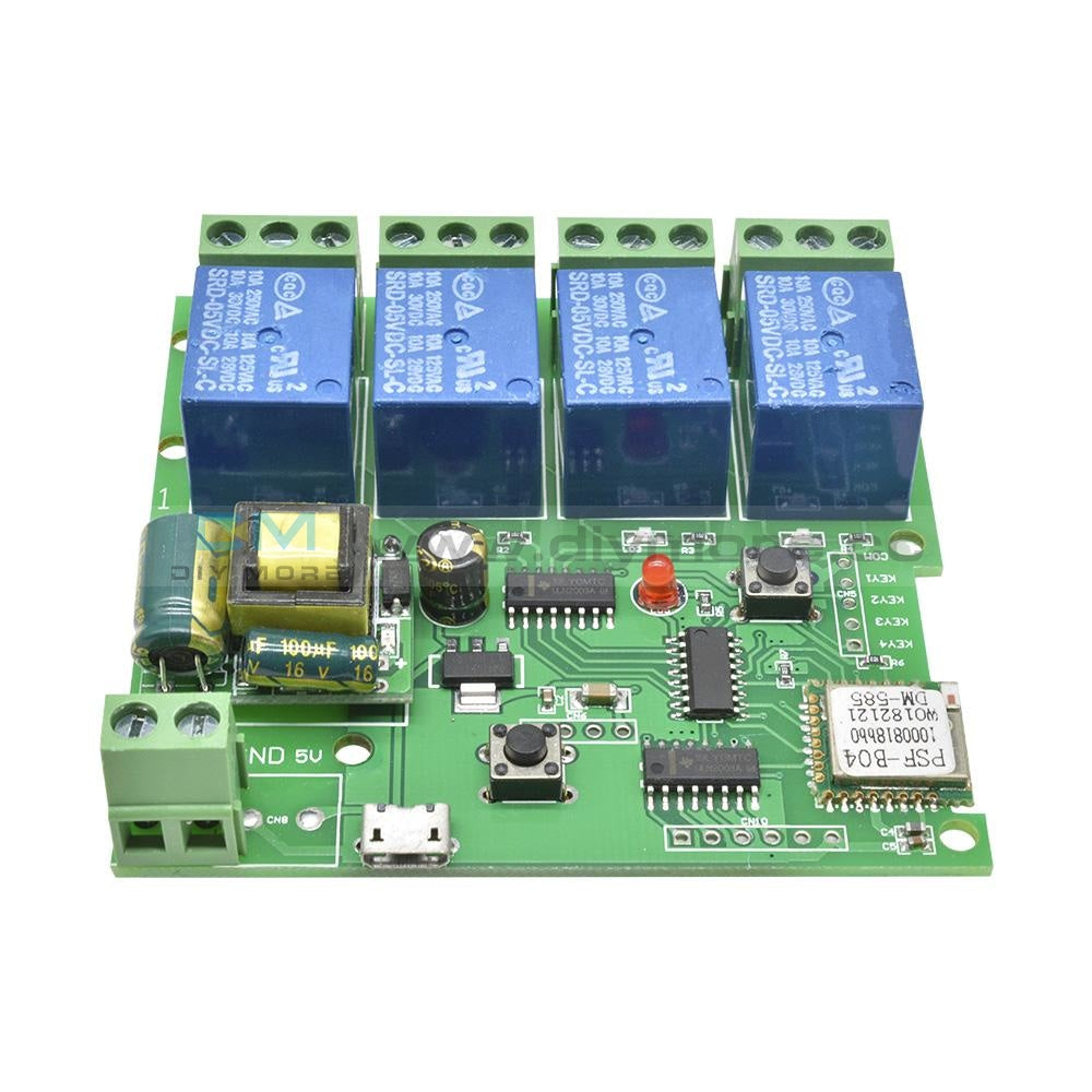
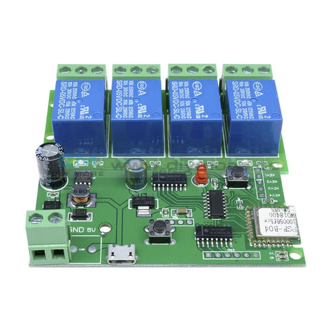
- Elsay four-way Modbus relay module is equipped with mature and stable 8-bit MCU and RS485 level communication chip. Using standard MODBUS RTU format RS485 communication protocol, it can realize 4 input signal detection and 4 relay output, which can be used for digital detection or power control occasions.
- Onboard mature and stable 8bit MCU and MAX485 level conversion chip;
- Communication protocol: support standard Modbus RTU protocol;
- Communication interface: support RS485/TTL UART interface;
- Communication baud rate: 4800/9600/19200, the default is 9600bps, and it supports power-off save;
- Optocoupler input signal range: DC3.3-30V (this input cannot be used for relay control);
- Output signal: relay switch signal, support manual, flash off, flash off mode, flash off/flash off delay base is 0.1S, the maximum flash off/flash off time can be set to 0xFFFF*0.1S=6553.5S;
- Device address: range 1-255, default 255, support power-off save;
- The baud rate, input signal, relay status, and device address can be read using software/commands;
- There are 4 5V, 10A/250V AC 10A/30V DC relays on board, which can be activated continuously for 100,000 times, with diode effusion protection, and short response time;
- On-board relay switch indicator;
- Power supply voltage: DC7-24V, support DC socket/5.08mm terminal power supply, with input anti-reverse protection;
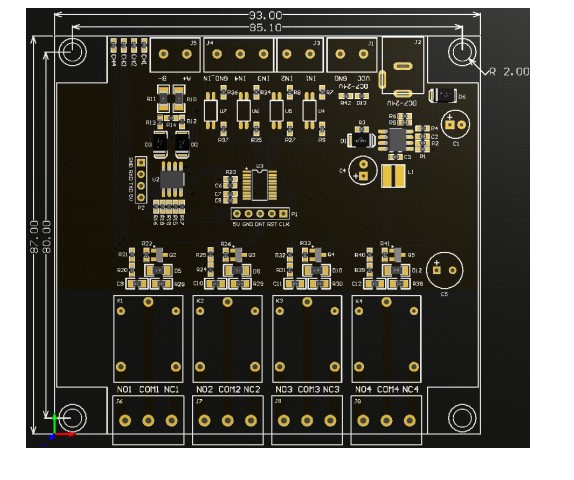
Hardware introduction and description
Board size
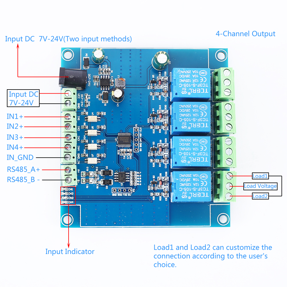
Interface introduction
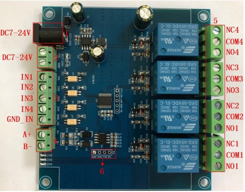
- DC-005 socket: DC7-24V power input socket;
- VCC, GND: DC7-24V 5.08mm power input terminal;
- DC3.3-30V optocoupler signal input:
- IN1: Channel 1 positive
- IN2: Channel 2 positive
- IN3: Channel 3 positive
- IN4: Channel 4 positive
- GND_IN: Common terminal negative
- A+, B-: RS485 communication interface, A+, B- are respectively connected to A+, B- of the external control terminal;
- NC: Normally closed terminal, the relay is short-connected with COM before it is closed, and it is suspended after it is closed;
- COM: public end;
- NO: Normally open end, the relay is suspended before closing, and shorted to COM after closing.
- 6, GND, RXD, TXD: TTL level UART communication interface, GND, RXD, TXD are respectively connected to GND, TXD, RXD of the external control terminal;
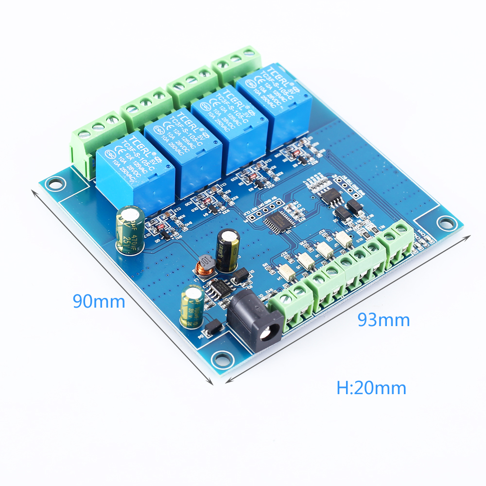
Product Parameters:
Modbus RTU Command:
Package Include:
- Item name: 4CH Modbus Relay Module
- Work voltage:DC 7V~24V
- Baud rate:4800/9600/19600bps(default 9600bps)
- Optocoupler input signal:DC 3.3V~30V
- Set address:1~255
- Relay contorl mode: ON/OFF,Delay_ON,Delay_OFF mode
- Delay time: 0~6553.5s
- Load: AC 250V 10A or DC 28V 10A
- Protocol:Modbus RTU
- Interface:RS485/TTL UART
- Control channel: 4channel
- Operating Temperature:-20℃~85℃
- Operating Humidity:5%~95%RH
- Module Size:93*90*20mm
Modbus RTU Command:
- Suppose the device address is 0xFF so return 00 10 00 00 00 01 02 00 FF EB 80 and the 9th btye is device address.
- Turn ON CH_1 Relay(Normal Mode):
- Send: FF 05 00 00 FF 00 99 E4
- Return: FF 05 00 00 FF 00 99 E4
- Note_1:The 3rd and 4th byte are relay addresses.So it can be 0x0000,0x0001,0x0002,0x0003.
- Note_2:The 5th and 6th byte are relay data.0xFF00 means turn ON relay and 0x0000 means turn OFF relay.
- Turn OFF CH_1 Relay(Normal Mode):
- Send: FF 05 00 00 00 00 D8 14
- Return: FF 05 00 00 00 00 D8 14
- Turn ON CH_2 Relay(Normal Mode):
- Send: FF 05 00 01 FF 00 C8 24
- Return: FF 05 00 01 FF 00 C8 24
- Turn OFF CH_2 Relay(Normal Mode):
- Send: FF 05 00 01 00 00 89 D4
- Return: FF 05 00 01 00 00 89 D4
- Turn ON All relays:
- Send: FF 0F 00 00 00 08 01 FF 30 1D
- Return: FF 0F 00 00 00 08 41 D3
- Turn OFF All relays:
- Send: FF 0F 00 00 00 08 01 00 70 5D
- Return: FF 0F 00 00 00 08 41 D3
- Set device address to 0x01:
- Send: 00 10 00 00 00 01 02 00 01 6A 00
- Return: 00 10 00 00 00 01 02 00 01 6A 00
- Note: The 9th btye is device address.
- Set device address to 0xFF:
- Send: 00 10 00 00 00 01 02 00 FF EB 80
- Return: 00 10 00 00 00 01 02 00 FF EB 80
- Read device address:
- Send: 00 03 00 00 00 01 85 DB
- Return: 00 03 02 00 FF C5 C4
- Note: The 5th btye is device address.
- Read relay status:
- Send: FF 01 00 00 00 08 28 12
- Return: FF 01 01 01 A1 A0
- Note:The 4th means which one relay.0 means OFF and 1 means ON.
- Read optocoupler input staturs:
- Send: FF 02 00 00 00 08 6C 12
- Return: FF 02 01 01 51 A0
- Note:The 4th means which one input.0 means low level signal input and 1 means high level signal input.
- Set baud rate 4800bps:
- Send: FF 10 03 E9 00 01 02 00 02 4A 0C
- Return: FF 10 03 E9 00 01 C5 A7
- Note:The 9th btye is baud rate value.0x02 is 4800bps.0x03 is 9600bps.0x04 is 19200bps.
- Set baud rate 9600bps:
- Send: FF 10 03 E9 00 01 02 00 03 8B CC
- Return: FF 10 03 E9 00 01 C5 A7
- Set baud rate 19200bps:
- Send: FF 10 03 E9 00 01 02 00 04 CA 0E
- Return: FF 10 03 E9 00 01 C5 A7
- Turn ON CH_1 Relay(2S Flashing Mode):
- Send: FF 10 00 03 00 02 04 00 04 00 14 C5 9F
- Return: FF 10 00 03 00 02 A4 16
- Note_1:The 3rd and 4th byte are relay addresses.So CH1~CH4 can be 0x0003,0x0008,0x000D,0x0012.
- Note_2:The 10th and 11th byte are delay time in second.The minimum delay time is 0.1s.Relay will OFF after delay time.So the delay time in this command is : 0x0014*0.1=2S.
- Turn OFF CH_1 Relay(3S Flashing Mode):
- Send: FF 10 00 03 00 02 04 00 02 00 1E A5 99
- Return: FF 10 00 03 00 02 A4 16
- Note:Relay will ON after delay time.So the delay time in this command is : 0x001E*0.1=3S.
Package Include:
- 1PC 4CH Modbus Relay Module
Purchasing & Delivery
Before you make your purchase, it’s helpful to know the measurements of the area you plan to place the furniture. You should also measure any doorways and hallways through which the furniture will pass to get to its final destination.Picking up at the store
Shopify Shop requires that all products are properly inspected BEFORE you take it home to insure there are no surprises. Our team is happy to open all packages and will assist in the inspection process. We will then reseal packages for safe transport. We encourage all customers to bring furniture pads or blankets to protect the items during transport as well as rope or tie downs. Shopify Shop will not be responsible for damage that occurs after leaving the store or during transit. It is the purchaser’s responsibility to make sure the correct items are picked up and in good condition.Delivery
Customers are able to pick the next available delivery day that best fits their schedule. However, to route stops as efficiently as possible, Shopify Shop will provide the time frame. Customers will not be able to choose a time. You will be notified in advance of your scheduled time frame. Please make sure that a responsible adult (18 years or older) will be home at that time.In preparation for your delivery, please remove existing furniture, pictures, mirrors, accessories, etc. to prevent damages. Also insure that the area where you would like your furniture placed is clear of any old furniture and any other items that may obstruct the passageway of the delivery team. Shopify Shop will deliver, assemble, and set-up your new furniture purchase and remove all packing materials from your home. Our delivery crews are not permitted to move your existing furniture or other household items. Delivery personnel will attempt to deliver the purchased items in a safe and controlled manner but will not attempt to place furniture if they feel it will result in damage to the product or your home. Delivery personnel are unable to remove doors, hoist furniture or carry furniture up more than 3 flights of stairs. An elevator must be available for deliveries to the 4th floor and above.
Other Customers also buy:
-
 Translation missing: en.products.product.regular_price $13.99{"id":4896534233159,"title":"DC 24V 4 Channel Relay Control Switch RS485\/TTL Anti-reverse Connection Module","handle":"dc-24v-4-channel-relay-control-switch-rs485-ttl-anti-reverse-connection-module","description":"\u003cdiv data-mce-fragment=\"1\"\u003e\u003cspan lang=\"en\" data-mce-fragment=\"1\"\u003e\u003cstrong data-mce-fragment=\"1\"\u003eOverview:\u003c\/strong\u003e\u003c\/span\u003e\u003c\/div\u003e\n\u003cdiv data-mce-fragment=\"1\"\u003e\n\u003cul\u003e\n\u003cli\u003e\u003cspan lang=\"en\" data-mce-fragment=\"1\"\u003eElsay four-way Modbus relay module is equipped with mature and stable 8-bit MCU and RS485 level communication chip. Using standard MODBUS RTU format RS485 communication protocol, it can realize 4 input signal detection and 4 relay output, which can be used for digital detection or power control occasions.\u003c\/span\u003e\u003c\/li\u003e\n\u003c\/ul\u003e\n\u003cspan lang=\"en\" data-mce-fragment=\"1\"\u003e\u003cspan lang=\"en\" data-mce-fragment=\"1\"\u003e\u003cstrong data-mce-fragment=\"1\"\u003eFeatures:\u003c\/strong\u003e\u003cbr data-mce-fragment=\"1\"\u003e\u003c\/span\u003e\u003c\/span\u003e\n\u003cul\u003e\n\u003cli\u003e\u003cspan lang=\"en\" data-mce-fragment=\"1\"\u003eOnboard mature and stable 8bit MCU and MAX485 level conversion chip;\u003c\/span\u003e\u003c\/li\u003e\n\u003cli\u003e\u003cspan lang=\"en\" data-mce-fragment=\"1\"\u003eCommunication protocol: support standard Modbus RTU protocol;\u003c\/span\u003e\u003c\/li\u003e\n\u003cli\u003e\u003cspan lang=\"en\" data-mce-fragment=\"1\"\u003eCommunication interface: support RS485\/TTL UART interface;\u003c\/span\u003e\u003c\/li\u003e\n\u003cli\u003e\u003cspan lang=\"en\" data-mce-fragment=\"1\"\u003eCommunication baud rate: 4800\/9600\/19200, the default is 9600bps, and it supports power-off save;\u003c\/span\u003e\u003c\/li\u003e\n\u003cli\u003e\u003cspan lang=\"en\" data-mce-fragment=\"1\"\u003eOptocoupler input signal range: DC3.3-30V (this input cannot be used for relay control);\u003c\/span\u003e\u003c\/li\u003e\n\u003cli\u003e\u003cspan lang=\"en\" data-mce-fragment=\"1\"\u003eOutput signal: relay switch signal, support manual, flash off, flash off mode, flash off\/flash off delay base is 0.1S, the maximum flash off\/flash off time can be set to 0xFFFF*0.1S=6553.5S;\u003c\/span\u003e\u003c\/li\u003e\n\u003cli\u003e\u003cspan lang=\"en\" data-mce-fragment=\"1\"\u003eDevice address: range 1-255, default 255, support power-off save;\u003c\/span\u003e\u003c\/li\u003e\n\u003cli\u003e\u003cspan lang=\"en\" data-mce-fragment=\"1\"\u003eThe baud rate, input signal, relay status, and device address can be read using software\/commands;\u003c\/span\u003e\u003c\/li\u003e\n\u003cli\u003e\u003cspan lang=\"en\" data-mce-fragment=\"1\"\u003eThere are 4 5V, 10A\/250V AC 10A\/30V DC relays on board, which can be activated continuously for 100,000 times, with diode effusion protection, and short response time;\u003c\/span\u003e\u003c\/li\u003e\n\u003cli\u003e\u003cspan lang=\"en\" data-mce-fragment=\"1\"\u003eOn-board relay switch indicator;\u003c\/span\u003e\u003c\/li\u003e\n\u003cli\u003e\u003cspan lang=\"en\" data-mce-fragment=\"1\"\u003ePower supply voltage: DC7-24V, support DC socket\/5.08mm terminal power supply, with input anti-reverse protection;\u003c\/span\u003e\u003c\/li\u003e\n\u003c\/ul\u003e\n\u003c\/div\u003e\n\u003cdiv data-mce-fragment=\"1\"\u003e\u003cspan data-mce-fragment=\"1\"\u003e\u003cstrong data-mce-fragment=\"1\"\u003e\u003cspan lang=\"en\" data-mce-fragment=\"1\"\u003e\u003cspan title=\"\" data-mce-fragment=\"1\"\u003eHardware introduction and description\u003c\/span\u003e\u003c\/span\u003e\u003c\/strong\u003e\u003c\/span\u003e\u003c\/div\u003e\n\u003cdiv data-mce-fragment=\"1\"\u003e\u003cspan lang=\"en\" data-mce-fragment=\"1\"\u003e\u003cspan title=\"\" data-mce-fragment=\"1\"\u003eBoard size\u003c\/span\u003e\u003c\/span\u003e\u003c\/div\u003e\n\u003cdiv data-mce-fragment=\"1\"\u003e\u003cspan lang=\"en\" data-mce-fragment=\"1\"\u003e\u003cspan title=\"\" data-mce-fragment=\"1\"\u003e\u003cimg src=\"https:\/\/pg-cdn-a2.datacaciques.com\/00\/NDAy\/20\/10\/27\/759miw180130a6g1\/f50580d1c231c450.jpg\" data-mce-fragment=\"1\" data-mce-src=\"https:\/\/pg-cdn-a2.datacaciques.com\/00\/NDAy\/20\/10\/27\/759miw180130a6g1\/f50580d1c231c450.jpg\"\u003e\u003c\/span\u003e\u003c\/span\u003e\u003c\/div\u003e\n\u003cdiv data-mce-fragment=\"1\"\u003e\u003cspan lang=\"en\" data-mce-fragment=\"1\"\u003e\u003cspan title=\"\" data-mce-fragment=\"1\"\u003eInterface introduction\u003c\/span\u003e\u003c\/span\u003e\u003c\/div\u003e\n\u003cdiv data-mce-fragment=\"1\"\u003e\u003cspan lang=\"en\" data-mce-fragment=\"1\"\u003e\u003cspan title=\"\" data-mce-fragment=\"1\"\u003e\u003cimg src=\"https:\/\/pg-cdn-a2.datacaciques.com\/00\/NDAy\/20\/10\/27\/759miw180130a6g1\/4bc7a5d2ad0c45a2.jpg\" data-mce-fragment=\"1\" data-mce-src=\"https:\/\/pg-cdn-a2.datacaciques.com\/00\/NDAy\/20\/10\/27\/759miw180130a6g1\/4bc7a5d2ad0c45a2.jpg\"\u003e\u003c\/span\u003e\u003c\/span\u003e\u003c\/div\u003e\n\u003cdiv data-mce-fragment=\"1\"\u003e\n\u003cul\u003e\n\u003cli\u003e\u003cspan lang=\"en\" data-mce-fragment=\"1\"\u003e\u003cspan title=\"\" data-mce-fragment=\"1\"\u003eDC-005 socket: DC7-24V power input socket;\u003c\/span\u003e\u003c\/span\u003e\u003c\/li\u003e\n\u003cli\u003e\u003cspan lang=\"en\" data-mce-fragment=\"1\"\u003e\u003cspan title=\"\" data-mce-fragment=\"1\"\u003eVCC, GND: DC7-24V 5.08mm power input terminal;\u003c\/span\u003e\u003c\/span\u003e\u003c\/li\u003e\n\u003cli\u003e\u003cspan lang=\"en\" data-mce-fragment=\"1\"\u003e\u003cspan title=\"\" data-mce-fragment=\"1\"\u003eDC3.3-30V optocoupler signal input:\u003c\/span\u003e\u003c\/span\u003e\u003c\/li\u003e\n\u003cli\u003e\u003cspan lang=\"en\" data-mce-fragment=\"1\"\u003e\u003cspan title=\"\" data-mce-fragment=\"1\"\u003eIN1: Channel 1 positive\u003c\/span\u003e\u003c\/span\u003e\u003c\/li\u003e\n\u003cli\u003e\u003cspan lang=\"en\" data-mce-fragment=\"1\"\u003e\u003cspan title=\"\" data-mce-fragment=\"1\"\u003eIN2: Channel 2 positive\u003c\/span\u003e\u003c\/span\u003e\u003c\/li\u003e\n\u003cli\u003e\u003cspan lang=\"en\" data-mce-fragment=\"1\"\u003e\u003cspan title=\"\" data-mce-fragment=\"1\"\u003eIN3: Channel 3 positive\u003c\/span\u003e\u003c\/span\u003e\u003c\/li\u003e\n\u003cli\u003e\u003cspan lang=\"en\" data-mce-fragment=\"1\"\u003e\u003cspan title=\"\" data-mce-fragment=\"1\"\u003eIN4: Channel 4 positive\u003c\/span\u003e\u003c\/span\u003e\u003c\/li\u003e\n\u003cli\u003e\u003cspan lang=\"en\" data-mce-fragment=\"1\"\u003e\u003cspan title=\"\" data-mce-fragment=\"1\"\u003eGND_IN: Common terminal negative\u003c\/span\u003e\u003c\/span\u003e\u003c\/li\u003e\n\u003cli\u003e\u003cspan lang=\"en\" data-mce-fragment=\"1\"\u003e\u003cspan title=\"\" data-mce-fragment=\"1\"\u003eA+, B-: RS485 communication interface, A+, B- are respectively connected to A+, B- of the external control terminal;\u003c\/span\u003e\u003c\/span\u003e\u003c\/li\u003e\n\u003c\/ul\u003e\n\u003cspan lang=\"en\" data-mce-fragment=\"1\"\u003e\u003cspan lang=\"en\" data-mce-fragment=\"1\"\u003e\u003cspan title=\"\" data-mce-fragment=\"1\"\u003e\u003cstrong\u003eRelay switch signal output:\u003c\/strong\u003e\u003cbr data-mce-fragment=\"1\"\u003e\u003c\/span\u003e\u003c\/span\u003e\u003c\/span\u003e\n\u003cul\u003e\n\u003cli\u003e\u003cspan lang=\"en\" data-mce-fragment=\"1\"\u003e\u003cspan title=\"\" data-mce-fragment=\"1\"\u003eNC: Normally closed terminal, the relay is short-connected with COM before it is closed, and it is suspended after it is closed;\u003c\/span\u003e\u003c\/span\u003e\u003c\/li\u003e\n\u003cli\u003e\u003cspan lang=\"en\" data-mce-fragment=\"1\"\u003e\u003cspan title=\"\" data-mce-fragment=\"1\"\u003eCOM: public end;\u003c\/span\u003e\u003c\/span\u003e\u003c\/li\u003e\n\u003cli\u003e\u003cspan lang=\"en\" data-mce-fragment=\"1\"\u003e\u003cspan title=\"\" data-mce-fragment=\"1\"\u003eNO: Normally open end, the relay is suspended before closing, and shorted to COM after closing.\u003c\/span\u003e\u003c\/span\u003e\u003c\/li\u003e\n\u003cli\u003e\u003cspan lang=\"en\" data-mce-fragment=\"1\"\u003e\u003cspan title=\"\" data-mce-fragment=\"1\"\u003e6, GND, RXD, TXD: TTL level UART communication interface, GND, RXD, TXD are respectively connected to GND, TXD, RXD of the external control terminal;\u003c\/span\u003e\u003c\/span\u003e\u003c\/li\u003e\n\u003c\/ul\u003e\n\u003c\/div\u003e\n\u003cdiv data-mce-fragment=\"1\"\u003e\n\u003cspan lang=\"en\" data-mce-fragment=\"1\"\u003e\u003cspan lang=\"en\" data-mce-fragment=\"1\"\u003e\u003cspan title=\"\" data-mce-fragment=\"1\"\u003e\u003cstrong data-mce-fragment=\"1\"\u003eProduct Parameters:\u003c\/strong\u003e\u003cbr data-mce-fragment=\"1\"\u003e\u003c\/span\u003e\u003c\/span\u003e\u003c\/span\u003e\n\u003cul\u003e\n\u003cli\u003e\u003cspan lang=\"en\" data-mce-fragment=\"1\"\u003e\u003cspan title=\"\" data-mce-fragment=\"1\"\u003eItem name: 4CH Modbus Relay Module \u003c\/span\u003e\u003c\/span\u003e\u003c\/li\u003e\n\u003cli\u003e\u003cspan lang=\"en\" data-mce-fragment=\"1\"\u003e\u003cspan title=\"\" data-mce-fragment=\"1\"\u003eWork voltage:DC 7V~24V\u003c\/span\u003e\u003c\/span\u003e\u003c\/li\u003e\n\u003cli\u003e\u003cspan lang=\"en\" data-mce-fragment=\"1\"\u003e\u003cspan title=\"\" data-mce-fragment=\"1\"\u003eBaud rate:4800\/9600\/19600bps(default 9600bps)\u003c\/span\u003e\u003c\/span\u003e\u003c\/li\u003e\n\u003cli\u003e\u003cspan lang=\"en\" data-mce-fragment=\"1\"\u003e\u003cspan title=\"\" data-mce-fragment=\"1\"\u003eOptocoupler input signal:DC 3.3V~30V\u003c\/span\u003e\u003c\/span\u003e\u003c\/li\u003e\n\u003cli\u003e\u003cspan lang=\"en\" data-mce-fragment=\"1\"\u003e\u003cspan title=\"\" data-mce-fragment=\"1\"\u003eSet address:1~255\u003c\/span\u003e\u003c\/span\u003e\u003c\/li\u003e\n\u003cli\u003e\u003cspan lang=\"en\" data-mce-fragment=\"1\"\u003e\u003cspan title=\"\" data-mce-fragment=\"1\"\u003eRelay contorl mode: ON\/OFF,Delay_ON,Delay_OFF mode\u003c\/span\u003e\u003c\/span\u003e\u003c\/li\u003e\n\u003cli\u003e\u003cspan lang=\"en\" data-mce-fragment=\"1\"\u003e\u003cspan title=\"\" data-mce-fragment=\"1\"\u003eDelay time: 0~6553.5s \u003c\/span\u003e\u003c\/span\u003e\u003c\/li\u003e\n\u003cli\u003e\u003cspan lang=\"en\" data-mce-fragment=\"1\"\u003e\u003cspan title=\"\" data-mce-fragment=\"1\"\u003eLoad: AC 250V 10A or DC 28V 10A\u003c\/span\u003e\u003c\/span\u003e\u003c\/li\u003e\n\u003cli\u003e\u003cspan lang=\"en\" data-mce-fragment=\"1\"\u003e\u003cspan title=\"\" data-mce-fragment=\"1\"\u003eProtocol:Modbus RTU\u003c\/span\u003e\u003c\/span\u003e\u003c\/li\u003e\n\u003cli\u003e\u003cspan lang=\"en\" data-mce-fragment=\"1\"\u003e\u003cspan title=\"\" data-mce-fragment=\"1\"\u003eInterface:RS485\/TTL UART\u003c\/span\u003e\u003c\/span\u003e\u003c\/li\u003e\n\u003cli\u003e\u003cspan lang=\"en\" data-mce-fragment=\"1\"\u003e\u003cspan title=\"\" data-mce-fragment=\"1\"\u003eControl channel: 4channel\u003c\/span\u003e\u003c\/span\u003e\u003c\/li\u003e\n\u003cli\u003e\u003cspan lang=\"en\" data-mce-fragment=\"1\"\u003e\u003cspan title=\"\" data-mce-fragment=\"1\"\u003eOperating Temperature:-20℃~85℃\u003c\/span\u003e\u003c\/span\u003e\u003c\/li\u003e\n\u003cli\u003e\u003cspan lang=\"en\" data-mce-fragment=\"1\"\u003e\u003cspan title=\"\" data-mce-fragment=\"1\"\u003eOperating Humidity:5%~95%RH\u003c\/span\u003e\u003c\/span\u003e\u003c\/li\u003e\n\u003cli\u003e\u003cspan lang=\"en\" data-mce-fragment=\"1\"\u003e\u003cspan title=\"\" data-mce-fragment=\"1\"\u003eModule Size:93*90*20mm\u003c\/span\u003e\u003c\/span\u003e\u003c\/li\u003e\n\u003c\/ul\u003e\n\u003cspan lang=\"en\" data-mce-fragment=\"1\"\u003e\u003cspan lang=\"en\" data-mce-fragment=\"1\"\u003e\u003cspan title=\"\" data-mce-fragment=\"1\"\u003e\u003cimg src=\"https:\/\/pg-cdn-a2.datacaciques.com\/00\/NDAy\/20\/10\/27\/759miw180130a6g1\/5a40dd1349231871.jpg\" data-mce-fragment=\"1\" data-mce-src=\"https:\/\/pg-cdn-a2.datacaciques.com\/00\/NDAy\/20\/10\/27\/759miw180130a6g1\/5a40dd1349231871.jpg\"\u003e\u003cbr data-mce-fragment=\"1\"\u003e\u003cstrong data-mce-fragment=\"1\"\u003eModbus RTU Command:\u003c\/strong\u003e\u003cbr data-mce-fragment=\"1\"\u003e\u003c\/span\u003e\u003c\/span\u003e\u003c\/span\u003e\n\u003cul\u003e\n\u003cli\u003e\u003cspan lang=\"en\" data-mce-fragment=\"1\"\u003e\u003cspan title=\"\" data-mce-fragment=\"1\"\u003eSuppose the device address is 0xFF so return 00 10 00 00 00 01 02 00 FF EB 80 and the 9th btye is device address.\u003c\/span\u003e\u003c\/span\u003e\u003c\/li\u003e\n\u003cli\u003e\u003cspan lang=\"en\" data-mce-fragment=\"1\"\u003e\u003cspan title=\"\" data-mce-fragment=\"1\"\u003eTurn ON CH_1 Relay(Normal Mode):\u003c\/span\u003e\u003c\/span\u003e\u003c\/li\u003e\n\u003cli\u003e\u003cspan lang=\"en\" data-mce-fragment=\"1\"\u003e\u003cspan title=\"\" data-mce-fragment=\"1\"\u003e Send: FF 05 00 00 FF 00 99 E4\u003c\/span\u003e\u003c\/span\u003e\u003c\/li\u003e\n\u003cli\u003e\u003cspan lang=\"en\" data-mce-fragment=\"1\"\u003e\u003cspan title=\"\" data-mce-fragment=\"1\"\u003e Return: FF 05 00 00 FF 00 99 E4\u003c\/span\u003e\u003c\/span\u003e\u003c\/li\u003e\n\u003cli\u003e\u003cspan lang=\"en\" data-mce-fragment=\"1\"\u003e\u003cspan title=\"\" data-mce-fragment=\"1\"\u003e Note_1:The 3rd and 4th byte are relay addresses.So it can be 0x0000,0x0001,0x0002,0x0003.\u003c\/span\u003e\u003c\/span\u003e\u003c\/li\u003e\n\u003cli\u003e\u003cspan lang=\"en\" data-mce-fragment=\"1\"\u003e\u003cspan title=\"\" data-mce-fragment=\"1\"\u003e Note_2:The 5th and 6th byte are relay data.0xFF00 means turn ON relay and 0x0000 means turn OFF relay.\u003c\/span\u003e\u003c\/span\u003e\u003c\/li\u003e\n\u003cli\u003e\u003cspan lang=\"en\" data-mce-fragment=\"1\"\u003e\u003cspan title=\"\" data-mce-fragment=\"1\"\u003eTurn OFF CH_1 Relay(Normal Mode):\u003c\/span\u003e\u003c\/span\u003e\u003c\/li\u003e\n\u003cli\u003e\u003cspan lang=\"en\" data-mce-fragment=\"1\"\u003e\u003cspan title=\"\" data-mce-fragment=\"1\"\u003e Send: FF 05 00 00 00 00 D8 14\u003c\/span\u003e\u003c\/span\u003e\u003c\/li\u003e\n\u003cli\u003e\u003cspan lang=\"en\" data-mce-fragment=\"1\"\u003e\u003cspan title=\"\" data-mce-fragment=\"1\"\u003e Return: FF 05 00 00 00 00 D8 14\u003c\/span\u003e\u003c\/span\u003e\u003c\/li\u003e\n\u003cli\u003e\u003cspan lang=\"en\" data-mce-fragment=\"1\"\u003e\u003cspan title=\"\" data-mce-fragment=\"1\"\u003eTurn ON CH_2 Relay(Normal Mode):\u003c\/span\u003e\u003c\/span\u003e\u003c\/li\u003e\n\u003cli\u003e\u003cspan lang=\"en\" data-mce-fragment=\"1\"\u003e\u003cspan title=\"\" data-mce-fragment=\"1\"\u003e Send: FF 05 00 01 FF 00 C8 24\u003c\/span\u003e\u003c\/span\u003e\u003c\/li\u003e\n\u003cli\u003e\u003cspan lang=\"en\" data-mce-fragment=\"1\"\u003e\u003cspan title=\"\" data-mce-fragment=\"1\"\u003e Return: FF 05 00 01 FF 00 C8 24\u003c\/span\u003e\u003c\/span\u003e\u003c\/li\u003e\n\u003cli\u003e\u003cspan lang=\"en\" data-mce-fragment=\"1\"\u003e\u003cspan title=\"\" data-mce-fragment=\"1\"\u003eTurn OFF CH_2 Relay(Normal Mode):\u003c\/span\u003e\u003c\/span\u003e\u003c\/li\u003e\n\u003cli\u003e\u003cspan lang=\"en\" data-mce-fragment=\"1\"\u003e\u003cspan title=\"\" data-mce-fragment=\"1\"\u003e Send: FF 05 00 01 00 00 89 D4\u003c\/span\u003e\u003c\/span\u003e\u003c\/li\u003e\n\u003cli\u003e\u003cspan lang=\"en\" data-mce-fragment=\"1\"\u003e\u003cspan title=\"\" data-mce-fragment=\"1\"\u003e Return: FF 05 00 01 00 00 89 D4\u003c\/span\u003e\u003c\/span\u003e\u003c\/li\u003e\n\u003cli\u003e\u003cspan lang=\"en\" data-mce-fragment=\"1\"\u003e\u003cspan title=\"\" data-mce-fragment=\"1\"\u003eTurn ON All relays:\u003c\/span\u003e\u003c\/span\u003e\u003c\/li\u003e\n\u003cli\u003e\u003cspan lang=\"en\" data-mce-fragment=\"1\"\u003e\u003cspan title=\"\" data-mce-fragment=\"1\"\u003e Send: FF 0F 00 00 00 08 01 FF 30 1D\u003c\/span\u003e\u003c\/span\u003e\u003c\/li\u003e\n\u003cli\u003e\u003cspan lang=\"en\" data-mce-fragment=\"1\"\u003e\u003cspan title=\"\" data-mce-fragment=\"1\"\u003e Return: FF 0F 00 00 00 08 41 D3\u003c\/span\u003e\u003c\/span\u003e\u003c\/li\u003e\n\u003cli\u003e\u003cspan lang=\"en\" data-mce-fragment=\"1\"\u003e\u003cspan title=\"\" data-mce-fragment=\"1\"\u003eTurn OFF All relays:\u003c\/span\u003e\u003c\/span\u003e\u003c\/li\u003e\n\u003cli\u003e\u003cspan lang=\"en\" data-mce-fragment=\"1\"\u003e\u003cspan title=\"\" data-mce-fragment=\"1\"\u003e Send: FF 0F 00 00 00 08 01 00 70 5D\u003c\/span\u003e\u003c\/span\u003e\u003c\/li\u003e\n\u003cli\u003e\u003cspan lang=\"en\" data-mce-fragment=\"1\"\u003e\u003cspan title=\"\" data-mce-fragment=\"1\"\u003e Return: FF 0F 00 00 00 08 41 D3\u003c\/span\u003e\u003c\/span\u003e\u003c\/li\u003e\n\u003cli\u003e\u003cspan lang=\"en\" data-mce-fragment=\"1\"\u003e\u003cspan title=\"\" data-mce-fragment=\"1\"\u003eSet device address to 0x01:\u003c\/span\u003e\u003c\/span\u003e\u003c\/li\u003e\n\u003cli\u003e\u003cspan lang=\"en\" data-mce-fragment=\"1\"\u003e\u003cspan title=\"\" data-mce-fragment=\"1\"\u003e Send: 00 10 00 00 00 01 02 00 01 6A 00\u003c\/span\u003e\u003c\/span\u003e\u003c\/li\u003e\n\u003cli\u003e\u003cspan lang=\"en\" data-mce-fragment=\"1\"\u003e\u003cspan title=\"\" data-mce-fragment=\"1\"\u003e Return: 00 10 00 00 00 01 02 00 01 6A 00\u003c\/span\u003e\u003c\/span\u003e\u003c\/li\u003e\n\u003cli\u003e\u003cspan lang=\"en\" data-mce-fragment=\"1\"\u003e\u003cspan title=\"\" data-mce-fragment=\"1\"\u003e Note: The 9th btye is device address.\u003c\/span\u003e\u003c\/span\u003e\u003c\/li\u003e\n\u003cli\u003e\u003cspan lang=\"en\" data-mce-fragment=\"1\"\u003e\u003cspan title=\"\" data-mce-fragment=\"1\"\u003eSet device address to 0xFF:\u003c\/span\u003e\u003c\/span\u003e\u003c\/li\u003e\n\u003cli\u003e\u003cspan lang=\"en\" data-mce-fragment=\"1\"\u003e\u003cspan title=\"\" data-mce-fragment=\"1\"\u003e Send: 00 10 00 00 00 01 02 00 FF EB 80\u003c\/span\u003e\u003c\/span\u003e\u003c\/li\u003e\n\u003cli\u003e\u003cspan lang=\"en\" data-mce-fragment=\"1\"\u003e\u003cspan title=\"\" data-mce-fragment=\"1\"\u003e Return: 00 10 00 00 00 01 02 00 FF EB 80\u003c\/span\u003e\u003c\/span\u003e\u003c\/li\u003e\n\u003cli\u003e\u003cspan lang=\"en\" data-mce-fragment=\"1\"\u003e\u003cspan title=\"\" data-mce-fragment=\"1\"\u003eRead device address:\u003c\/span\u003e\u003c\/span\u003e\u003c\/li\u003e\n\u003cli\u003e\u003cspan lang=\"en\" data-mce-fragment=\"1\"\u003e\u003cspan title=\"\" data-mce-fragment=\"1\"\u003e Send: 00 03 00 00 00 01 85 DB\u003c\/span\u003e\u003c\/span\u003e\u003c\/li\u003e\n\u003cli\u003e\u003cspan lang=\"en\" data-mce-fragment=\"1\"\u003e\u003cspan title=\"\" data-mce-fragment=\"1\"\u003e Return: 00 03 02 00 FF C5 C4\u003c\/span\u003e\u003c\/span\u003e\u003c\/li\u003e\n\u003cli\u003e\u003cspan lang=\"en\" data-mce-fragment=\"1\"\u003e\u003cspan title=\"\" data-mce-fragment=\"1\"\u003e Note: The 5th btye is device address.\u003c\/span\u003e\u003c\/span\u003e\u003c\/li\u003e\n\u003cli\u003e\u003cspan lang=\"en\" data-mce-fragment=\"1\"\u003e\u003cspan title=\"\" data-mce-fragment=\"1\"\u003eRead relay status:\u003c\/span\u003e\u003c\/span\u003e\u003c\/li\u003e\n\u003cli\u003e\u003cspan lang=\"en\" data-mce-fragment=\"1\"\u003e\u003cspan title=\"\" data-mce-fragment=\"1\"\u003e Send: FF 01 00 00 00 08 28 12\u003c\/span\u003e\u003c\/span\u003e\u003c\/li\u003e\n\u003cli\u003e\u003cspan lang=\"en\" data-mce-fragment=\"1\"\u003e\u003cspan title=\"\" data-mce-fragment=\"1\"\u003e Return: FF 01 01 01 A1 A0\u003c\/span\u003e\u003c\/span\u003e\u003c\/li\u003e\n\u003cli\u003e\u003cspan lang=\"en\" data-mce-fragment=\"1\"\u003e\u003cspan title=\"\" data-mce-fragment=\"1\"\u003e Note:The 4th means which one relay.0 means OFF and 1 means ON.\u003c\/span\u003e\u003c\/span\u003e\u003c\/li\u003e\n\u003cli\u003e\u003cspan lang=\"en\" data-mce-fragment=\"1\"\u003e\u003cspan title=\"\" data-mce-fragment=\"1\"\u003eRead optocoupler input staturs:\u003c\/span\u003e\u003c\/span\u003e\u003c\/li\u003e\n\u003cli\u003e\u003cspan lang=\"en\" data-mce-fragment=\"1\"\u003e\u003cspan title=\"\" data-mce-fragment=\"1\"\u003e Send: FF 02 00 00 00 08 6C 12\u003c\/span\u003e\u003c\/span\u003e\u003c\/li\u003e\n\u003cli\u003e\u003cspan lang=\"en\" data-mce-fragment=\"1\"\u003e\u003cspan title=\"\" data-mce-fragment=\"1\"\u003e Return: FF 02 01 01 51 A0\u003c\/span\u003e\u003c\/span\u003e\u003c\/li\u003e\n\u003cli\u003e\u003cspan lang=\"en\" data-mce-fragment=\"1\"\u003e\u003cspan title=\"\" data-mce-fragment=\"1\"\u003e Note:The 4th means which one input.0 means low level signal input and 1 means high level signal input.\u003c\/span\u003e\u003c\/span\u003e\u003c\/li\u003e\n\u003cli\u003e\u003cspan lang=\"en\" data-mce-fragment=\"1\"\u003e\u003cspan title=\"\" data-mce-fragment=\"1\"\u003eSet baud rate 4800bps:\u003c\/span\u003e\u003c\/span\u003e\u003c\/li\u003e\n\u003cli\u003e\u003cspan lang=\"en\" data-mce-fragment=\"1\"\u003e\u003cspan title=\"\" data-mce-fragment=\"1\"\u003e Send: FF 10 03 E9 00 01 02 00 02 4A 0C\u003c\/span\u003e\u003c\/span\u003e\u003c\/li\u003e\n\u003cli\u003e\u003cspan lang=\"en\" data-mce-fragment=\"1\"\u003e\u003cspan title=\"\" data-mce-fragment=\"1\"\u003e Return: FF 10 03 E9 00 01 C5 A7\u003c\/span\u003e\u003c\/span\u003e\u003c\/li\u003e\n\u003cli\u003e\u003cspan lang=\"en\" data-mce-fragment=\"1\"\u003e\u003cspan title=\"\" data-mce-fragment=\"1\"\u003e Note:The 9th btye is baud rate value.0x02 is 4800bps.0x03 is 9600bps.0x04 is 19200bps.\u003c\/span\u003e\u003c\/span\u003e\u003c\/li\u003e\n\u003cli\u003e\u003cspan lang=\"en\" data-mce-fragment=\"1\"\u003e\u003cspan title=\"\" data-mce-fragment=\"1\"\u003eSet baud rate 9600bps:\u003c\/span\u003e\u003c\/span\u003e\u003c\/li\u003e\n\u003cli\u003e\u003cspan lang=\"en\" data-mce-fragment=\"1\"\u003e\u003cspan title=\"\" data-mce-fragment=\"1\"\u003e Send: FF 10 03 E9 00 01 02 00 03 8B CC\u003c\/span\u003e\u003c\/span\u003e\u003c\/li\u003e\n\u003cli\u003e\u003cspan lang=\"en\" data-mce-fragment=\"1\"\u003e\u003cspan title=\"\" data-mce-fragment=\"1\"\u003e Return: FF 10 03 E9 00 01 C5 A7\u003c\/span\u003e\u003c\/span\u003e\u003c\/li\u003e\n\u003cli\u003e\u003cspan lang=\"en\" data-mce-fragment=\"1\"\u003e\u003cspan title=\"\" data-mce-fragment=\"1\"\u003eSet baud rate 19200bps:\u003c\/span\u003e\u003c\/span\u003e\u003c\/li\u003e\n\u003cli\u003e\u003cspan lang=\"en\" data-mce-fragment=\"1\"\u003e\u003cspan title=\"\" data-mce-fragment=\"1\"\u003e Send: FF 10 03 E9 00 01 02 00 04 CA 0E\u003c\/span\u003e\u003c\/span\u003e\u003c\/li\u003e\n\u003cli\u003e\u003cspan lang=\"en\" data-mce-fragment=\"1\"\u003e\u003cspan title=\"\" data-mce-fragment=\"1\"\u003e Return: FF 10 03 E9 00 01 C5 A7\u003c\/span\u003e\u003c\/span\u003e\u003c\/li\u003e\n\u003cli\u003e\u003cspan lang=\"en\" data-mce-fragment=\"1\"\u003e\u003cspan title=\"\" data-mce-fragment=\"1\"\u003eTurn ON CH_1 Relay(2S Flashing Mode):\u003c\/span\u003e\u003c\/span\u003e\u003c\/li\u003e\n\u003cli\u003e\u003cspan lang=\"en\" data-mce-fragment=\"1\"\u003e\u003cspan title=\"\" data-mce-fragment=\"1\"\u003e Send: FF 10 00 03 00 02 04 00 04 00 14 C5 9F\u003c\/span\u003e\u003c\/span\u003e\u003c\/li\u003e\n\u003cli\u003e\u003cspan lang=\"en\" data-mce-fragment=\"1\"\u003e\u003cspan title=\"\" data-mce-fragment=\"1\"\u003e Return: FF 10 00 03 00 02 A4 16\u003c\/span\u003e\u003c\/span\u003e\u003c\/li\u003e\n\u003cli\u003e\u003cspan lang=\"en\" data-mce-fragment=\"1\"\u003e\u003cspan title=\"\" data-mce-fragment=\"1\"\u003e Note_1:The 3rd and 4th byte are relay addresses.So CH1~CH4 can be 0x0003,0x0008,0x000D,0x0012.\u003c\/span\u003e\u003c\/span\u003e\u003c\/li\u003e\n\u003cli\u003e\u003cspan lang=\"en\" data-mce-fragment=\"1\"\u003e\u003cspan title=\"\" data-mce-fragment=\"1\"\u003e Note_2:The 10th and 11th byte are delay time in second.The minimum delay time is 0.1s.Relay will OFF after delay time.So the delay time in this command is : 0x0014*0.1=2S.\u003c\/span\u003e\u003c\/span\u003e\u003c\/li\u003e\n\u003cli\u003e\u003cspan lang=\"en\" data-mce-fragment=\"1\"\u003e\u003cspan title=\"\" data-mce-fragment=\"1\"\u003eTurn OFF CH_1 Relay(3S Flashing Mode):\u003c\/span\u003e\u003c\/span\u003e\u003c\/li\u003e\n\u003cli\u003e\u003cspan lang=\"en\" data-mce-fragment=\"1\"\u003e\u003cspan title=\"\" data-mce-fragment=\"1\"\u003e Send: FF 10 00 03 00 02 04 00 02 00 1E A5 99\u003c\/span\u003e\u003c\/span\u003e\u003c\/li\u003e\n\u003cli\u003e\u003cspan lang=\"en\" data-mce-fragment=\"1\"\u003e\u003cspan title=\"\" data-mce-fragment=\"1\"\u003e Return: FF 10 00 03 00 02 A4 16\u003c\/span\u003e\u003c\/span\u003e\u003c\/li\u003e\n\u003cli\u003e\u003cspan lang=\"en\" data-mce-fragment=\"1\"\u003e\u003cspan title=\"\" data-mce-fragment=\"1\"\u003e Note:Relay will ON after delay time.So the delay time in this command is : 0x001E*0.1=3S.\u003c\/span\u003e\u003c\/span\u003e\u003c\/li\u003e\n\u003c\/ul\u003e\n\u003cspan lang=\"en\" data-mce-fragment=\"1\"\u003e\u003cspan lang=\"en\" data-mce-fragment=\"1\"\u003e\u003cspan title=\"\" data-mce-fragment=\"1\"\u003e\u003cimg src=\"https:\/\/pg-cdn-a2.datacaciques.com\/00\/NDAy\/20\/10\/27\/759miw180130a6g1\/b4e1c2017abb1ec6.jpg\" data-mce-fragment=\"1\" data-mce-src=\"https:\/\/pg-cdn-a2.datacaciques.com\/00\/NDAy\/20\/10\/27\/759miw180130a6g1\/b4e1c2017abb1ec6.jpg\"\u003e\u003cbr data-mce-fragment=\"1\"\u003e\u003cstrong data-mce-fragment=\"1\"\u003ePackage Include:\u003c\/strong\u003e\u003cbr data-mce-fragment=\"1\"\u003e\u003c\/span\u003e\u003c\/span\u003e\u003c\/span\u003e\n\u003cul\u003e\n\u003cli\u003e\u003cspan lang=\"en\" data-mce-fragment=\"1\"\u003e\u003cspan title=\"\" data-mce-fragment=\"1\"\u003e 1PC 4CH Modbus Relay Module \u003c\/span\u003e\u003c\/span\u003e\u003c\/li\u003e\n\u003c\/ul\u003e\n\u003c\/div\u003e\n\u003cdiv data-mce-fragment=\"1\"\u003e\u003cspan lang=\"en\" data-mce-fragment=\"1\"\u003e\u003cspan title=\"\" data-mce-fragment=\"1\"\u003e \u003c\/span\u003e\u003c\/span\u003e\u003c\/div\u003e","published_at":"2020-10-29T16:43:18+08:00","created_at":"2020-10-28T12:04:09+08:00","vendor":"DIYMORE","type":"","tags":[],"price":1099,"price_min":1099,"price_max":1099,"available":true,"price_varies":false,"compare_at_price":null,"compare_at_price_min":0,"compare_at_price_max":0,"compare_at_price_varies":false,"variants":[{"id":32644275765319,"title":"Default Title","option1":"Default Title","option2":null,"option3":null,"sku":"XM0006","requires_shipping":true,"taxable":false,"featured_image":null,"available":true,"name":"DC 24V 4 Channel Relay Control Switch RS485\/TTL Anti-reverse Connection Module","public_title":null,"options":["Default Title"],"price":1099,"weight":0,"compare_at_price":null,"inventory_management":"shopify","barcode":"","requires_selling_plan":false,"selling_plan_allocations":[],"quantity_rule":{"min":1,"max":null,"increment":1}}],"images":["\/\/www.diymore.cc\/cdn\/shop\/products\/3_c1c2716b-4e56-4778-96d4-eb4ff9c7620a.jpg?v=1603857853","\/\/www.diymore.cc\/cdn\/shop\/products\/5_ff208254-a902-4d04-93e4-bce5ea8eb512.jpg?v=1603857854","\/\/www.diymore.cc\/cdn\/shop\/products\/4_0b281e6a-ef90-4366-8a24-d9a167cf31ca.jpg?v=1603857854","\/\/www.diymore.cc\/cdn\/shop\/products\/1_968bb946-a0f2-4ed7-8618-2ab8b7fa26f9.jpg?v=1603857854","\/\/www.diymore.cc\/cdn\/shop\/products\/2_5f6abbf8-5697-4e69-9c60-03559cfb6029.jpg?v=1603857854"],"featured_image":"\/\/www.diymore.cc\/cdn\/shop\/products\/3_c1c2716b-4e56-4778-96d4-eb4ff9c7620a.jpg?v=1603857853","options":["Title"],"media":[{"alt":null,"id":7652174987335,"position":1,"preview_image":{"aspect_ratio":1.0,"height":1000,"width":1000,"src":"\/\/www.diymore.cc\/cdn\/shop\/products\/3_c1c2716b-4e56-4778-96d4-eb4ff9c7620a.jpg?v=1603857853"},"aspect_ratio":1.0,"height":1000,"media_type":"image","src":"\/\/www.diymore.cc\/cdn\/shop\/products\/3_c1c2716b-4e56-4778-96d4-eb4ff9c7620a.jpg?v=1603857853","width":1000},{"alt":null,"id":7652175020103,"position":2,"preview_image":{"aspect_ratio":1.0,"height":1000,"width":1000,"src":"\/\/www.diymore.cc\/cdn\/shop\/products\/5_ff208254-a902-4d04-93e4-bce5ea8eb512.jpg?v=1603857854"},"aspect_ratio":1.0,"height":1000,"media_type":"image","src":"\/\/www.diymore.cc\/cdn\/shop\/products\/5_ff208254-a902-4d04-93e4-bce5ea8eb512.jpg?v=1603857854","width":1000},{"alt":null,"id":7652175052871,"position":3,"preview_image":{"aspect_ratio":1.0,"height":1000,"width":1000,"src":"\/\/www.diymore.cc\/cdn\/shop\/products\/4_0b281e6a-ef90-4366-8a24-d9a167cf31ca.jpg?v=1603857854"},"aspect_ratio":1.0,"height":1000,"media_type":"image","src":"\/\/www.diymore.cc\/cdn\/shop\/products\/4_0b281e6a-ef90-4366-8a24-d9a167cf31ca.jpg?v=1603857854","width":1000},{"alt":null,"id":7652175085639,"position":4,"preview_image":{"aspect_ratio":1.0,"height":1000,"width":1000,"src":"\/\/www.diymore.cc\/cdn\/shop\/products\/1_968bb946-a0f2-4ed7-8618-2ab8b7fa26f9.jpg?v=1603857854"},"aspect_ratio":1.0,"height":1000,"media_type":"image","src":"\/\/www.diymore.cc\/cdn\/shop\/products\/1_968bb946-a0f2-4ed7-8618-2ab8b7fa26f9.jpg?v=1603857854","width":1000},{"alt":null,"id":7652175118407,"position":5,"preview_image":{"aspect_ratio":1.0,"height":1000,"width":1000,"src":"\/\/www.diymore.cc\/cdn\/shop\/products\/2_5f6abbf8-5697-4e69-9c60-03559cfb6029.jpg?v=1603857854"},"aspect_ratio":1.0,"height":1000,"media_type":"image","src":"\/\/www.diymore.cc\/cdn\/shop\/products\/2_5f6abbf8-5697-4e69-9c60-03559cfb6029.jpg?v=1603857854","width":1000}],"requires_selling_plan":false,"selling_plan_groups":[],"content":"\u003cdiv data-mce-fragment=\"1\"\u003e\u003cspan lang=\"en\" data-mce-fragment=\"1\"\u003e\u003cstrong data-mce-fragment=\"1\"\u003eOverview:\u003c\/strong\u003e\u003c\/span\u003e\u003c\/div\u003e\n\u003cdiv data-mce-fragment=\"1\"\u003e\n\u003cul\u003e\n\u003cli\u003e\u003cspan lang=\"en\" data-mce-fragment=\"1\"\u003eElsay four-way Modbus relay module is equipped with mature and stable 8-bit MCU and RS485 level communication chip. Using standard MODBUS RTU format RS485 communication protocol, it can realize 4 input signal detection and 4 relay output, which can be used for digital detection or power control occasions.\u003c\/span\u003e\u003c\/li\u003e\n\u003c\/ul\u003e\n\u003cspan lang=\"en\" data-mce-fragment=\"1\"\u003e\u003cspan lang=\"en\" data-mce-fragment=\"1\"\u003e\u003cstrong data-mce-fragment=\"1\"\u003eFeatures:\u003c\/strong\u003e\u003cbr data-mce-fragment=\"1\"\u003e\u003c\/span\u003e\u003c\/span\u003e\n\u003cul\u003e\n\u003cli\u003e\u003cspan lang=\"en\" data-mce-fragment=\"1\"\u003eOnboard mature and stable 8bit MCU and MAX485 level conversion chip;\u003c\/span\u003e\u003c\/li\u003e\n\u003cli\u003e\u003cspan lang=\"en\" data-mce-fragment=\"1\"\u003eCommunication protocol: support standard Modbus RTU protocol;\u003c\/span\u003e\u003c\/li\u003e\n\u003cli\u003e\u003cspan lang=\"en\" data-mce-fragment=\"1\"\u003eCommunication interface: support RS485\/TTL UART interface;\u003c\/span\u003e\u003c\/li\u003e\n\u003cli\u003e\u003cspan lang=\"en\" data-mce-fragment=\"1\"\u003eCommunication baud rate: 4800\/9600\/19200, the default is 9600bps, and it supports power-off save;\u003c\/span\u003e\u003c\/li\u003e\n\u003cli\u003e\u003cspan lang=\"en\" data-mce-fragment=\"1\"\u003eOptocoupler input signal range: DC3.3-30V (this input cannot be used for relay control);\u003c\/span\u003e\u003c\/li\u003e\n\u003cli\u003e\u003cspan lang=\"en\" data-mce-fragment=\"1\"\u003eOutput signal: relay switch signal, support manual, flash off, flash off mode, flash off\/flash off delay base is 0.1S, the maximum flash off\/flash off time can be set to 0xFFFF*0.1S=6553.5S;\u003c\/span\u003e\u003c\/li\u003e\n\u003cli\u003e\u003cspan lang=\"en\" data-mce-fragment=\"1\"\u003eDevice address: range 1-255, default 255, support power-off save;\u003c\/span\u003e\u003c\/li\u003e\n\u003cli\u003e\u003cspan lang=\"en\" data-mce-fragment=\"1\"\u003eThe baud rate, input signal, relay status, and device address can be read using software\/commands;\u003c\/span\u003e\u003c\/li\u003e\n\u003cli\u003e\u003cspan lang=\"en\" data-mce-fragment=\"1\"\u003eThere are 4 5V, 10A\/250V AC 10A\/30V DC relays on board, which can be activated continuously for 100,000 times, with diode effusion protection, and short response time;\u003c\/span\u003e\u003c\/li\u003e\n\u003cli\u003e\u003cspan lang=\"en\" data-mce-fragment=\"1\"\u003eOn-board relay switch indicator;\u003c\/span\u003e\u003c\/li\u003e\n\u003cli\u003e\u003cspan lang=\"en\" data-mce-fragment=\"1\"\u003ePower supply voltage: DC7-24V, support DC socket\/5.08mm terminal power supply, with input anti-reverse protection;\u003c\/span\u003e\u003c\/li\u003e\n\u003c\/ul\u003e\n\u003c\/div\u003e\n\u003cdiv data-mce-fragment=\"1\"\u003e\u003cspan data-mce-fragment=\"1\"\u003e\u003cstrong data-mce-fragment=\"1\"\u003e\u003cspan lang=\"en\" data-mce-fragment=\"1\"\u003e\u003cspan title=\"\" data-mce-fragment=\"1\"\u003eHardware introduction and description\u003c\/span\u003e\u003c\/span\u003e\u003c\/strong\u003e\u003c\/span\u003e\u003c\/div\u003e\n\u003cdiv data-mce-fragment=\"1\"\u003e\u003cspan lang=\"en\" data-mce-fragment=\"1\"\u003e\u003cspan title=\"\" data-mce-fragment=\"1\"\u003eBoard size\u003c\/span\u003e\u003c\/span\u003e\u003c\/div\u003e\n\u003cdiv data-mce-fragment=\"1\"\u003e\u003cspan lang=\"en\" data-mce-fragment=\"1\"\u003e\u003cspan title=\"\" data-mce-fragment=\"1\"\u003e\u003cimg src=\"https:\/\/pg-cdn-a2.datacaciques.com\/00\/NDAy\/20\/10\/27\/759miw180130a6g1\/f50580d1c231c450.jpg\" data-mce-fragment=\"1\" data-mce-src=\"https:\/\/pg-cdn-a2.datacaciques.com\/00\/NDAy\/20\/10\/27\/759miw180130a6g1\/f50580d1c231c450.jpg\"\u003e\u003c\/span\u003e\u003c\/span\u003e\u003c\/div\u003e\n\u003cdiv data-mce-fragment=\"1\"\u003e\u003cspan lang=\"en\" data-mce-fragment=\"1\"\u003e\u003cspan title=\"\" data-mce-fragment=\"1\"\u003eInterface introduction\u003c\/span\u003e\u003c\/span\u003e\u003c\/div\u003e\n\u003cdiv data-mce-fragment=\"1\"\u003e\u003cspan lang=\"en\" data-mce-fragment=\"1\"\u003e\u003cspan title=\"\" data-mce-fragment=\"1\"\u003e\u003cimg src=\"https:\/\/pg-cdn-a2.datacaciques.com\/00\/NDAy\/20\/10\/27\/759miw180130a6g1\/4bc7a5d2ad0c45a2.jpg\" data-mce-fragment=\"1\" data-mce-src=\"https:\/\/pg-cdn-a2.datacaciques.com\/00\/NDAy\/20\/10\/27\/759miw180130a6g1\/4bc7a5d2ad0c45a2.jpg\"\u003e\u003c\/span\u003e\u003c\/span\u003e\u003c\/div\u003e\n\u003cdiv data-mce-fragment=\"1\"\u003e\n\u003cul\u003e\n\u003cli\u003e\u003cspan lang=\"en\" data-mce-fragment=\"1\"\u003e\u003cspan title=\"\" data-mce-fragment=\"1\"\u003eDC-005 socket: DC7-24V power input socket;\u003c\/span\u003e\u003c\/span\u003e\u003c\/li\u003e\n\u003cli\u003e\u003cspan lang=\"en\" data-mce-fragment=\"1\"\u003e\u003cspan title=\"\" data-mce-fragment=\"1\"\u003eVCC, GND: DC7-24V 5.08mm power input terminal;\u003c\/span\u003e\u003c\/span\u003e\u003c\/li\u003e\n\u003cli\u003e\u003cspan lang=\"en\" data-mce-fragment=\"1\"\u003e\u003cspan title=\"\" data-mce-fragment=\"1\"\u003eDC3.3-30V optocoupler signal input:\u003c\/span\u003e\u003c\/span\u003e\u003c\/li\u003e\n\u003cli\u003e\u003cspan lang=\"en\" data-mce-fragment=\"1\"\u003e\u003cspan title=\"\" data-mce-fragment=\"1\"\u003eIN1: Channel 1 positive\u003c\/span\u003e\u003c\/span\u003e\u003c\/li\u003e\n\u003cli\u003e\u003cspan lang=\"en\" data-mce-fragment=\"1\"\u003e\u003cspan title=\"\" data-mce-fragment=\"1\"\u003eIN2: Channel 2 positive\u003c\/span\u003e\u003c\/span\u003e\u003c\/li\u003e\n\u003cli\u003e\u003cspan lang=\"en\" data-mce-fragment=\"1\"\u003e\u003cspan title=\"\" data-mce-fragment=\"1\"\u003eIN3: Channel 3 positive\u003c\/span\u003e\u003c\/span\u003e\u003c\/li\u003e\n\u003cli\u003e\u003cspan lang=\"en\" data-mce-fragment=\"1\"\u003e\u003cspan title=\"\" data-mce-fragment=\"1\"\u003eIN4: Channel 4 positive\u003c\/span\u003e\u003c\/span\u003e\u003c\/li\u003e\n\u003cli\u003e\u003cspan lang=\"en\" data-mce-fragment=\"1\"\u003e\u003cspan title=\"\" data-mce-fragment=\"1\"\u003eGND_IN: Common terminal negative\u003c\/span\u003e\u003c\/span\u003e\u003c\/li\u003e\n\u003cli\u003e\u003cspan lang=\"en\" data-mce-fragment=\"1\"\u003e\u003cspan title=\"\" data-mce-fragment=\"1\"\u003eA+, B-: RS485 communication interface, A+, B- are respectively connected to A+, B- of the external control terminal;\u003c\/span\u003e\u003c\/span\u003e\u003c\/li\u003e\n\u003c\/ul\u003e\n\u003cspan lang=\"en\" data-mce-fragment=\"1\"\u003e\u003cspan lang=\"en\" data-mce-fragment=\"1\"\u003e\u003cspan title=\"\" data-mce-fragment=\"1\"\u003e\u003cstrong\u003eRelay switch signal output:\u003c\/strong\u003e\u003cbr data-mce-fragment=\"1\"\u003e\u003c\/span\u003e\u003c\/span\u003e\u003c\/span\u003e\n\u003cul\u003e\n\u003cli\u003e\u003cspan lang=\"en\" data-mce-fragment=\"1\"\u003e\u003cspan title=\"\" data-mce-fragment=\"1\"\u003eNC: Normally closed terminal, the relay is short-connected with COM before it is closed, and it is suspended after it is closed;\u003c\/span\u003e\u003c\/span\u003e\u003c\/li\u003e\n\u003cli\u003e\u003cspan lang=\"en\" data-mce-fragment=\"1\"\u003e\u003cspan title=\"\" data-mce-fragment=\"1\"\u003eCOM: public end;\u003c\/span\u003e\u003c\/span\u003e\u003c\/li\u003e\n\u003cli\u003e\u003cspan lang=\"en\" data-mce-fragment=\"1\"\u003e\u003cspan title=\"\" data-mce-fragment=\"1\"\u003eNO: Normally open end, the relay is suspended before closing, and shorted to COM after closing.\u003c\/span\u003e\u003c\/span\u003e\u003c\/li\u003e\n\u003cli\u003e\u003cspan lang=\"en\" data-mce-fragment=\"1\"\u003e\u003cspan title=\"\" data-mce-fragment=\"1\"\u003e6, GND, RXD, TXD: TTL level UART communication interface, GND, RXD, TXD are respectively connected to GND, TXD, RXD of the external control terminal;\u003c\/span\u003e\u003c\/span\u003e\u003c\/li\u003e\n\u003c\/ul\u003e\n\u003c\/div\u003e\n\u003cdiv data-mce-fragment=\"1\"\u003e\n\u003cspan lang=\"en\" data-mce-fragment=\"1\"\u003e\u003cspan lang=\"en\" data-mce-fragment=\"1\"\u003e\u003cspan title=\"\" data-mce-fragment=\"1\"\u003e\u003cstrong data-mce-fragment=\"1\"\u003eProduct Parameters:\u003c\/strong\u003e\u003cbr data-mce-fragment=\"1\"\u003e\u003c\/span\u003e\u003c\/span\u003e\u003c\/span\u003e\n\u003cul\u003e\n\u003cli\u003e\u003cspan lang=\"en\" data-mce-fragment=\"1\"\u003e\u003cspan title=\"\" data-mce-fragment=\"1\"\u003eItem name: 4CH Modbus Relay Module \u003c\/span\u003e\u003c\/span\u003e\u003c\/li\u003e\n\u003cli\u003e\u003cspan lang=\"en\" data-mce-fragment=\"1\"\u003e\u003cspan title=\"\" data-mce-fragment=\"1\"\u003eWork voltage:DC 7V~24V\u003c\/span\u003e\u003c\/span\u003e\u003c\/li\u003e\n\u003cli\u003e\u003cspan lang=\"en\" data-mce-fragment=\"1\"\u003e\u003cspan title=\"\" data-mce-fragment=\"1\"\u003eBaud rate:4800\/9600\/19600bps(default 9600bps)\u003c\/span\u003e\u003c\/span\u003e\u003c\/li\u003e\n\u003cli\u003e\u003cspan lang=\"en\" data-mce-fragment=\"1\"\u003e\u003cspan title=\"\" data-mce-fragment=\"1\"\u003eOptocoupler input signal:DC 3.3V~30V\u003c\/span\u003e\u003c\/span\u003e\u003c\/li\u003e\n\u003cli\u003e\u003cspan lang=\"en\" data-mce-fragment=\"1\"\u003e\u003cspan title=\"\" data-mce-fragment=\"1\"\u003eSet address:1~255\u003c\/span\u003e\u003c\/span\u003e\u003c\/li\u003e\n\u003cli\u003e\u003cspan lang=\"en\" data-mce-fragment=\"1\"\u003e\u003cspan title=\"\" data-mce-fragment=\"1\"\u003eRelay contorl mode: ON\/OFF,Delay_ON,Delay_OFF mode\u003c\/span\u003e\u003c\/span\u003e\u003c\/li\u003e\n\u003cli\u003e\u003cspan lang=\"en\" data-mce-fragment=\"1\"\u003e\u003cspan title=\"\" data-mce-fragment=\"1\"\u003eDelay time: 0~6553.5s \u003c\/span\u003e\u003c\/span\u003e\u003c\/li\u003e\n\u003cli\u003e\u003cspan lang=\"en\" data-mce-fragment=\"1\"\u003e\u003cspan title=\"\" data-mce-fragment=\"1\"\u003eLoad: AC 250V 10A or DC 28V 10A\u003c\/span\u003e\u003c\/span\u003e\u003c\/li\u003e\n\u003cli\u003e\u003cspan lang=\"en\" data-mce-fragment=\"1\"\u003e\u003cspan title=\"\" data-mce-fragment=\"1\"\u003eProtocol:Modbus RTU\u003c\/span\u003e\u003c\/span\u003e\u003c\/li\u003e\n\u003cli\u003e\u003cspan lang=\"en\" data-mce-fragment=\"1\"\u003e\u003cspan title=\"\" data-mce-fragment=\"1\"\u003eInterface:RS485\/TTL UART\u003c\/span\u003e\u003c\/span\u003e\u003c\/li\u003e\n\u003cli\u003e\u003cspan lang=\"en\" data-mce-fragment=\"1\"\u003e\u003cspan title=\"\" data-mce-fragment=\"1\"\u003eControl channel: 4channel\u003c\/span\u003e\u003c\/span\u003e\u003c\/li\u003e\n\u003cli\u003e\u003cspan lang=\"en\" data-mce-fragment=\"1\"\u003e\u003cspan title=\"\" data-mce-fragment=\"1\"\u003eOperating Temperature:-20℃~85℃\u003c\/span\u003e\u003c\/span\u003e\u003c\/li\u003e\n\u003cli\u003e\u003cspan lang=\"en\" data-mce-fragment=\"1\"\u003e\u003cspan title=\"\" data-mce-fragment=\"1\"\u003eOperating Humidity:5%~95%RH\u003c\/span\u003e\u003c\/span\u003e\u003c\/li\u003e\n\u003cli\u003e\u003cspan lang=\"en\" data-mce-fragment=\"1\"\u003e\u003cspan title=\"\" data-mce-fragment=\"1\"\u003eModule Size:93*90*20mm\u003c\/span\u003e\u003c\/span\u003e\u003c\/li\u003e\n\u003c\/ul\u003e\n\u003cspan lang=\"en\" data-mce-fragment=\"1\"\u003e\u003cspan lang=\"en\" data-mce-fragment=\"1\"\u003e\u003cspan title=\"\" data-mce-fragment=\"1\"\u003e\u003cimg src=\"https:\/\/pg-cdn-a2.datacaciques.com\/00\/NDAy\/20\/10\/27\/759miw180130a6g1\/5a40dd1349231871.jpg\" data-mce-fragment=\"1\" data-mce-src=\"https:\/\/pg-cdn-a2.datacaciques.com\/00\/NDAy\/20\/10\/27\/759miw180130a6g1\/5a40dd1349231871.jpg\"\u003e\u003cbr data-mce-fragment=\"1\"\u003e\u003cstrong data-mce-fragment=\"1\"\u003eModbus RTU Command:\u003c\/strong\u003e\u003cbr data-mce-fragment=\"1\"\u003e\u003c\/span\u003e\u003c\/span\u003e\u003c\/span\u003e\n\u003cul\u003e\n\u003cli\u003e\u003cspan lang=\"en\" data-mce-fragment=\"1\"\u003e\u003cspan title=\"\" data-mce-fragment=\"1\"\u003eSuppose the device address is 0xFF so return 00 10 00 00 00 01 02 00 FF EB 80 and the 9th btye is device address.\u003c\/span\u003e\u003c\/span\u003e\u003c\/li\u003e\n\u003cli\u003e\u003cspan lang=\"en\" data-mce-fragment=\"1\"\u003e\u003cspan title=\"\" data-mce-fragment=\"1\"\u003eTurn ON CH_1 Relay(Normal Mode):\u003c\/span\u003e\u003c\/span\u003e\u003c\/li\u003e\n\u003cli\u003e\u003cspan lang=\"en\" data-mce-fragment=\"1\"\u003e\u003cspan title=\"\" data-mce-fragment=\"1\"\u003e Send: FF 05 00 00 FF 00 99 E4\u003c\/span\u003e\u003c\/span\u003e\u003c\/li\u003e\n\u003cli\u003e\u003cspan lang=\"en\" data-mce-fragment=\"1\"\u003e\u003cspan title=\"\" data-mce-fragment=\"1\"\u003e Return: FF 05 00 00 FF 00 99 E4\u003c\/span\u003e\u003c\/span\u003e\u003c\/li\u003e\n\u003cli\u003e\u003cspan lang=\"en\" data-mce-fragment=\"1\"\u003e\u003cspan title=\"\" data-mce-fragment=\"1\"\u003e Note_1:The 3rd and 4th byte are relay addresses.So it can be 0x0000,0x0001,0x0002,0x0003.\u003c\/span\u003e\u003c\/span\u003e\u003c\/li\u003e\n\u003cli\u003e\u003cspan lang=\"en\" data-mce-fragment=\"1\"\u003e\u003cspan title=\"\" data-mce-fragment=\"1\"\u003e Note_2:The 5th and 6th byte are relay data.0xFF00 means turn ON relay and 0x0000 means turn OFF relay.\u003c\/span\u003e\u003c\/span\u003e\u003c\/li\u003e\n\u003cli\u003e\u003cspan lang=\"en\" data-mce-fragment=\"1\"\u003e\u003cspan title=\"\" data-mce-fragment=\"1\"\u003eTurn OFF CH_1 Relay(Normal Mode):\u003c\/span\u003e\u003c\/span\u003e\u003c\/li\u003e\n\u003cli\u003e\u003cspan lang=\"en\" data-mce-fragment=\"1\"\u003e\u003cspan title=\"\" data-mce-fragment=\"1\"\u003e Send: FF 05 00 00 00 00 D8 14\u003c\/span\u003e\u003c\/span\u003e\u003c\/li\u003e\n\u003cli\u003e\u003cspan lang=\"en\" data-mce-fragment=\"1\"\u003e\u003cspan title=\"\" data-mce-fragment=\"1\"\u003e Return: FF 05 00 00 00 00 D8 14\u003c\/span\u003e\u003c\/span\u003e\u003c\/li\u003e\n\u003cli\u003e\u003cspan lang=\"en\" data-mce-fragment=\"1\"\u003e\u003cspan title=\"\" data-mce-fragment=\"1\"\u003eTurn ON CH_2 Relay(Normal Mode):\u003c\/span\u003e\u003c\/span\u003e\u003c\/li\u003e\n\u003cli\u003e\u003cspan lang=\"en\" data-mce-fragment=\"1\"\u003e\u003cspan title=\"\" data-mce-fragment=\"1\"\u003e Send: FF 05 00 01 FF 00 C8 24\u003c\/span\u003e\u003c\/span\u003e\u003c\/li\u003e\n\u003cli\u003e\u003cspan lang=\"en\" data-mce-fragment=\"1\"\u003e\u003cspan title=\"\" data-mce-fragment=\"1\"\u003e Return: FF 05 00 01 FF 00 C8 24\u003c\/span\u003e\u003c\/span\u003e\u003c\/li\u003e\n\u003cli\u003e\u003cspan lang=\"en\" data-mce-fragment=\"1\"\u003e\u003cspan title=\"\" data-mce-fragment=\"1\"\u003eTurn OFF CH_2 Relay(Normal Mode):\u003c\/span\u003e\u003c\/span\u003e\u003c\/li\u003e\n\u003cli\u003e\u003cspan lang=\"en\" data-mce-fragment=\"1\"\u003e\u003cspan title=\"\" data-mce-fragment=\"1\"\u003e Send: FF 05 00 01 00 00 89 D4\u003c\/span\u003e\u003c\/span\u003e\u003c\/li\u003e\n\u003cli\u003e\u003cspan lang=\"en\" data-mce-fragment=\"1\"\u003e\u003cspan title=\"\" data-mce-fragment=\"1\"\u003e Return: FF 05 00 01 00 00 89 D4\u003c\/span\u003e\u003c\/span\u003e\u003c\/li\u003e\n\u003cli\u003e\u003cspan lang=\"en\" data-mce-fragment=\"1\"\u003e\u003cspan title=\"\" data-mce-fragment=\"1\"\u003eTurn ON All relays:\u003c\/span\u003e\u003c\/span\u003e\u003c\/li\u003e\n\u003cli\u003e\u003cspan lang=\"en\" data-mce-fragment=\"1\"\u003e\u003cspan title=\"\" data-mce-fragment=\"1\"\u003e Send: FF 0F 00 00 00 08 01 FF 30 1D\u003c\/span\u003e\u003c\/span\u003e\u003c\/li\u003e\n\u003cli\u003e\u003cspan lang=\"en\" data-mce-fragment=\"1\"\u003e\u003cspan title=\"\" data-mce-fragment=\"1\"\u003e Return: FF 0F 00 00 00 08 41 D3\u003c\/span\u003e\u003c\/span\u003e\u003c\/li\u003e\n\u003cli\u003e\u003cspan lang=\"en\" data-mce-fragment=\"1\"\u003e\u003cspan title=\"\" data-mce-fragment=\"1\"\u003eTurn OFF All relays:\u003c\/span\u003e\u003c\/span\u003e\u003c\/li\u003e\n\u003cli\u003e\u003cspan lang=\"en\" data-mce-fragment=\"1\"\u003e\u003cspan title=\"\" data-mce-fragment=\"1\"\u003e Send: FF 0F 00 00 00 08 01 00 70 5D\u003c\/span\u003e\u003c\/span\u003e\u003c\/li\u003e\n\u003cli\u003e\u003cspan lang=\"en\" data-mce-fragment=\"1\"\u003e\u003cspan title=\"\" data-mce-fragment=\"1\"\u003e Return: FF 0F 00 00 00 08 41 D3\u003c\/span\u003e\u003c\/span\u003e\u003c\/li\u003e\n\u003cli\u003e\u003cspan lang=\"en\" data-mce-fragment=\"1\"\u003e\u003cspan title=\"\" data-mce-fragment=\"1\"\u003eSet device address to 0x01:\u003c\/span\u003e\u003c\/span\u003e\u003c\/li\u003e\n\u003cli\u003e\u003cspan lang=\"en\" data-mce-fragment=\"1\"\u003e\u003cspan title=\"\" data-mce-fragment=\"1\"\u003e Send: 00 10 00 00 00 01 02 00 01 6A 00\u003c\/span\u003e\u003c\/span\u003e\u003c\/li\u003e\n\u003cli\u003e\u003cspan lang=\"en\" data-mce-fragment=\"1\"\u003e\u003cspan title=\"\" data-mce-fragment=\"1\"\u003e Return: 00 10 00 00 00 01 02 00 01 6A 00\u003c\/span\u003e\u003c\/span\u003e\u003c\/li\u003e\n\u003cli\u003e\u003cspan lang=\"en\" data-mce-fragment=\"1\"\u003e\u003cspan title=\"\" data-mce-fragment=\"1\"\u003e Note: The 9th btye is device address.\u003c\/span\u003e\u003c\/span\u003e\u003c\/li\u003e\n\u003cli\u003e\u003cspan lang=\"en\" data-mce-fragment=\"1\"\u003e\u003cspan title=\"\" data-mce-fragment=\"1\"\u003eSet device address to 0xFF:\u003c\/span\u003e\u003c\/span\u003e\u003c\/li\u003e\n\u003cli\u003e\u003cspan lang=\"en\" data-mce-fragment=\"1\"\u003e\u003cspan title=\"\" data-mce-fragment=\"1\"\u003e Send: 00 10 00 00 00 01 02 00 FF EB 80\u003c\/span\u003e\u003c\/span\u003e\u003c\/li\u003e\n\u003cli\u003e\u003cspan lang=\"en\" data-mce-fragment=\"1\"\u003e\u003cspan title=\"\" data-mce-fragment=\"1\"\u003e Return: 00 10 00 00 00 01 02 00 FF EB 80\u003c\/span\u003e\u003c\/span\u003e\u003c\/li\u003e\n\u003cli\u003e\u003cspan lang=\"en\" data-mce-fragment=\"1\"\u003e\u003cspan title=\"\" data-mce-fragment=\"1\"\u003eRead device address:\u003c\/span\u003e\u003c\/span\u003e\u003c\/li\u003e\n\u003cli\u003e\u003cspan lang=\"en\" data-mce-fragment=\"1\"\u003e\u003cspan title=\"\" data-mce-fragment=\"1\"\u003e Send: 00 03 00 00 00 01 85 DB\u003c\/span\u003e\u003c\/span\u003e\u003c\/li\u003e\n\u003cli\u003e\u003cspan lang=\"en\" data-mce-fragment=\"1\"\u003e\u003cspan title=\"\" data-mce-fragment=\"1\"\u003e Return: 00 03 02 00 FF C5 C4\u003c\/span\u003e\u003c\/span\u003e\u003c\/li\u003e\n\u003cli\u003e\u003cspan lang=\"en\" data-mce-fragment=\"1\"\u003e\u003cspan title=\"\" data-mce-fragment=\"1\"\u003e Note: The 5th btye is device address.\u003c\/span\u003e\u003c\/span\u003e\u003c\/li\u003e\n\u003cli\u003e\u003cspan lang=\"en\" data-mce-fragment=\"1\"\u003e\u003cspan title=\"\" data-mce-fragment=\"1\"\u003eRead relay status:\u003c\/span\u003e\u003c\/span\u003e\u003c\/li\u003e\n\u003cli\u003e\u003cspan lang=\"en\" data-mce-fragment=\"1\"\u003e\u003cspan title=\"\" data-mce-fragment=\"1\"\u003e Send: FF 01 00 00 00 08 28 12\u003c\/span\u003e\u003c\/span\u003e\u003c\/li\u003e\n\u003cli\u003e\u003cspan lang=\"en\" data-mce-fragment=\"1\"\u003e\u003cspan title=\"\" data-mce-fragment=\"1\"\u003e Return: FF 01 01 01 A1 A0\u003c\/span\u003e\u003c\/span\u003e\u003c\/li\u003e\n\u003cli\u003e\u003cspan lang=\"en\" data-mce-fragment=\"1\"\u003e\u003cspan title=\"\" data-mce-fragment=\"1\"\u003e Note:The 4th means which one relay.0 means OFF and 1 means ON.\u003c\/span\u003e\u003c\/span\u003e\u003c\/li\u003e\n\u003cli\u003e\u003cspan lang=\"en\" data-mce-fragment=\"1\"\u003e\u003cspan title=\"\" data-mce-fragment=\"1\"\u003eRead optocoupler input staturs:\u003c\/span\u003e\u003c\/span\u003e\u003c\/li\u003e\n\u003cli\u003e\u003cspan lang=\"en\" data-mce-fragment=\"1\"\u003e\u003cspan title=\"\" data-mce-fragment=\"1\"\u003e Send: FF 02 00 00 00 08 6C 12\u003c\/span\u003e\u003c\/span\u003e\u003c\/li\u003e\n\u003cli\u003e\u003cspan lang=\"en\" data-mce-fragment=\"1\"\u003e\u003cspan title=\"\" data-mce-fragment=\"1\"\u003e Return: FF 02 01 01 51 A0\u003c\/span\u003e\u003c\/span\u003e\u003c\/li\u003e\n\u003cli\u003e\u003cspan lang=\"en\" data-mce-fragment=\"1\"\u003e\u003cspan title=\"\" data-mce-fragment=\"1\"\u003e Note:The 4th means which one input.0 means low level signal input and 1 means high level signal input.\u003c\/span\u003e\u003c\/span\u003e\u003c\/li\u003e\n\u003cli\u003e\u003cspan lang=\"en\" data-mce-fragment=\"1\"\u003e\u003cspan title=\"\" data-mce-fragment=\"1\"\u003eSet baud rate 4800bps:\u003c\/span\u003e\u003c\/span\u003e\u003c\/li\u003e\n\u003cli\u003e\u003cspan lang=\"en\" data-mce-fragment=\"1\"\u003e\u003cspan title=\"\" data-mce-fragment=\"1\"\u003e Send: FF 10 03 E9 00 01 02 00 02 4A 0C\u003c\/span\u003e\u003c\/span\u003e\u003c\/li\u003e\n\u003cli\u003e\u003cspan lang=\"en\" data-mce-fragment=\"1\"\u003e\u003cspan title=\"\" data-mce-fragment=\"1\"\u003e Return: FF 10 03 E9 00 01 C5 A7\u003c\/span\u003e\u003c\/span\u003e\u003c\/li\u003e\n\u003cli\u003e\u003cspan lang=\"en\" data-mce-fragment=\"1\"\u003e\u003cspan title=\"\" data-mce-fragment=\"1\"\u003e Note:The 9th btye is baud rate value.0x02 is 4800bps.0x03 is 9600bps.0x04 is 19200bps.\u003c\/span\u003e\u003c\/span\u003e\u003c\/li\u003e\n\u003cli\u003e\u003cspan lang=\"en\" data-mce-fragment=\"1\"\u003e\u003cspan title=\"\" data-mce-fragment=\"1\"\u003eSet baud rate 9600bps:\u003c\/span\u003e\u003c\/span\u003e\u003c\/li\u003e\n\u003cli\u003e\u003cspan lang=\"en\" data-mce-fragment=\"1\"\u003e\u003cspan title=\"\" data-mce-fragment=\"1\"\u003e Send: FF 10 03 E9 00 01 02 00 03 8B CC\u003c\/span\u003e\u003c\/span\u003e\u003c\/li\u003e\n\u003cli\u003e\u003cspan lang=\"en\" data-mce-fragment=\"1\"\u003e\u003cspan title=\"\" data-mce-fragment=\"1\"\u003e Return: FF 10 03 E9 00 01 C5 A7\u003c\/span\u003e\u003c\/span\u003e\u003c\/li\u003e\n\u003cli\u003e\u003cspan lang=\"en\" data-mce-fragment=\"1\"\u003e\u003cspan title=\"\" data-mce-fragment=\"1\"\u003eSet baud rate 19200bps:\u003c\/span\u003e\u003c\/span\u003e\u003c\/li\u003e\n\u003cli\u003e\u003cspan lang=\"en\" data-mce-fragment=\"1\"\u003e\u003cspan title=\"\" data-mce-fragment=\"1\"\u003e Send: FF 10 03 E9 00 01 02 00 04 CA 0E\u003c\/span\u003e\u003c\/span\u003e\u003c\/li\u003e\n\u003cli\u003e\u003cspan lang=\"en\" data-mce-fragment=\"1\"\u003e\u003cspan title=\"\" data-mce-fragment=\"1\"\u003e Return: FF 10 03 E9 00 01 C5 A7\u003c\/span\u003e\u003c\/span\u003e\u003c\/li\u003e\n\u003cli\u003e\u003cspan lang=\"en\" data-mce-fragment=\"1\"\u003e\u003cspan title=\"\" data-mce-fragment=\"1\"\u003eTurn ON CH_1 Relay(2S Flashing Mode):\u003c\/span\u003e\u003c\/span\u003e\u003c\/li\u003e\n\u003cli\u003e\u003cspan lang=\"en\" data-mce-fragment=\"1\"\u003e\u003cspan title=\"\" data-mce-fragment=\"1\"\u003e Send: FF 10 00 03 00 02 04 00 04 00 14 C5 9F\u003c\/span\u003e\u003c\/span\u003e\u003c\/li\u003e\n\u003cli\u003e\u003cspan lang=\"en\" data-mce-fragment=\"1\"\u003e\u003cspan title=\"\" data-mce-fragment=\"1\"\u003e Return: FF 10 00 03 00 02 A4 16\u003c\/span\u003e\u003c\/span\u003e\u003c\/li\u003e\n\u003cli\u003e\u003cspan lang=\"en\" data-mce-fragment=\"1\"\u003e\u003cspan title=\"\" data-mce-fragment=\"1\"\u003e Note_1:The 3rd and 4th byte are relay addresses.So CH1~CH4 can be 0x0003,0x0008,0x000D,0x0012.\u003c\/span\u003e\u003c\/span\u003e\u003c\/li\u003e\n\u003cli\u003e\u003cspan lang=\"en\" data-mce-fragment=\"1\"\u003e\u003cspan title=\"\" data-mce-fragment=\"1\"\u003e Note_2:The 10th and 11th byte are delay time in second.The minimum delay time is 0.1s.Relay will OFF after delay time.So the delay time in this command is : 0x0014*0.1=2S.\u003c\/span\u003e\u003c\/span\u003e\u003c\/li\u003e\n\u003cli\u003e\u003cspan lang=\"en\" data-mce-fragment=\"1\"\u003e\u003cspan title=\"\" data-mce-fragment=\"1\"\u003eTurn OFF CH_1 Relay(3S Flashing Mode):\u003c\/span\u003e\u003c\/span\u003e\u003c\/li\u003e\n\u003cli\u003e\u003cspan lang=\"en\" data-mce-fragment=\"1\"\u003e\u003cspan title=\"\" data-mce-fragment=\"1\"\u003e Send: FF 10 00 03 00 02 04 00 02 00 1E A5 99\u003c\/span\u003e\u003c\/span\u003e\u003c\/li\u003e\n\u003cli\u003e\u003cspan lang=\"en\" data-mce-fragment=\"1\"\u003e\u003cspan title=\"\" data-mce-fragment=\"1\"\u003e Return: FF 10 00 03 00 02 A4 16\u003c\/span\u003e\u003c\/span\u003e\u003c\/li\u003e\n\u003cli\u003e\u003cspan lang=\"en\" data-mce-fragment=\"1\"\u003e\u003cspan title=\"\" data-mce-fragment=\"1\"\u003e Note:Relay will ON after delay time.So the delay time in this command is : 0x001E*0.1=3S.\u003c\/span\u003e\u003c\/span\u003e\u003c\/li\u003e\n\u003c\/ul\u003e\n\u003cspan lang=\"en\" data-mce-fragment=\"1\"\u003e\u003cspan lang=\"en\" data-mce-fragment=\"1\"\u003e\u003cspan title=\"\" data-mce-fragment=\"1\"\u003e\u003cimg src=\"https:\/\/pg-cdn-a2.datacaciques.com\/00\/NDAy\/20\/10\/27\/759miw180130a6g1\/b4e1c2017abb1ec6.jpg\" data-mce-fragment=\"1\" data-mce-src=\"https:\/\/pg-cdn-a2.datacaciques.com\/00\/NDAy\/20\/10\/27\/759miw180130a6g1\/b4e1c2017abb1ec6.jpg\"\u003e\u003cbr data-mce-fragment=\"1\"\u003e\u003cstrong data-mce-fragment=\"1\"\u003ePackage Include:\u003c\/strong\u003e\u003cbr data-mce-fragment=\"1\"\u003e\u003c\/span\u003e\u003c\/span\u003e\u003c\/span\u003e\n\u003cul\u003e\n\u003cli\u003e\u003cspan lang=\"en\" data-mce-fragment=\"1\"\u003e\u003cspan title=\"\" data-mce-fragment=\"1\"\u003e 1PC 4CH Modbus Relay Module \u003c\/span\u003e\u003c\/span\u003e\u003c\/li\u003e\n\u003c\/ul\u003e\n\u003c\/div\u003e\n\u003cdiv data-mce-fragment=\"1\"\u003e\u003cspan lang=\"en\" data-mce-fragment=\"1\"\u003e\u003cspan title=\"\" data-mce-fragment=\"1\"\u003e \u003c\/span\u003e\u003c\/span\u003e\u003c\/div\u003e"}
 -
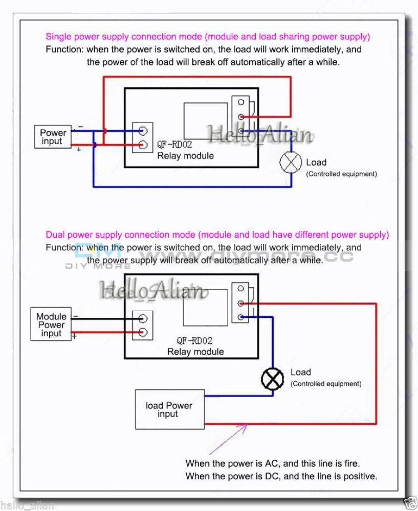
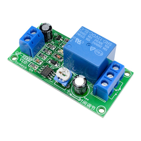 Translation missing: en.products.product.regular_price $4.99{"id":4896534233159,"title":"DC 24V 4 Channel Relay Control Switch RS485\/TTL Anti-reverse Connection Module","handle":"dc-24v-4-channel-relay-control-switch-rs485-ttl-anti-reverse-connection-module","description":"\u003cdiv data-mce-fragment=\"1\"\u003e\u003cspan lang=\"en\" data-mce-fragment=\"1\"\u003e\u003cstrong data-mce-fragment=\"1\"\u003eOverview:\u003c\/strong\u003e\u003c\/span\u003e\u003c\/div\u003e\n\u003cdiv data-mce-fragment=\"1\"\u003e\n\u003cul\u003e\n\u003cli\u003e\u003cspan lang=\"en\" data-mce-fragment=\"1\"\u003eElsay four-way Modbus relay module is equipped with mature and stable 8-bit MCU and RS485 level communication chip. Using standard MODBUS RTU format RS485 communication protocol, it can realize 4 input signal detection and 4 relay output, which can be used for digital detection or power control occasions.\u003c\/span\u003e\u003c\/li\u003e\n\u003c\/ul\u003e\n\u003cspan lang=\"en\" data-mce-fragment=\"1\"\u003e\u003cspan lang=\"en\" data-mce-fragment=\"1\"\u003e\u003cstrong data-mce-fragment=\"1\"\u003eFeatures:\u003c\/strong\u003e\u003cbr data-mce-fragment=\"1\"\u003e\u003c\/span\u003e\u003c\/span\u003e\n\u003cul\u003e\n\u003cli\u003e\u003cspan lang=\"en\" data-mce-fragment=\"1\"\u003eOnboard mature and stable 8bit MCU and MAX485 level conversion chip;\u003c\/span\u003e\u003c\/li\u003e\n\u003cli\u003e\u003cspan lang=\"en\" data-mce-fragment=\"1\"\u003eCommunication protocol: support standard Modbus RTU protocol;\u003c\/span\u003e\u003c\/li\u003e\n\u003cli\u003e\u003cspan lang=\"en\" data-mce-fragment=\"1\"\u003eCommunication interface: support RS485\/TTL UART interface;\u003c\/span\u003e\u003c\/li\u003e\n\u003cli\u003e\u003cspan lang=\"en\" data-mce-fragment=\"1\"\u003eCommunication baud rate: 4800\/9600\/19200, the default is 9600bps, and it supports power-off save;\u003c\/span\u003e\u003c\/li\u003e\n\u003cli\u003e\u003cspan lang=\"en\" data-mce-fragment=\"1\"\u003eOptocoupler input signal range: DC3.3-30V (this input cannot be used for relay control);\u003c\/span\u003e\u003c\/li\u003e\n\u003cli\u003e\u003cspan lang=\"en\" data-mce-fragment=\"1\"\u003eOutput signal: relay switch signal, support manual, flash off, flash off mode, flash off\/flash off delay base is 0.1S, the maximum flash off\/flash off time can be set to 0xFFFF*0.1S=6553.5S;\u003c\/span\u003e\u003c\/li\u003e\n\u003cli\u003e\u003cspan lang=\"en\" data-mce-fragment=\"1\"\u003eDevice address: range 1-255, default 255, support power-off save;\u003c\/span\u003e\u003c\/li\u003e\n\u003cli\u003e\u003cspan lang=\"en\" data-mce-fragment=\"1\"\u003eThe baud rate, input signal, relay status, and device address can be read using software\/commands;\u003c\/span\u003e\u003c\/li\u003e\n\u003cli\u003e\u003cspan lang=\"en\" data-mce-fragment=\"1\"\u003eThere are 4 5V, 10A\/250V AC 10A\/30V DC relays on board, which can be activated continuously for 100,000 times, with diode effusion protection, and short response time;\u003c\/span\u003e\u003c\/li\u003e\n\u003cli\u003e\u003cspan lang=\"en\" data-mce-fragment=\"1\"\u003eOn-board relay switch indicator;\u003c\/span\u003e\u003c\/li\u003e\n\u003cli\u003e\u003cspan lang=\"en\" data-mce-fragment=\"1\"\u003ePower supply voltage: DC7-24V, support DC socket\/5.08mm terminal power supply, with input anti-reverse protection;\u003c\/span\u003e\u003c\/li\u003e\n\u003c\/ul\u003e\n\u003c\/div\u003e\n\u003cdiv data-mce-fragment=\"1\"\u003e\u003cspan data-mce-fragment=\"1\"\u003e\u003cstrong data-mce-fragment=\"1\"\u003e\u003cspan lang=\"en\" data-mce-fragment=\"1\"\u003e\u003cspan title=\"\" data-mce-fragment=\"1\"\u003eHardware introduction and description\u003c\/span\u003e\u003c\/span\u003e\u003c\/strong\u003e\u003c\/span\u003e\u003c\/div\u003e\n\u003cdiv data-mce-fragment=\"1\"\u003e\u003cspan lang=\"en\" data-mce-fragment=\"1\"\u003e\u003cspan title=\"\" data-mce-fragment=\"1\"\u003eBoard size\u003c\/span\u003e\u003c\/span\u003e\u003c\/div\u003e\n\u003cdiv data-mce-fragment=\"1\"\u003e\u003cspan lang=\"en\" data-mce-fragment=\"1\"\u003e\u003cspan title=\"\" data-mce-fragment=\"1\"\u003e\u003cimg src=\"https:\/\/pg-cdn-a2.datacaciques.com\/00\/NDAy\/20\/10\/27\/759miw180130a6g1\/f50580d1c231c450.jpg\" data-mce-fragment=\"1\" data-mce-src=\"https:\/\/pg-cdn-a2.datacaciques.com\/00\/NDAy\/20\/10\/27\/759miw180130a6g1\/f50580d1c231c450.jpg\"\u003e\u003c\/span\u003e\u003c\/span\u003e\u003c\/div\u003e\n\u003cdiv data-mce-fragment=\"1\"\u003e\u003cspan lang=\"en\" data-mce-fragment=\"1\"\u003e\u003cspan title=\"\" data-mce-fragment=\"1\"\u003eInterface introduction\u003c\/span\u003e\u003c\/span\u003e\u003c\/div\u003e\n\u003cdiv data-mce-fragment=\"1\"\u003e\u003cspan lang=\"en\" data-mce-fragment=\"1\"\u003e\u003cspan title=\"\" data-mce-fragment=\"1\"\u003e\u003cimg src=\"https:\/\/pg-cdn-a2.datacaciques.com\/00\/NDAy\/20\/10\/27\/759miw180130a6g1\/4bc7a5d2ad0c45a2.jpg\" data-mce-fragment=\"1\" data-mce-src=\"https:\/\/pg-cdn-a2.datacaciques.com\/00\/NDAy\/20\/10\/27\/759miw180130a6g1\/4bc7a5d2ad0c45a2.jpg\"\u003e\u003c\/span\u003e\u003c\/span\u003e\u003c\/div\u003e\n\u003cdiv data-mce-fragment=\"1\"\u003e\n\u003cul\u003e\n\u003cli\u003e\u003cspan lang=\"en\" data-mce-fragment=\"1\"\u003e\u003cspan title=\"\" data-mce-fragment=\"1\"\u003eDC-005 socket: DC7-24V power input socket;\u003c\/span\u003e\u003c\/span\u003e\u003c\/li\u003e\n\u003cli\u003e\u003cspan lang=\"en\" data-mce-fragment=\"1\"\u003e\u003cspan title=\"\" data-mce-fragment=\"1\"\u003eVCC, GND: DC7-24V 5.08mm power input terminal;\u003c\/span\u003e\u003c\/span\u003e\u003c\/li\u003e\n\u003cli\u003e\u003cspan lang=\"en\" data-mce-fragment=\"1\"\u003e\u003cspan title=\"\" data-mce-fragment=\"1\"\u003eDC3.3-30V optocoupler signal input:\u003c\/span\u003e\u003c\/span\u003e\u003c\/li\u003e\n\u003cli\u003e\u003cspan lang=\"en\" data-mce-fragment=\"1\"\u003e\u003cspan title=\"\" data-mce-fragment=\"1\"\u003eIN1: Channel 1 positive\u003c\/span\u003e\u003c\/span\u003e\u003c\/li\u003e\n\u003cli\u003e\u003cspan lang=\"en\" data-mce-fragment=\"1\"\u003e\u003cspan title=\"\" data-mce-fragment=\"1\"\u003eIN2: Channel 2 positive\u003c\/span\u003e\u003c\/span\u003e\u003c\/li\u003e\n\u003cli\u003e\u003cspan lang=\"en\" data-mce-fragment=\"1\"\u003e\u003cspan title=\"\" data-mce-fragment=\"1\"\u003eIN3: Channel 3 positive\u003c\/span\u003e\u003c\/span\u003e\u003c\/li\u003e\n\u003cli\u003e\u003cspan lang=\"en\" data-mce-fragment=\"1\"\u003e\u003cspan title=\"\" data-mce-fragment=\"1\"\u003eIN4: Channel 4 positive\u003c\/span\u003e\u003c\/span\u003e\u003c\/li\u003e\n\u003cli\u003e\u003cspan lang=\"en\" data-mce-fragment=\"1\"\u003e\u003cspan title=\"\" data-mce-fragment=\"1\"\u003eGND_IN: Common terminal negative\u003c\/span\u003e\u003c\/span\u003e\u003c\/li\u003e\n\u003cli\u003e\u003cspan lang=\"en\" data-mce-fragment=\"1\"\u003e\u003cspan title=\"\" data-mce-fragment=\"1\"\u003eA+, B-: RS485 communication interface, A+, B- are respectively connected to A+, B- of the external control terminal;\u003c\/span\u003e\u003c\/span\u003e\u003c\/li\u003e\n\u003c\/ul\u003e\n\u003cspan lang=\"en\" data-mce-fragment=\"1\"\u003e\u003cspan lang=\"en\" data-mce-fragment=\"1\"\u003e\u003cspan title=\"\" data-mce-fragment=\"1\"\u003e\u003cstrong\u003eRelay switch signal output:\u003c\/strong\u003e\u003cbr data-mce-fragment=\"1\"\u003e\u003c\/span\u003e\u003c\/span\u003e\u003c\/span\u003e\n\u003cul\u003e\n\u003cli\u003e\u003cspan lang=\"en\" data-mce-fragment=\"1\"\u003e\u003cspan title=\"\" data-mce-fragment=\"1\"\u003eNC: Normally closed terminal, the relay is short-connected with COM before it is closed, and it is suspended after it is closed;\u003c\/span\u003e\u003c\/span\u003e\u003c\/li\u003e\n\u003cli\u003e\u003cspan lang=\"en\" data-mce-fragment=\"1\"\u003e\u003cspan title=\"\" data-mce-fragment=\"1\"\u003eCOM: public end;\u003c\/span\u003e\u003c\/span\u003e\u003c\/li\u003e\n\u003cli\u003e\u003cspan lang=\"en\" data-mce-fragment=\"1\"\u003e\u003cspan title=\"\" data-mce-fragment=\"1\"\u003eNO: Normally open end, the relay is suspended before closing, and shorted to COM after closing.\u003c\/span\u003e\u003c\/span\u003e\u003c\/li\u003e\n\u003cli\u003e\u003cspan lang=\"en\" data-mce-fragment=\"1\"\u003e\u003cspan title=\"\" data-mce-fragment=\"1\"\u003e6, GND, RXD, TXD: TTL level UART communication interface, GND, RXD, TXD are respectively connected to GND, TXD, RXD of the external control terminal;\u003c\/span\u003e\u003c\/span\u003e\u003c\/li\u003e\n\u003c\/ul\u003e\n\u003c\/div\u003e\n\u003cdiv data-mce-fragment=\"1\"\u003e\n\u003cspan lang=\"en\" data-mce-fragment=\"1\"\u003e\u003cspan lang=\"en\" data-mce-fragment=\"1\"\u003e\u003cspan title=\"\" data-mce-fragment=\"1\"\u003e\u003cstrong data-mce-fragment=\"1\"\u003eProduct Parameters:\u003c\/strong\u003e\u003cbr data-mce-fragment=\"1\"\u003e\u003c\/span\u003e\u003c\/span\u003e\u003c\/span\u003e\n\u003cul\u003e\n\u003cli\u003e\u003cspan lang=\"en\" data-mce-fragment=\"1\"\u003e\u003cspan title=\"\" data-mce-fragment=\"1\"\u003eItem name: 4CH Modbus Relay Module \u003c\/span\u003e\u003c\/span\u003e\u003c\/li\u003e\n\u003cli\u003e\u003cspan lang=\"en\" data-mce-fragment=\"1\"\u003e\u003cspan title=\"\" data-mce-fragment=\"1\"\u003eWork voltage:DC 7V~24V\u003c\/span\u003e\u003c\/span\u003e\u003c\/li\u003e\n\u003cli\u003e\u003cspan lang=\"en\" data-mce-fragment=\"1\"\u003e\u003cspan title=\"\" data-mce-fragment=\"1\"\u003eBaud rate:4800\/9600\/19600bps(default 9600bps)\u003c\/span\u003e\u003c\/span\u003e\u003c\/li\u003e\n\u003cli\u003e\u003cspan lang=\"en\" data-mce-fragment=\"1\"\u003e\u003cspan title=\"\" data-mce-fragment=\"1\"\u003eOptocoupler input signal:DC 3.3V~30V\u003c\/span\u003e\u003c\/span\u003e\u003c\/li\u003e\n\u003cli\u003e\u003cspan lang=\"en\" data-mce-fragment=\"1\"\u003e\u003cspan title=\"\" data-mce-fragment=\"1\"\u003eSet address:1~255\u003c\/span\u003e\u003c\/span\u003e\u003c\/li\u003e\n\u003cli\u003e\u003cspan lang=\"en\" data-mce-fragment=\"1\"\u003e\u003cspan title=\"\" data-mce-fragment=\"1\"\u003eRelay contorl mode: ON\/OFF,Delay_ON,Delay_OFF mode\u003c\/span\u003e\u003c\/span\u003e\u003c\/li\u003e\n\u003cli\u003e\u003cspan lang=\"en\" data-mce-fragment=\"1\"\u003e\u003cspan title=\"\" data-mce-fragment=\"1\"\u003eDelay time: 0~6553.5s \u003c\/span\u003e\u003c\/span\u003e\u003c\/li\u003e\n\u003cli\u003e\u003cspan lang=\"en\" data-mce-fragment=\"1\"\u003e\u003cspan title=\"\" data-mce-fragment=\"1\"\u003eLoad: AC 250V 10A or DC 28V 10A\u003c\/span\u003e\u003c\/span\u003e\u003c\/li\u003e\n\u003cli\u003e\u003cspan lang=\"en\" data-mce-fragment=\"1\"\u003e\u003cspan title=\"\" data-mce-fragment=\"1\"\u003eProtocol:Modbus RTU\u003c\/span\u003e\u003c\/span\u003e\u003c\/li\u003e\n\u003cli\u003e\u003cspan lang=\"en\" data-mce-fragment=\"1\"\u003e\u003cspan title=\"\" data-mce-fragment=\"1\"\u003eInterface:RS485\/TTL UART\u003c\/span\u003e\u003c\/span\u003e\u003c\/li\u003e\n\u003cli\u003e\u003cspan lang=\"en\" data-mce-fragment=\"1\"\u003e\u003cspan title=\"\" data-mce-fragment=\"1\"\u003eControl channel: 4channel\u003c\/span\u003e\u003c\/span\u003e\u003c\/li\u003e\n\u003cli\u003e\u003cspan lang=\"en\" data-mce-fragment=\"1\"\u003e\u003cspan title=\"\" data-mce-fragment=\"1\"\u003eOperating Temperature:-20℃~85℃\u003c\/span\u003e\u003c\/span\u003e\u003c\/li\u003e\n\u003cli\u003e\u003cspan lang=\"en\" data-mce-fragment=\"1\"\u003e\u003cspan title=\"\" data-mce-fragment=\"1\"\u003eOperating Humidity:5%~95%RH\u003c\/span\u003e\u003c\/span\u003e\u003c\/li\u003e\n\u003cli\u003e\u003cspan lang=\"en\" data-mce-fragment=\"1\"\u003e\u003cspan title=\"\" data-mce-fragment=\"1\"\u003eModule Size:93*90*20mm\u003c\/span\u003e\u003c\/span\u003e\u003c\/li\u003e\n\u003c\/ul\u003e\n\u003cspan lang=\"en\" data-mce-fragment=\"1\"\u003e\u003cspan lang=\"en\" data-mce-fragment=\"1\"\u003e\u003cspan title=\"\" data-mce-fragment=\"1\"\u003e\u003cimg src=\"https:\/\/pg-cdn-a2.datacaciques.com\/00\/NDAy\/20\/10\/27\/759miw180130a6g1\/5a40dd1349231871.jpg\" data-mce-fragment=\"1\" data-mce-src=\"https:\/\/pg-cdn-a2.datacaciques.com\/00\/NDAy\/20\/10\/27\/759miw180130a6g1\/5a40dd1349231871.jpg\"\u003e\u003cbr data-mce-fragment=\"1\"\u003e\u003cstrong data-mce-fragment=\"1\"\u003eModbus RTU Command:\u003c\/strong\u003e\u003cbr data-mce-fragment=\"1\"\u003e\u003c\/span\u003e\u003c\/span\u003e\u003c\/span\u003e\n\u003cul\u003e\n\u003cli\u003e\u003cspan lang=\"en\" data-mce-fragment=\"1\"\u003e\u003cspan title=\"\" data-mce-fragment=\"1\"\u003eSuppose the device address is 0xFF so return 00 10 00 00 00 01 02 00 FF EB 80 and the 9th btye is device address.\u003c\/span\u003e\u003c\/span\u003e\u003c\/li\u003e\n\u003cli\u003e\u003cspan lang=\"en\" data-mce-fragment=\"1\"\u003e\u003cspan title=\"\" data-mce-fragment=\"1\"\u003eTurn ON CH_1 Relay(Normal Mode):\u003c\/span\u003e\u003c\/span\u003e\u003c\/li\u003e\n\u003cli\u003e\u003cspan lang=\"en\" data-mce-fragment=\"1\"\u003e\u003cspan title=\"\" data-mce-fragment=\"1\"\u003e Send: FF 05 00 00 FF 00 99 E4\u003c\/span\u003e\u003c\/span\u003e\u003c\/li\u003e\n\u003cli\u003e\u003cspan lang=\"en\" data-mce-fragment=\"1\"\u003e\u003cspan title=\"\" data-mce-fragment=\"1\"\u003e Return: FF 05 00 00 FF 00 99 E4\u003c\/span\u003e\u003c\/span\u003e\u003c\/li\u003e\n\u003cli\u003e\u003cspan lang=\"en\" data-mce-fragment=\"1\"\u003e\u003cspan title=\"\" data-mce-fragment=\"1\"\u003e Note_1:The 3rd and 4th byte are relay addresses.So it can be 0x0000,0x0001,0x0002,0x0003.\u003c\/span\u003e\u003c\/span\u003e\u003c\/li\u003e\n\u003cli\u003e\u003cspan lang=\"en\" data-mce-fragment=\"1\"\u003e\u003cspan title=\"\" data-mce-fragment=\"1\"\u003e Note_2:The 5th and 6th byte are relay data.0xFF00 means turn ON relay and 0x0000 means turn OFF relay.\u003c\/span\u003e\u003c\/span\u003e\u003c\/li\u003e\n\u003cli\u003e\u003cspan lang=\"en\" data-mce-fragment=\"1\"\u003e\u003cspan title=\"\" data-mce-fragment=\"1\"\u003eTurn OFF CH_1 Relay(Normal Mode):\u003c\/span\u003e\u003c\/span\u003e\u003c\/li\u003e\n\u003cli\u003e\u003cspan lang=\"en\" data-mce-fragment=\"1\"\u003e\u003cspan title=\"\" data-mce-fragment=\"1\"\u003e Send: FF 05 00 00 00 00 D8 14\u003c\/span\u003e\u003c\/span\u003e\u003c\/li\u003e\n\u003cli\u003e\u003cspan lang=\"en\" data-mce-fragment=\"1\"\u003e\u003cspan title=\"\" data-mce-fragment=\"1\"\u003e Return: FF 05 00 00 00 00 D8 14\u003c\/span\u003e\u003c\/span\u003e\u003c\/li\u003e\n\u003cli\u003e\u003cspan lang=\"en\" data-mce-fragment=\"1\"\u003e\u003cspan title=\"\" data-mce-fragment=\"1\"\u003eTurn ON CH_2 Relay(Normal Mode):\u003c\/span\u003e\u003c\/span\u003e\u003c\/li\u003e\n\u003cli\u003e\u003cspan lang=\"en\" data-mce-fragment=\"1\"\u003e\u003cspan title=\"\" data-mce-fragment=\"1\"\u003e Send: FF 05 00 01 FF 00 C8 24\u003c\/span\u003e\u003c\/span\u003e\u003c\/li\u003e\n\u003cli\u003e\u003cspan lang=\"en\" data-mce-fragment=\"1\"\u003e\u003cspan title=\"\" data-mce-fragment=\"1\"\u003e Return: FF 05 00 01 FF 00 C8 24\u003c\/span\u003e\u003c\/span\u003e\u003c\/li\u003e\n\u003cli\u003e\u003cspan lang=\"en\" data-mce-fragment=\"1\"\u003e\u003cspan title=\"\" data-mce-fragment=\"1\"\u003eTurn OFF CH_2 Relay(Normal Mode):\u003c\/span\u003e\u003c\/span\u003e\u003c\/li\u003e\n\u003cli\u003e\u003cspan lang=\"en\" data-mce-fragment=\"1\"\u003e\u003cspan title=\"\" data-mce-fragment=\"1\"\u003e Send: FF 05 00 01 00 00 89 D4\u003c\/span\u003e\u003c\/span\u003e\u003c\/li\u003e\n\u003cli\u003e\u003cspan lang=\"en\" data-mce-fragment=\"1\"\u003e\u003cspan title=\"\" data-mce-fragment=\"1\"\u003e Return: FF 05 00 01 00 00 89 D4\u003c\/span\u003e\u003c\/span\u003e\u003c\/li\u003e\n\u003cli\u003e\u003cspan lang=\"en\" data-mce-fragment=\"1\"\u003e\u003cspan title=\"\" data-mce-fragment=\"1\"\u003eTurn ON All relays:\u003c\/span\u003e\u003c\/span\u003e\u003c\/li\u003e\n\u003cli\u003e\u003cspan lang=\"en\" data-mce-fragment=\"1\"\u003e\u003cspan title=\"\" data-mce-fragment=\"1\"\u003e Send: FF 0F 00 00 00 08 01 FF 30 1D\u003c\/span\u003e\u003c\/span\u003e\u003c\/li\u003e\n\u003cli\u003e\u003cspan lang=\"en\" data-mce-fragment=\"1\"\u003e\u003cspan title=\"\" data-mce-fragment=\"1\"\u003e Return: FF 0F 00 00 00 08 41 D3\u003c\/span\u003e\u003c\/span\u003e\u003c\/li\u003e\n\u003cli\u003e\u003cspan lang=\"en\" data-mce-fragment=\"1\"\u003e\u003cspan title=\"\" data-mce-fragment=\"1\"\u003eTurn OFF All relays:\u003c\/span\u003e\u003c\/span\u003e\u003c\/li\u003e\n\u003cli\u003e\u003cspan lang=\"en\" data-mce-fragment=\"1\"\u003e\u003cspan title=\"\" data-mce-fragment=\"1\"\u003e Send: FF 0F 00 00 00 08 01 00 70 5D\u003c\/span\u003e\u003c\/span\u003e\u003c\/li\u003e\n\u003cli\u003e\u003cspan lang=\"en\" data-mce-fragment=\"1\"\u003e\u003cspan title=\"\" data-mce-fragment=\"1\"\u003e Return: FF 0F 00 00 00 08 41 D3\u003c\/span\u003e\u003c\/span\u003e\u003c\/li\u003e\n\u003cli\u003e\u003cspan lang=\"en\" data-mce-fragment=\"1\"\u003e\u003cspan title=\"\" data-mce-fragment=\"1\"\u003eSet device address to 0x01:\u003c\/span\u003e\u003c\/span\u003e\u003c\/li\u003e\n\u003cli\u003e\u003cspan lang=\"en\" data-mce-fragment=\"1\"\u003e\u003cspan title=\"\" data-mce-fragment=\"1\"\u003e Send: 00 10 00 00 00 01 02 00 01 6A 00\u003c\/span\u003e\u003c\/span\u003e\u003c\/li\u003e\n\u003cli\u003e\u003cspan lang=\"en\" data-mce-fragment=\"1\"\u003e\u003cspan title=\"\" data-mce-fragment=\"1\"\u003e Return: 00 10 00 00 00 01 02 00 01 6A 00\u003c\/span\u003e\u003c\/span\u003e\u003c\/li\u003e\n\u003cli\u003e\u003cspan lang=\"en\" data-mce-fragment=\"1\"\u003e\u003cspan title=\"\" data-mce-fragment=\"1\"\u003e Note: The 9th btye is device address.\u003c\/span\u003e\u003c\/span\u003e\u003c\/li\u003e\n\u003cli\u003e\u003cspan lang=\"en\" data-mce-fragment=\"1\"\u003e\u003cspan title=\"\" data-mce-fragment=\"1\"\u003eSet device address to 0xFF:\u003c\/span\u003e\u003c\/span\u003e\u003c\/li\u003e\n\u003cli\u003e\u003cspan lang=\"en\" data-mce-fragment=\"1\"\u003e\u003cspan title=\"\" data-mce-fragment=\"1\"\u003e Send: 00 10 00 00 00 01 02 00 FF EB 80\u003c\/span\u003e\u003c\/span\u003e\u003c\/li\u003e\n\u003cli\u003e\u003cspan lang=\"en\" data-mce-fragment=\"1\"\u003e\u003cspan title=\"\" data-mce-fragment=\"1\"\u003e Return: 00 10 00 00 00 01 02 00 FF EB 80\u003c\/span\u003e\u003c\/span\u003e\u003c\/li\u003e\n\u003cli\u003e\u003cspan lang=\"en\" data-mce-fragment=\"1\"\u003e\u003cspan title=\"\" data-mce-fragment=\"1\"\u003eRead device address:\u003c\/span\u003e\u003c\/span\u003e\u003c\/li\u003e\n\u003cli\u003e\u003cspan lang=\"en\" data-mce-fragment=\"1\"\u003e\u003cspan title=\"\" data-mce-fragment=\"1\"\u003e Send: 00 03 00 00 00 01 85 DB\u003c\/span\u003e\u003c\/span\u003e\u003c\/li\u003e\n\u003cli\u003e\u003cspan lang=\"en\" data-mce-fragment=\"1\"\u003e\u003cspan title=\"\" data-mce-fragment=\"1\"\u003e Return: 00 03 02 00 FF C5 C4\u003c\/span\u003e\u003c\/span\u003e\u003c\/li\u003e\n\u003cli\u003e\u003cspan lang=\"en\" data-mce-fragment=\"1\"\u003e\u003cspan title=\"\" data-mce-fragment=\"1\"\u003e Note: The 5th btye is device address.\u003c\/span\u003e\u003c\/span\u003e\u003c\/li\u003e\n\u003cli\u003e\u003cspan lang=\"en\" data-mce-fragment=\"1\"\u003e\u003cspan title=\"\" data-mce-fragment=\"1\"\u003eRead relay status:\u003c\/span\u003e\u003c\/span\u003e\u003c\/li\u003e\n\u003cli\u003e\u003cspan lang=\"en\" data-mce-fragment=\"1\"\u003e\u003cspan title=\"\" data-mce-fragment=\"1\"\u003e Send: FF 01 00 00 00 08 28 12\u003c\/span\u003e\u003c\/span\u003e\u003c\/li\u003e\n\u003cli\u003e\u003cspan lang=\"en\" data-mce-fragment=\"1\"\u003e\u003cspan title=\"\" data-mce-fragment=\"1\"\u003e Return: FF 01 01 01 A1 A0\u003c\/span\u003e\u003c\/span\u003e\u003c\/li\u003e\n\u003cli\u003e\u003cspan lang=\"en\" data-mce-fragment=\"1\"\u003e\u003cspan title=\"\" data-mce-fragment=\"1\"\u003e Note:The 4th means which one relay.0 means OFF and 1 means ON.\u003c\/span\u003e\u003c\/span\u003e\u003c\/li\u003e\n\u003cli\u003e\u003cspan lang=\"en\" data-mce-fragment=\"1\"\u003e\u003cspan title=\"\" data-mce-fragment=\"1\"\u003eRead optocoupler input staturs:\u003c\/span\u003e\u003c\/span\u003e\u003c\/li\u003e\n\u003cli\u003e\u003cspan lang=\"en\" data-mce-fragment=\"1\"\u003e\u003cspan title=\"\" data-mce-fragment=\"1\"\u003e Send: FF 02 00 00 00 08 6C 12\u003c\/span\u003e\u003c\/span\u003e\u003c\/li\u003e\n\u003cli\u003e\u003cspan lang=\"en\" data-mce-fragment=\"1\"\u003e\u003cspan title=\"\" data-mce-fragment=\"1\"\u003e Return: FF 02 01 01 51 A0\u003c\/span\u003e\u003c\/span\u003e\u003c\/li\u003e\n\u003cli\u003e\u003cspan lang=\"en\" data-mce-fragment=\"1\"\u003e\u003cspan title=\"\" data-mce-fragment=\"1\"\u003e Note:The 4th means which one input.0 means low level signal input and 1 means high level signal input.\u003c\/span\u003e\u003c\/span\u003e\u003c\/li\u003e\n\u003cli\u003e\u003cspan lang=\"en\" data-mce-fragment=\"1\"\u003e\u003cspan title=\"\" data-mce-fragment=\"1\"\u003eSet baud rate 4800bps:\u003c\/span\u003e\u003c\/span\u003e\u003c\/li\u003e\n\u003cli\u003e\u003cspan lang=\"en\" data-mce-fragment=\"1\"\u003e\u003cspan title=\"\" data-mce-fragment=\"1\"\u003e Send: FF 10 03 E9 00 01 02 00 02 4A 0C\u003c\/span\u003e\u003c\/span\u003e\u003c\/li\u003e\n\u003cli\u003e\u003cspan lang=\"en\" data-mce-fragment=\"1\"\u003e\u003cspan title=\"\" data-mce-fragment=\"1\"\u003e Return: FF 10 03 E9 00 01 C5 A7\u003c\/span\u003e\u003c\/span\u003e\u003c\/li\u003e\n\u003cli\u003e\u003cspan lang=\"en\" data-mce-fragment=\"1\"\u003e\u003cspan title=\"\" data-mce-fragment=\"1\"\u003e Note:The 9th btye is baud rate value.0x02 is 4800bps.0x03 is 9600bps.0x04 is 19200bps.\u003c\/span\u003e\u003c\/span\u003e\u003c\/li\u003e\n\u003cli\u003e\u003cspan lang=\"en\" data-mce-fragment=\"1\"\u003e\u003cspan title=\"\" data-mce-fragment=\"1\"\u003eSet baud rate 9600bps:\u003c\/span\u003e\u003c\/span\u003e\u003c\/li\u003e\n\u003cli\u003e\u003cspan lang=\"en\" data-mce-fragment=\"1\"\u003e\u003cspan title=\"\" data-mce-fragment=\"1\"\u003e Send: FF 10 03 E9 00 01 02 00 03 8B CC\u003c\/span\u003e\u003c\/span\u003e\u003c\/li\u003e\n\u003cli\u003e\u003cspan lang=\"en\" data-mce-fragment=\"1\"\u003e\u003cspan title=\"\" data-mce-fragment=\"1\"\u003e Return: FF 10 03 E9 00 01 C5 A7\u003c\/span\u003e\u003c\/span\u003e\u003c\/li\u003e\n\u003cli\u003e\u003cspan lang=\"en\" data-mce-fragment=\"1\"\u003e\u003cspan title=\"\" data-mce-fragment=\"1\"\u003eSet baud rate 19200bps:\u003c\/span\u003e\u003c\/span\u003e\u003c\/li\u003e\n\u003cli\u003e\u003cspan lang=\"en\" data-mce-fragment=\"1\"\u003e\u003cspan title=\"\" data-mce-fragment=\"1\"\u003e Send: FF 10 03 E9 00 01 02 00 04 CA 0E\u003c\/span\u003e\u003c\/span\u003e\u003c\/li\u003e\n\u003cli\u003e\u003cspan lang=\"en\" data-mce-fragment=\"1\"\u003e\u003cspan title=\"\" data-mce-fragment=\"1\"\u003e Return: FF 10 03 E9 00 01 C5 A7\u003c\/span\u003e\u003c\/span\u003e\u003c\/li\u003e\n\u003cli\u003e\u003cspan lang=\"en\" data-mce-fragment=\"1\"\u003e\u003cspan title=\"\" data-mce-fragment=\"1\"\u003eTurn ON CH_1 Relay(2S Flashing Mode):\u003c\/span\u003e\u003c\/span\u003e\u003c\/li\u003e\n\u003cli\u003e\u003cspan lang=\"en\" data-mce-fragment=\"1\"\u003e\u003cspan title=\"\" data-mce-fragment=\"1\"\u003e Send: FF 10 00 03 00 02 04 00 04 00 14 C5 9F\u003c\/span\u003e\u003c\/span\u003e\u003c\/li\u003e\n\u003cli\u003e\u003cspan lang=\"en\" data-mce-fragment=\"1\"\u003e\u003cspan title=\"\" data-mce-fragment=\"1\"\u003e Return: FF 10 00 03 00 02 A4 16\u003c\/span\u003e\u003c\/span\u003e\u003c\/li\u003e\n\u003cli\u003e\u003cspan lang=\"en\" data-mce-fragment=\"1\"\u003e\u003cspan title=\"\" data-mce-fragment=\"1\"\u003e Note_1:The 3rd and 4th byte are relay addresses.So CH1~CH4 can be 0x0003,0x0008,0x000D,0x0012.\u003c\/span\u003e\u003c\/span\u003e\u003c\/li\u003e\n\u003cli\u003e\u003cspan lang=\"en\" data-mce-fragment=\"1\"\u003e\u003cspan title=\"\" data-mce-fragment=\"1\"\u003e Note_2:The 10th and 11th byte are delay time in second.The minimum delay time is 0.1s.Relay will OFF after delay time.So the delay time in this command is : 0x0014*0.1=2S.\u003c\/span\u003e\u003c\/span\u003e\u003c\/li\u003e\n\u003cli\u003e\u003cspan lang=\"en\" data-mce-fragment=\"1\"\u003e\u003cspan title=\"\" data-mce-fragment=\"1\"\u003eTurn OFF CH_1 Relay(3S Flashing Mode):\u003c\/span\u003e\u003c\/span\u003e\u003c\/li\u003e\n\u003cli\u003e\u003cspan lang=\"en\" data-mce-fragment=\"1\"\u003e\u003cspan title=\"\" data-mce-fragment=\"1\"\u003e Send: FF 10 00 03 00 02 04 00 02 00 1E A5 99\u003c\/span\u003e\u003c\/span\u003e\u003c\/li\u003e\n\u003cli\u003e\u003cspan lang=\"en\" data-mce-fragment=\"1\"\u003e\u003cspan title=\"\" data-mce-fragment=\"1\"\u003e Return: FF 10 00 03 00 02 A4 16\u003c\/span\u003e\u003c\/span\u003e\u003c\/li\u003e\n\u003cli\u003e\u003cspan lang=\"en\" data-mce-fragment=\"1\"\u003e\u003cspan title=\"\" data-mce-fragment=\"1\"\u003e Note:Relay will ON after delay time.So the delay time in this command is : 0x001E*0.1=3S.\u003c\/span\u003e\u003c\/span\u003e\u003c\/li\u003e\n\u003c\/ul\u003e\n\u003cspan lang=\"en\" data-mce-fragment=\"1\"\u003e\u003cspan lang=\"en\" data-mce-fragment=\"1\"\u003e\u003cspan title=\"\" data-mce-fragment=\"1\"\u003e\u003cimg src=\"https:\/\/pg-cdn-a2.datacaciques.com\/00\/NDAy\/20\/10\/27\/759miw180130a6g1\/b4e1c2017abb1ec6.jpg\" data-mce-fragment=\"1\" data-mce-src=\"https:\/\/pg-cdn-a2.datacaciques.com\/00\/NDAy\/20\/10\/27\/759miw180130a6g1\/b4e1c2017abb1ec6.jpg\"\u003e\u003cbr data-mce-fragment=\"1\"\u003e\u003cstrong data-mce-fragment=\"1\"\u003ePackage Include:\u003c\/strong\u003e\u003cbr data-mce-fragment=\"1\"\u003e\u003c\/span\u003e\u003c\/span\u003e\u003c\/span\u003e\n\u003cul\u003e\n\u003cli\u003e\u003cspan lang=\"en\" data-mce-fragment=\"1\"\u003e\u003cspan title=\"\" data-mce-fragment=\"1\"\u003e 1PC 4CH Modbus Relay Module \u003c\/span\u003e\u003c\/span\u003e\u003c\/li\u003e\n\u003c\/ul\u003e\n\u003c\/div\u003e\n\u003cdiv data-mce-fragment=\"1\"\u003e\u003cspan lang=\"en\" data-mce-fragment=\"1\"\u003e\u003cspan title=\"\" data-mce-fragment=\"1\"\u003e \u003c\/span\u003e\u003c\/span\u003e\u003c\/div\u003e","published_at":"2020-10-29T16:43:18+08:00","created_at":"2020-10-28T12:04:09+08:00","vendor":"DIYMORE","type":"","tags":[],"price":1099,"price_min":1099,"price_max":1099,"available":true,"price_varies":false,"compare_at_price":null,"compare_at_price_min":0,"compare_at_price_max":0,"compare_at_price_varies":false,"variants":[{"id":32644275765319,"title":"Default Title","option1":"Default Title","option2":null,"option3":null,"sku":"XM0006","requires_shipping":true,"taxable":false,"featured_image":null,"available":true,"name":"DC 24V 4 Channel Relay Control Switch RS485\/TTL Anti-reverse Connection Module","public_title":null,"options":["Default Title"],"price":1099,"weight":0,"compare_at_price":null,"inventory_management":"shopify","barcode":"","requires_selling_plan":false,"selling_plan_allocations":[],"quantity_rule":{"min":1,"max":null,"increment":1}}],"images":["\/\/www.diymore.cc\/cdn\/shop\/products\/3_c1c2716b-4e56-4778-96d4-eb4ff9c7620a.jpg?v=1603857853","\/\/www.diymore.cc\/cdn\/shop\/products\/5_ff208254-a902-4d04-93e4-bce5ea8eb512.jpg?v=1603857854","\/\/www.diymore.cc\/cdn\/shop\/products\/4_0b281e6a-ef90-4366-8a24-d9a167cf31ca.jpg?v=1603857854","\/\/www.diymore.cc\/cdn\/shop\/products\/1_968bb946-a0f2-4ed7-8618-2ab8b7fa26f9.jpg?v=1603857854","\/\/www.diymore.cc\/cdn\/shop\/products\/2_5f6abbf8-5697-4e69-9c60-03559cfb6029.jpg?v=1603857854"],"featured_image":"\/\/www.diymore.cc\/cdn\/shop\/products\/3_c1c2716b-4e56-4778-96d4-eb4ff9c7620a.jpg?v=1603857853","options":["Title"],"media":[{"alt":null,"id":7652174987335,"position":1,"preview_image":{"aspect_ratio":1.0,"height":1000,"width":1000,"src":"\/\/www.diymore.cc\/cdn\/shop\/products\/3_c1c2716b-4e56-4778-96d4-eb4ff9c7620a.jpg?v=1603857853"},"aspect_ratio":1.0,"height":1000,"media_type":"image","src":"\/\/www.diymore.cc\/cdn\/shop\/products\/3_c1c2716b-4e56-4778-96d4-eb4ff9c7620a.jpg?v=1603857853","width":1000},{"alt":null,"id":7652175020103,"position":2,"preview_image":{"aspect_ratio":1.0,"height":1000,"width":1000,"src":"\/\/www.diymore.cc\/cdn\/shop\/products\/5_ff208254-a902-4d04-93e4-bce5ea8eb512.jpg?v=1603857854"},"aspect_ratio":1.0,"height":1000,"media_type":"image","src":"\/\/www.diymore.cc\/cdn\/shop\/products\/5_ff208254-a902-4d04-93e4-bce5ea8eb512.jpg?v=1603857854","width":1000},{"alt":null,"id":7652175052871,"position":3,"preview_image":{"aspect_ratio":1.0,"height":1000,"width":1000,"src":"\/\/www.diymore.cc\/cdn\/shop\/products\/4_0b281e6a-ef90-4366-8a24-d9a167cf31ca.jpg?v=1603857854"},"aspect_ratio":1.0,"height":1000,"media_type":"image","src":"\/\/www.diymore.cc\/cdn\/shop\/products\/4_0b281e6a-ef90-4366-8a24-d9a167cf31ca.jpg?v=1603857854","width":1000},{"alt":null,"id":7652175085639,"position":4,"preview_image":{"aspect_ratio":1.0,"height":1000,"width":1000,"src":"\/\/www.diymore.cc\/cdn\/shop\/products\/1_968bb946-a0f2-4ed7-8618-2ab8b7fa26f9.jpg?v=1603857854"},"aspect_ratio":1.0,"height":1000,"media_type":"image","src":"\/\/www.diymore.cc\/cdn\/shop\/products\/1_968bb946-a0f2-4ed7-8618-2ab8b7fa26f9.jpg?v=1603857854","width":1000},{"alt":null,"id":7652175118407,"position":5,"preview_image":{"aspect_ratio":1.0,"height":1000,"width":1000,"src":"\/\/www.diymore.cc\/cdn\/shop\/products\/2_5f6abbf8-5697-4e69-9c60-03559cfb6029.jpg?v=1603857854"},"aspect_ratio":1.0,"height":1000,"media_type":"image","src":"\/\/www.diymore.cc\/cdn\/shop\/products\/2_5f6abbf8-5697-4e69-9c60-03559cfb6029.jpg?v=1603857854","width":1000}],"requires_selling_plan":false,"selling_plan_groups":[],"content":"\u003cdiv data-mce-fragment=\"1\"\u003e\u003cspan lang=\"en\" data-mce-fragment=\"1\"\u003e\u003cstrong data-mce-fragment=\"1\"\u003eOverview:\u003c\/strong\u003e\u003c\/span\u003e\u003c\/div\u003e\n\u003cdiv data-mce-fragment=\"1\"\u003e\n\u003cul\u003e\n\u003cli\u003e\u003cspan lang=\"en\" data-mce-fragment=\"1\"\u003eElsay four-way Modbus relay module is equipped with mature and stable 8-bit MCU and RS485 level communication chip. Using standard MODBUS RTU format RS485 communication protocol, it can realize 4 input signal detection and 4 relay output, which can be used for digital detection or power control occasions.\u003c\/span\u003e\u003c\/li\u003e\n\u003c\/ul\u003e\n\u003cspan lang=\"en\" data-mce-fragment=\"1\"\u003e\u003cspan lang=\"en\" data-mce-fragment=\"1\"\u003e\u003cstrong data-mce-fragment=\"1\"\u003eFeatures:\u003c\/strong\u003e\u003cbr data-mce-fragment=\"1\"\u003e\u003c\/span\u003e\u003c\/span\u003e\n\u003cul\u003e\n\u003cli\u003e\u003cspan lang=\"en\" data-mce-fragment=\"1\"\u003eOnboard mature and stable 8bit MCU and MAX485 level conversion chip;\u003c\/span\u003e\u003c\/li\u003e\n\u003cli\u003e\u003cspan lang=\"en\" data-mce-fragment=\"1\"\u003eCommunication protocol: support standard Modbus RTU protocol;\u003c\/span\u003e\u003c\/li\u003e\n\u003cli\u003e\u003cspan lang=\"en\" data-mce-fragment=\"1\"\u003eCommunication interface: support RS485\/TTL UART interface;\u003c\/span\u003e\u003c\/li\u003e\n\u003cli\u003e\u003cspan lang=\"en\" data-mce-fragment=\"1\"\u003eCommunication baud rate: 4800\/9600\/19200, the default is 9600bps, and it supports power-off save;\u003c\/span\u003e\u003c\/li\u003e\n\u003cli\u003e\u003cspan lang=\"en\" data-mce-fragment=\"1\"\u003eOptocoupler input signal range: DC3.3-30V (this input cannot be used for relay control);\u003c\/span\u003e\u003c\/li\u003e\n\u003cli\u003e\u003cspan lang=\"en\" data-mce-fragment=\"1\"\u003eOutput signal: relay switch signal, support manual, flash off, flash off mode, flash off\/flash off delay base is 0.1S, the maximum flash off\/flash off time can be set to 0xFFFF*0.1S=6553.5S;\u003c\/span\u003e\u003c\/li\u003e\n\u003cli\u003e\u003cspan lang=\"en\" data-mce-fragment=\"1\"\u003eDevice address: range 1-255, default 255, support power-off save;\u003c\/span\u003e\u003c\/li\u003e\n\u003cli\u003e\u003cspan lang=\"en\" data-mce-fragment=\"1\"\u003eThe baud rate, input signal, relay status, and device address can be read using software\/commands;\u003c\/span\u003e\u003c\/li\u003e\n\u003cli\u003e\u003cspan lang=\"en\" data-mce-fragment=\"1\"\u003eThere are 4 5V, 10A\/250V AC 10A\/30V DC relays on board, which can be activated continuously for 100,000 times, with diode effusion protection, and short response time;\u003c\/span\u003e\u003c\/li\u003e\n\u003cli\u003e\u003cspan lang=\"en\" data-mce-fragment=\"1\"\u003eOn-board relay switch indicator;\u003c\/span\u003e\u003c\/li\u003e\n\u003cli\u003e\u003cspan lang=\"en\" data-mce-fragment=\"1\"\u003ePower supply voltage: DC7-24V, support DC socket\/5.08mm terminal power supply, with input anti-reverse protection;\u003c\/span\u003e\u003c\/li\u003e\n\u003c\/ul\u003e\n\u003c\/div\u003e\n\u003cdiv data-mce-fragment=\"1\"\u003e\u003cspan data-mce-fragment=\"1\"\u003e\u003cstrong data-mce-fragment=\"1\"\u003e\u003cspan lang=\"en\" data-mce-fragment=\"1\"\u003e\u003cspan title=\"\" data-mce-fragment=\"1\"\u003eHardware introduction and description\u003c\/span\u003e\u003c\/span\u003e\u003c\/strong\u003e\u003c\/span\u003e\u003c\/div\u003e\n\u003cdiv data-mce-fragment=\"1\"\u003e\u003cspan lang=\"en\" data-mce-fragment=\"1\"\u003e\u003cspan title=\"\" data-mce-fragment=\"1\"\u003eBoard size\u003c\/span\u003e\u003c\/span\u003e\u003c\/div\u003e\n\u003cdiv data-mce-fragment=\"1\"\u003e\u003cspan lang=\"en\" data-mce-fragment=\"1\"\u003e\u003cspan title=\"\" data-mce-fragment=\"1\"\u003e\u003cimg src=\"https:\/\/pg-cdn-a2.datacaciques.com\/00\/NDAy\/20\/10\/27\/759miw180130a6g1\/f50580d1c231c450.jpg\" data-mce-fragment=\"1\" data-mce-src=\"https:\/\/pg-cdn-a2.datacaciques.com\/00\/NDAy\/20\/10\/27\/759miw180130a6g1\/f50580d1c231c450.jpg\"\u003e\u003c\/span\u003e\u003c\/span\u003e\u003c\/div\u003e\n\u003cdiv data-mce-fragment=\"1\"\u003e\u003cspan lang=\"en\" data-mce-fragment=\"1\"\u003e\u003cspan title=\"\" data-mce-fragment=\"1\"\u003eInterface introduction\u003c\/span\u003e\u003c\/span\u003e\u003c\/div\u003e\n\u003cdiv data-mce-fragment=\"1\"\u003e\u003cspan lang=\"en\" data-mce-fragment=\"1\"\u003e\u003cspan title=\"\" data-mce-fragment=\"1\"\u003e\u003cimg src=\"https:\/\/pg-cdn-a2.datacaciques.com\/00\/NDAy\/20\/10\/27\/759miw180130a6g1\/4bc7a5d2ad0c45a2.jpg\" data-mce-fragment=\"1\" data-mce-src=\"https:\/\/pg-cdn-a2.datacaciques.com\/00\/NDAy\/20\/10\/27\/759miw180130a6g1\/4bc7a5d2ad0c45a2.jpg\"\u003e\u003c\/span\u003e\u003c\/span\u003e\u003c\/div\u003e\n\u003cdiv data-mce-fragment=\"1\"\u003e\n\u003cul\u003e\n\u003cli\u003e\u003cspan lang=\"en\" data-mce-fragment=\"1\"\u003e\u003cspan title=\"\" data-mce-fragment=\"1\"\u003eDC-005 socket: DC7-24V power input socket;\u003c\/span\u003e\u003c\/span\u003e\u003c\/li\u003e\n\u003cli\u003e\u003cspan lang=\"en\" data-mce-fragment=\"1\"\u003e\u003cspan title=\"\" data-mce-fragment=\"1\"\u003eVCC, GND: DC7-24V 5.08mm power input terminal;\u003c\/span\u003e\u003c\/span\u003e\u003c\/li\u003e\n\u003cli\u003e\u003cspan lang=\"en\" data-mce-fragment=\"1\"\u003e\u003cspan title=\"\" data-mce-fragment=\"1\"\u003eDC3.3-30V optocoupler signal input:\u003c\/span\u003e\u003c\/span\u003e\u003c\/li\u003e\n\u003cli\u003e\u003cspan lang=\"en\" data-mce-fragment=\"1\"\u003e\u003cspan title=\"\" data-mce-fragment=\"1\"\u003eIN1: Channel 1 positive\u003c\/span\u003e\u003c\/span\u003e\u003c\/li\u003e\n\u003cli\u003e\u003cspan lang=\"en\" data-mce-fragment=\"1\"\u003e\u003cspan title=\"\" data-mce-fragment=\"1\"\u003eIN2: Channel 2 positive\u003c\/span\u003e\u003c\/span\u003e\u003c\/li\u003e\n\u003cli\u003e\u003cspan lang=\"en\" data-mce-fragment=\"1\"\u003e\u003cspan title=\"\" data-mce-fragment=\"1\"\u003eIN3: Channel 3 positive\u003c\/span\u003e\u003c\/span\u003e\u003c\/li\u003e\n\u003cli\u003e\u003cspan lang=\"en\" data-mce-fragment=\"1\"\u003e\u003cspan title=\"\" data-mce-fragment=\"1\"\u003eIN4: Channel 4 positive\u003c\/span\u003e\u003c\/span\u003e\u003c\/li\u003e\n\u003cli\u003e\u003cspan lang=\"en\" data-mce-fragment=\"1\"\u003e\u003cspan title=\"\" data-mce-fragment=\"1\"\u003eGND_IN: Common terminal negative\u003c\/span\u003e\u003c\/span\u003e\u003c\/li\u003e\n\u003cli\u003e\u003cspan lang=\"en\" data-mce-fragment=\"1\"\u003e\u003cspan title=\"\" data-mce-fragment=\"1\"\u003eA+, B-: RS485 communication interface, A+, B- are respectively connected to A+, B- of the external control terminal;\u003c\/span\u003e\u003c\/span\u003e\u003c\/li\u003e\n\u003c\/ul\u003e\n\u003cspan lang=\"en\" data-mce-fragment=\"1\"\u003e\u003cspan lang=\"en\" data-mce-fragment=\"1\"\u003e\u003cspan title=\"\" data-mce-fragment=\"1\"\u003e\u003cstrong\u003eRelay switch signal output:\u003c\/strong\u003e\u003cbr data-mce-fragment=\"1\"\u003e\u003c\/span\u003e\u003c\/span\u003e\u003c\/span\u003e\n\u003cul\u003e\n\u003cli\u003e\u003cspan lang=\"en\" data-mce-fragment=\"1\"\u003e\u003cspan title=\"\" data-mce-fragment=\"1\"\u003eNC: Normally closed terminal, the relay is short-connected with COM before it is closed, and it is suspended after it is closed;\u003c\/span\u003e\u003c\/span\u003e\u003c\/li\u003e\n\u003cli\u003e\u003cspan lang=\"en\" data-mce-fragment=\"1\"\u003e\u003cspan title=\"\" data-mce-fragment=\"1\"\u003eCOM: public end;\u003c\/span\u003e\u003c\/span\u003e\u003c\/li\u003e\n\u003cli\u003e\u003cspan lang=\"en\" data-mce-fragment=\"1\"\u003e\u003cspan title=\"\" data-mce-fragment=\"1\"\u003eNO: Normally open end, the relay is suspended before closing, and shorted to COM after closing.\u003c\/span\u003e\u003c\/span\u003e\u003c\/li\u003e\n\u003cli\u003e\u003cspan lang=\"en\" data-mce-fragment=\"1\"\u003e\u003cspan title=\"\" data-mce-fragment=\"1\"\u003e6, GND, RXD, TXD: TTL level UART communication interface, GND, RXD, TXD are respectively connected to GND, TXD, RXD of the external control terminal;\u003c\/span\u003e\u003c\/span\u003e\u003c\/li\u003e\n\u003c\/ul\u003e\n\u003c\/div\u003e\n\u003cdiv data-mce-fragment=\"1\"\u003e\n\u003cspan lang=\"en\" data-mce-fragment=\"1\"\u003e\u003cspan lang=\"en\" data-mce-fragment=\"1\"\u003e\u003cspan title=\"\" data-mce-fragment=\"1\"\u003e\u003cstrong data-mce-fragment=\"1\"\u003eProduct Parameters:\u003c\/strong\u003e\u003cbr data-mce-fragment=\"1\"\u003e\u003c\/span\u003e\u003c\/span\u003e\u003c\/span\u003e\n\u003cul\u003e\n\u003cli\u003e\u003cspan lang=\"en\" data-mce-fragment=\"1\"\u003e\u003cspan title=\"\" data-mce-fragment=\"1\"\u003eItem name: 4CH Modbus Relay Module \u003c\/span\u003e\u003c\/span\u003e\u003c\/li\u003e\n\u003cli\u003e\u003cspan lang=\"en\" data-mce-fragment=\"1\"\u003e\u003cspan title=\"\" data-mce-fragment=\"1\"\u003eWork voltage:DC 7V~24V\u003c\/span\u003e\u003c\/span\u003e\u003c\/li\u003e\n\u003cli\u003e\u003cspan lang=\"en\" data-mce-fragment=\"1\"\u003e\u003cspan title=\"\" data-mce-fragment=\"1\"\u003eBaud rate:4800\/9600\/19600bps(default 9600bps)\u003c\/span\u003e\u003c\/span\u003e\u003c\/li\u003e\n\u003cli\u003e\u003cspan lang=\"en\" data-mce-fragment=\"1\"\u003e\u003cspan title=\"\" data-mce-fragment=\"1\"\u003eOptocoupler input signal:DC 3.3V~30V\u003c\/span\u003e\u003c\/span\u003e\u003c\/li\u003e\n\u003cli\u003e\u003cspan lang=\"en\" data-mce-fragment=\"1\"\u003e\u003cspan title=\"\" data-mce-fragment=\"1\"\u003eSet address:1~255\u003c\/span\u003e\u003c\/span\u003e\u003c\/li\u003e\n\u003cli\u003e\u003cspan lang=\"en\" data-mce-fragment=\"1\"\u003e\u003cspan title=\"\" data-mce-fragment=\"1\"\u003eRelay contorl mode: ON\/OFF,Delay_ON,Delay_OFF mode\u003c\/span\u003e\u003c\/span\u003e\u003c\/li\u003e\n\u003cli\u003e\u003cspan lang=\"en\" data-mce-fragment=\"1\"\u003e\u003cspan title=\"\" data-mce-fragment=\"1\"\u003eDelay time: 0~6553.5s \u003c\/span\u003e\u003c\/span\u003e\u003c\/li\u003e\n\u003cli\u003e\u003cspan lang=\"en\" data-mce-fragment=\"1\"\u003e\u003cspan title=\"\" data-mce-fragment=\"1\"\u003eLoad: AC 250V 10A or DC 28V 10A\u003c\/span\u003e\u003c\/span\u003e\u003c\/li\u003e\n\u003cli\u003e\u003cspan lang=\"en\" data-mce-fragment=\"1\"\u003e\u003cspan title=\"\" data-mce-fragment=\"1\"\u003eProtocol:Modbus RTU\u003c\/span\u003e\u003c\/span\u003e\u003c\/li\u003e\n\u003cli\u003e\u003cspan lang=\"en\" data-mce-fragment=\"1\"\u003e\u003cspan title=\"\" data-mce-fragment=\"1\"\u003eInterface:RS485\/TTL UART\u003c\/span\u003e\u003c\/span\u003e\u003c\/li\u003e\n\u003cli\u003e\u003cspan lang=\"en\" data-mce-fragment=\"1\"\u003e\u003cspan title=\"\" data-mce-fragment=\"1\"\u003eControl channel: 4channel\u003c\/span\u003e\u003c\/span\u003e\u003c\/li\u003e\n\u003cli\u003e\u003cspan lang=\"en\" data-mce-fragment=\"1\"\u003e\u003cspan title=\"\" data-mce-fragment=\"1\"\u003eOperating Temperature:-20℃~85℃\u003c\/span\u003e\u003c\/span\u003e\u003c\/li\u003e\n\u003cli\u003e\u003cspan lang=\"en\" data-mce-fragment=\"1\"\u003e\u003cspan title=\"\" data-mce-fragment=\"1\"\u003eOperating Humidity:5%~95%RH\u003c\/span\u003e\u003c\/span\u003e\u003c\/li\u003e\n\u003cli\u003e\u003cspan lang=\"en\" data-mce-fragment=\"1\"\u003e\u003cspan title=\"\" data-mce-fragment=\"1\"\u003eModule Size:93*90*20mm\u003c\/span\u003e\u003c\/span\u003e\u003c\/li\u003e\n\u003c\/ul\u003e\n\u003cspan lang=\"en\" data-mce-fragment=\"1\"\u003e\u003cspan lang=\"en\" data-mce-fragment=\"1\"\u003e\u003cspan title=\"\" data-mce-fragment=\"1\"\u003e\u003cimg src=\"https:\/\/pg-cdn-a2.datacaciques.com\/00\/NDAy\/20\/10\/27\/759miw180130a6g1\/5a40dd1349231871.jpg\" data-mce-fragment=\"1\" data-mce-src=\"https:\/\/pg-cdn-a2.datacaciques.com\/00\/NDAy\/20\/10\/27\/759miw180130a6g1\/5a40dd1349231871.jpg\"\u003e\u003cbr data-mce-fragment=\"1\"\u003e\u003cstrong data-mce-fragment=\"1\"\u003eModbus RTU Command:\u003c\/strong\u003e\u003cbr data-mce-fragment=\"1\"\u003e\u003c\/span\u003e\u003c\/span\u003e\u003c\/span\u003e\n\u003cul\u003e\n\u003cli\u003e\u003cspan lang=\"en\" data-mce-fragment=\"1\"\u003e\u003cspan title=\"\" data-mce-fragment=\"1\"\u003eSuppose the device address is 0xFF so return 00 10 00 00 00 01 02 00 FF EB 80 and the 9th btye is device address.\u003c\/span\u003e\u003c\/span\u003e\u003c\/li\u003e\n\u003cli\u003e\u003cspan lang=\"en\" data-mce-fragment=\"1\"\u003e\u003cspan title=\"\" data-mce-fragment=\"1\"\u003eTurn ON CH_1 Relay(Normal Mode):\u003c\/span\u003e\u003c\/span\u003e\u003c\/li\u003e\n\u003cli\u003e\u003cspan lang=\"en\" data-mce-fragment=\"1\"\u003e\u003cspan title=\"\" data-mce-fragment=\"1\"\u003e Send: FF 05 00 00 FF 00 99 E4\u003c\/span\u003e\u003c\/span\u003e\u003c\/li\u003e\n\u003cli\u003e\u003cspan lang=\"en\" data-mce-fragment=\"1\"\u003e\u003cspan title=\"\" data-mce-fragment=\"1\"\u003e Return: FF 05 00 00 FF 00 99 E4\u003c\/span\u003e\u003c\/span\u003e\u003c\/li\u003e\n\u003cli\u003e\u003cspan lang=\"en\" data-mce-fragment=\"1\"\u003e\u003cspan title=\"\" data-mce-fragment=\"1\"\u003e Note_1:The 3rd and 4th byte are relay addresses.So it can be 0x0000,0x0001,0x0002,0x0003.\u003c\/span\u003e\u003c\/span\u003e\u003c\/li\u003e\n\u003cli\u003e\u003cspan lang=\"en\" data-mce-fragment=\"1\"\u003e\u003cspan title=\"\" data-mce-fragment=\"1\"\u003e Note_2:The 5th and 6th byte are relay data.0xFF00 means turn ON relay and 0x0000 means turn OFF relay.\u003c\/span\u003e\u003c\/span\u003e\u003c\/li\u003e\n\u003cli\u003e\u003cspan lang=\"en\" data-mce-fragment=\"1\"\u003e\u003cspan title=\"\" data-mce-fragment=\"1\"\u003eTurn OFF CH_1 Relay(Normal Mode):\u003c\/span\u003e\u003c\/span\u003e\u003c\/li\u003e\n\u003cli\u003e\u003cspan lang=\"en\" data-mce-fragment=\"1\"\u003e\u003cspan title=\"\" data-mce-fragment=\"1\"\u003e Send: FF 05 00 00 00 00 D8 14\u003c\/span\u003e\u003c\/span\u003e\u003c\/li\u003e\n\u003cli\u003e\u003cspan lang=\"en\" data-mce-fragment=\"1\"\u003e\u003cspan title=\"\" data-mce-fragment=\"1\"\u003e Return: FF 05 00 00 00 00 D8 14\u003c\/span\u003e\u003c\/span\u003e\u003c\/li\u003e\n\u003cli\u003e\u003cspan lang=\"en\" data-mce-fragment=\"1\"\u003e\u003cspan title=\"\" data-mce-fragment=\"1\"\u003eTurn ON CH_2 Relay(Normal Mode):\u003c\/span\u003e\u003c\/span\u003e\u003c\/li\u003e\n\u003cli\u003e\u003cspan lang=\"en\" data-mce-fragment=\"1\"\u003e\u003cspan title=\"\" data-mce-fragment=\"1\"\u003e Send: FF 05 00 01 FF 00 C8 24\u003c\/span\u003e\u003c\/span\u003e\u003c\/li\u003e\n\u003cli\u003e\u003cspan lang=\"en\" data-mce-fragment=\"1\"\u003e\u003cspan title=\"\" data-mce-fragment=\"1\"\u003e Return: FF 05 00 01 FF 00 C8 24\u003c\/span\u003e\u003c\/span\u003e\u003c\/li\u003e\n\u003cli\u003e\u003cspan lang=\"en\" data-mce-fragment=\"1\"\u003e\u003cspan title=\"\" data-mce-fragment=\"1\"\u003eTurn OFF CH_2 Relay(Normal Mode):\u003c\/span\u003e\u003c\/span\u003e\u003c\/li\u003e\n\u003cli\u003e\u003cspan lang=\"en\" data-mce-fragment=\"1\"\u003e\u003cspan title=\"\" data-mce-fragment=\"1\"\u003e Send: FF 05 00 01 00 00 89 D4\u003c\/span\u003e\u003c\/span\u003e\u003c\/li\u003e\n\u003cli\u003e\u003cspan lang=\"en\" data-mce-fragment=\"1\"\u003e\u003cspan title=\"\" data-mce-fragment=\"1\"\u003e Return: FF 05 00 01 00 00 89 D4\u003c\/span\u003e\u003c\/span\u003e\u003c\/li\u003e\n\u003cli\u003e\u003cspan lang=\"en\" data-mce-fragment=\"1\"\u003e\u003cspan title=\"\" data-mce-fragment=\"1\"\u003eTurn ON All relays:\u003c\/span\u003e\u003c\/span\u003e\u003c\/li\u003e\n\u003cli\u003e\u003cspan lang=\"en\" data-mce-fragment=\"1\"\u003e\u003cspan title=\"\" data-mce-fragment=\"1\"\u003e Send: FF 0F 00 00 00 08 01 FF 30 1D\u003c\/span\u003e\u003c\/span\u003e\u003c\/li\u003e\n\u003cli\u003e\u003cspan lang=\"en\" data-mce-fragment=\"1\"\u003e\u003cspan title=\"\" data-mce-fragment=\"1\"\u003e Return: FF 0F 00 00 00 08 41 D3\u003c\/span\u003e\u003c\/span\u003e\u003c\/li\u003e\n\u003cli\u003e\u003cspan lang=\"en\" data-mce-fragment=\"1\"\u003e\u003cspan title=\"\" data-mce-fragment=\"1\"\u003eTurn OFF All relays:\u003c\/span\u003e\u003c\/span\u003e\u003c\/li\u003e\n\u003cli\u003e\u003cspan lang=\"en\" data-mce-fragment=\"1\"\u003e\u003cspan title=\"\" data-mce-fragment=\"1\"\u003e Send: FF 0F 00 00 00 08 01 00 70 5D\u003c\/span\u003e\u003c\/span\u003e\u003c\/li\u003e\n\u003cli\u003e\u003cspan lang=\"en\" data-mce-fragment=\"1\"\u003e\u003cspan title=\"\" data-mce-fragment=\"1\"\u003e Return: FF 0F 00 00 00 08 41 D3\u003c\/span\u003e\u003c\/span\u003e\u003c\/li\u003e\n\u003cli\u003e\u003cspan lang=\"en\" data-mce-fragment=\"1\"\u003e\u003cspan title=\"\" data-mce-fragment=\"1\"\u003eSet device address to 0x01:\u003c\/span\u003e\u003c\/span\u003e\u003c\/li\u003e\n\u003cli\u003e\u003cspan lang=\"en\" data-mce-fragment=\"1\"\u003e\u003cspan title=\"\" data-mce-fragment=\"1\"\u003e Send: 00 10 00 00 00 01 02 00 01 6A 00\u003c\/span\u003e\u003c\/span\u003e\u003c\/li\u003e\n\u003cli\u003e\u003cspan lang=\"en\" data-mce-fragment=\"1\"\u003e\u003cspan title=\"\" data-mce-fragment=\"1\"\u003e Return: 00 10 00 00 00 01 02 00 01 6A 00\u003c\/span\u003e\u003c\/span\u003e\u003c\/li\u003e\n\u003cli\u003e\u003cspan lang=\"en\" data-mce-fragment=\"1\"\u003e\u003cspan title=\"\" data-mce-fragment=\"1\"\u003e Note: The 9th btye is device address.\u003c\/span\u003e\u003c\/span\u003e\u003c\/li\u003e\n\u003cli\u003e\u003cspan lang=\"en\" data-mce-fragment=\"1\"\u003e\u003cspan title=\"\" data-mce-fragment=\"1\"\u003eSet device address to 0xFF:\u003c\/span\u003e\u003c\/span\u003e\u003c\/li\u003e\n\u003cli\u003e\u003cspan lang=\"en\" data-mce-fragment=\"1\"\u003e\u003cspan title=\"\" data-mce-fragment=\"1\"\u003e Send: 00 10 00 00 00 01 02 00 FF EB 80\u003c\/span\u003e\u003c\/span\u003e\u003c\/li\u003e\n\u003cli\u003e\u003cspan lang=\"en\" data-mce-fragment=\"1\"\u003e\u003cspan title=\"\" data-mce-fragment=\"1\"\u003e Return: 00 10 00 00 00 01 02 00 FF EB 80\u003c\/span\u003e\u003c\/span\u003e\u003c\/li\u003e\n\u003cli\u003e\u003cspan lang=\"en\" data-mce-fragment=\"1\"\u003e\u003cspan title=\"\" data-mce-fragment=\"1\"\u003eRead device address:\u003c\/span\u003e\u003c\/span\u003e\u003c\/li\u003e\n\u003cli\u003e\u003cspan lang=\"en\" data-mce-fragment=\"1\"\u003e\u003cspan title=\"\" data-mce-fragment=\"1\"\u003e Send: 00 03 00 00 00 01 85 DB\u003c\/span\u003e\u003c\/span\u003e\u003c\/li\u003e\n\u003cli\u003e\u003cspan lang=\"en\" data-mce-fragment=\"1\"\u003e\u003cspan title=\"\" data-mce-fragment=\"1\"\u003e Return: 00 03 02 00 FF C5 C4\u003c\/span\u003e\u003c\/span\u003e\u003c\/li\u003e\n\u003cli\u003e\u003cspan lang=\"en\" data-mce-fragment=\"1\"\u003e\u003cspan title=\"\" data-mce-fragment=\"1\"\u003e Note: The 5th btye is device address.\u003c\/span\u003e\u003c\/span\u003e\u003c\/li\u003e\n\u003cli\u003e\u003cspan lang=\"en\" data-mce-fragment=\"1\"\u003e\u003cspan title=\"\" data-mce-fragment=\"1\"\u003eRead relay status:\u003c\/span\u003e\u003c\/span\u003e\u003c\/li\u003e\n\u003cli\u003e\u003cspan lang=\"en\" data-mce-fragment=\"1\"\u003e\u003cspan title=\"\" data-mce-fragment=\"1\"\u003e Send: FF 01 00 00 00 08 28 12\u003c\/span\u003e\u003c\/span\u003e\u003c\/li\u003e\n\u003cli\u003e\u003cspan lang=\"en\" data-mce-fragment=\"1\"\u003e\u003cspan title=\"\" data-mce-fragment=\"1\"\u003e Return: FF 01 01 01 A1 A0\u003c\/span\u003e\u003c\/span\u003e\u003c\/li\u003e\n\u003cli\u003e\u003cspan lang=\"en\" data-mce-fragment=\"1\"\u003e\u003cspan title=\"\" data-mce-fragment=\"1\"\u003e Note:The 4th means which one relay.0 means OFF and 1 means ON.\u003c\/span\u003e\u003c\/span\u003e\u003c\/li\u003e\n\u003cli\u003e\u003cspan lang=\"en\" data-mce-fragment=\"1\"\u003e\u003cspan title=\"\" data-mce-fragment=\"1\"\u003eRead optocoupler input staturs:\u003c\/span\u003e\u003c\/span\u003e\u003c\/li\u003e\n\u003cli\u003e\u003cspan lang=\"en\" data-mce-fragment=\"1\"\u003e\u003cspan title=\"\" data-mce-fragment=\"1\"\u003e Send: FF 02 00 00 00 08 6C 12\u003c\/span\u003e\u003c\/span\u003e\u003c\/li\u003e\n\u003cli\u003e\u003cspan lang=\"en\" data-mce-fragment=\"1\"\u003e\u003cspan title=\"\" data-mce-fragment=\"1\"\u003e Return: FF 02 01 01 51 A0\u003c\/span\u003e\u003c\/span\u003e\u003c\/li\u003e\n\u003cli\u003e\u003cspan lang=\"en\" data-mce-fragment=\"1\"\u003e\u003cspan title=\"\" data-mce-fragment=\"1\"\u003e Note:The 4th means which one input.0 means low level signal input and 1 means high level signal input.\u003c\/span\u003e\u003c\/span\u003e\u003c\/li\u003e\n\u003cli\u003e\u003cspan lang=\"en\" data-mce-fragment=\"1\"\u003e\u003cspan title=\"\" data-mce-fragment=\"1\"\u003eSet baud rate 4800bps:\u003c\/span\u003e\u003c\/span\u003e\u003c\/li\u003e\n\u003cli\u003e\u003cspan lang=\"en\" data-mce-fragment=\"1\"\u003e\u003cspan title=\"\" data-mce-fragment=\"1\"\u003e Send: FF 10 03 E9 00 01 02 00 02 4A 0C\u003c\/span\u003e\u003c\/span\u003e\u003c\/li\u003e\n\u003cli\u003e\u003cspan lang=\"en\" data-mce-fragment=\"1\"\u003e\u003cspan title=\"\" data-mce-fragment=\"1\"\u003e Return: FF 10 03 E9 00 01 C5 A7\u003c\/span\u003e\u003c\/span\u003e\u003c\/li\u003e\n\u003cli\u003e\u003cspan lang=\"en\" data-mce-fragment=\"1\"\u003e\u003cspan title=\"\" data-mce-fragment=\"1\"\u003e Note:The 9th btye is baud rate value.0x02 is 4800bps.0x03 is 9600bps.0x04 is 19200bps.\u003c\/span\u003e\u003c\/span\u003e\u003c\/li\u003e\n\u003cli\u003e\u003cspan lang=\"en\" data-mce-fragment=\"1\"\u003e\u003cspan title=\"\" data-mce-fragment=\"1\"\u003eSet baud rate 9600bps:\u003c\/span\u003e\u003c\/span\u003e\u003c\/li\u003e\n\u003cli\u003e\u003cspan lang=\"en\" data-mce-fragment=\"1\"\u003e\u003cspan title=\"\" data-mce-fragment=\"1\"\u003e Send: FF 10 03 E9 00 01 02 00 03 8B CC\u003c\/span\u003e\u003c\/span\u003e\u003c\/li\u003e\n\u003cli\u003e\u003cspan lang=\"en\" data-mce-fragment=\"1\"\u003e\u003cspan title=\"\" data-mce-fragment=\"1\"\u003e Return: FF 10 03 E9 00 01 C5 A7\u003c\/span\u003e\u003c\/span\u003e\u003c\/li\u003e\n\u003cli\u003e\u003cspan lang=\"en\" data-mce-fragment=\"1\"\u003e\u003cspan title=\"\" data-mce-fragment=\"1\"\u003eSet baud rate 19200bps:\u003c\/span\u003e\u003c\/span\u003e\u003c\/li\u003e\n\u003cli\u003e\u003cspan lang=\"en\" data-mce-fragment=\"1\"\u003e\u003cspan title=\"\" data-mce-fragment=\"1\"\u003e Send: FF 10 03 E9 00 01 02 00 04 CA 0E\u003c\/span\u003e\u003c\/span\u003e\u003c\/li\u003e\n\u003cli\u003e\u003cspan lang=\"en\" data-mce-fragment=\"1\"\u003e\u003cspan title=\"\" data-mce-fragment=\"1\"\u003e Return: FF 10 03 E9 00 01 C5 A7\u003c\/span\u003e\u003c\/span\u003e\u003c\/li\u003e\n\u003cli\u003e\u003cspan lang=\"en\" data-mce-fragment=\"1\"\u003e\u003cspan title=\"\" data-mce-fragment=\"1\"\u003eTurn ON CH_1 Relay(2S Flashing Mode):\u003c\/span\u003e\u003c\/span\u003e\u003c\/li\u003e\n\u003cli\u003e\u003cspan lang=\"en\" data-mce-fragment=\"1\"\u003e\u003cspan title=\"\" data-mce-fragment=\"1\"\u003e Send: FF 10 00 03 00 02 04 00 04 00 14 C5 9F\u003c\/span\u003e\u003c\/span\u003e\u003c\/li\u003e\n\u003cli\u003e\u003cspan lang=\"en\" data-mce-fragment=\"1\"\u003e\u003cspan title=\"\" data-mce-fragment=\"1\"\u003e Return: FF 10 00 03 00 02 A4 16\u003c\/span\u003e\u003c\/span\u003e\u003c\/li\u003e\n\u003cli\u003e\u003cspan lang=\"en\" data-mce-fragment=\"1\"\u003e\u003cspan title=\"\" data-mce-fragment=\"1\"\u003e Note_1:The 3rd and 4th byte are relay addresses.So CH1~CH4 can be 0x0003,0x0008,0x000D,0x0012.\u003c\/span\u003e\u003c\/span\u003e\u003c\/li\u003e\n\u003cli\u003e\u003cspan lang=\"en\" data-mce-fragment=\"1\"\u003e\u003cspan title=\"\" data-mce-fragment=\"1\"\u003e Note_2:The 10th and 11th byte are delay time in second.The minimum delay time is 0.1s.Relay will OFF after delay time.So the delay time in this command is : 0x0014*0.1=2S.\u003c\/span\u003e\u003c\/span\u003e\u003c\/li\u003e\n\u003cli\u003e\u003cspan lang=\"en\" data-mce-fragment=\"1\"\u003e\u003cspan title=\"\" data-mce-fragment=\"1\"\u003eTurn OFF CH_1 Relay(3S Flashing Mode):\u003c\/span\u003e\u003c\/span\u003e\u003c\/li\u003e\n\u003cli\u003e\u003cspan lang=\"en\" data-mce-fragment=\"1\"\u003e\u003cspan title=\"\" data-mce-fragment=\"1\"\u003e Send: FF 10 00 03 00 02 04 00 02 00 1E A5 99\u003c\/span\u003e\u003c\/span\u003e\u003c\/li\u003e\n\u003cli\u003e\u003cspan lang=\"en\" data-mce-fragment=\"1\"\u003e\u003cspan title=\"\" data-mce-fragment=\"1\"\u003e Return: FF 10 00 03 00 02 A4 16\u003c\/span\u003e\u003c\/span\u003e\u003c\/li\u003e\n\u003cli\u003e\u003cspan lang=\"en\" data-mce-fragment=\"1\"\u003e\u003cspan title=\"\" data-mce-fragment=\"1\"\u003e Note:Relay will ON after delay time.So the delay time in this command is : 0x001E*0.1=3S.\u003c\/span\u003e\u003c\/span\u003e\u003c\/li\u003e\n\u003c\/ul\u003e\n\u003cspan lang=\"en\" data-mce-fragment=\"1\"\u003e\u003cspan lang=\"en\" data-mce-fragment=\"1\"\u003e\u003cspan title=\"\" data-mce-fragment=\"1\"\u003e\u003cimg src=\"https:\/\/pg-cdn-a2.datacaciques.com\/00\/NDAy\/20\/10\/27\/759miw180130a6g1\/b4e1c2017abb1ec6.jpg\" data-mce-fragment=\"1\" data-mce-src=\"https:\/\/pg-cdn-a2.datacaciques.com\/00\/NDAy\/20\/10\/27\/759miw180130a6g1\/b4e1c2017abb1ec6.jpg\"\u003e\u003cbr data-mce-fragment=\"1\"\u003e\u003cstrong data-mce-fragment=\"1\"\u003ePackage Include:\u003c\/strong\u003e\u003cbr data-mce-fragment=\"1\"\u003e\u003c\/span\u003e\u003c\/span\u003e\u003c\/span\u003e\n\u003cul\u003e\n\u003cli\u003e\u003cspan lang=\"en\" data-mce-fragment=\"1\"\u003e\u003cspan title=\"\" data-mce-fragment=\"1\"\u003e 1PC 4CH Modbus Relay Module \u003c\/span\u003e\u003c\/span\u003e\u003c\/li\u003e\n\u003c\/ul\u003e\n\u003c\/div\u003e\n\u003cdiv data-mce-fragment=\"1\"\u003e\u003cspan lang=\"en\" data-mce-fragment=\"1\"\u003e\u003cspan title=\"\" data-mce-fragment=\"1\"\u003e \u003c\/span\u003e\u003c\/span\u003e\u003c\/div\u003e"}
 -
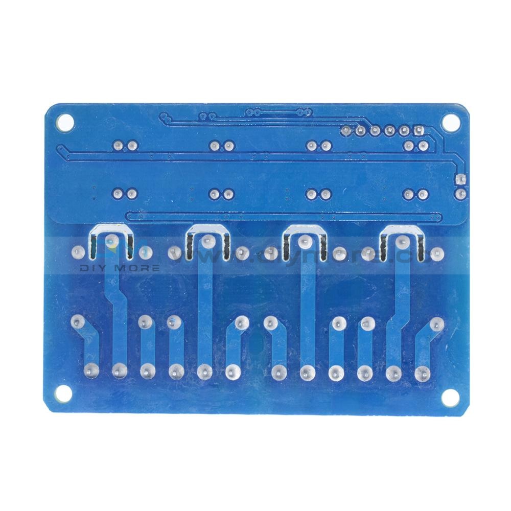
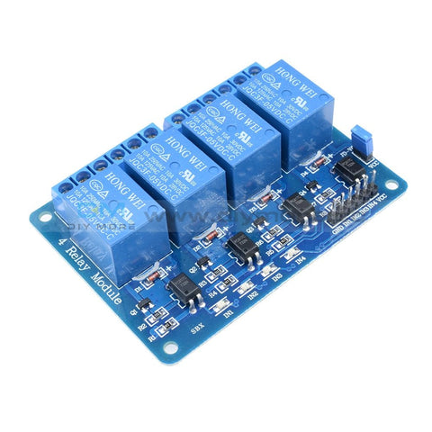 Translation missing: en.products.product.regular_price $6.99{"id":4896534233159,"title":"DC 24V 4 Channel Relay Control Switch RS485\/TTL Anti-reverse Connection Module","handle":"dc-24v-4-channel-relay-control-switch-rs485-ttl-anti-reverse-connection-module","description":"\u003cdiv data-mce-fragment=\"1\"\u003e\u003cspan lang=\"en\" data-mce-fragment=\"1\"\u003e\u003cstrong data-mce-fragment=\"1\"\u003eOverview:\u003c\/strong\u003e\u003c\/span\u003e\u003c\/div\u003e\n\u003cdiv data-mce-fragment=\"1\"\u003e\n\u003cul\u003e\n\u003cli\u003e\u003cspan lang=\"en\" data-mce-fragment=\"1\"\u003eElsay four-way Modbus relay module is equipped with mature and stable 8-bit MCU and RS485 level communication chip. Using standard MODBUS RTU format RS485 communication protocol, it can realize 4 input signal detection and 4 relay output, which can be used for digital detection or power control occasions.\u003c\/span\u003e\u003c\/li\u003e\n\u003c\/ul\u003e\n\u003cspan lang=\"en\" data-mce-fragment=\"1\"\u003e\u003cspan lang=\"en\" data-mce-fragment=\"1\"\u003e\u003cstrong data-mce-fragment=\"1\"\u003eFeatures:\u003c\/strong\u003e\u003cbr data-mce-fragment=\"1\"\u003e\u003c\/span\u003e\u003c\/span\u003e\n\u003cul\u003e\n\u003cli\u003e\u003cspan lang=\"en\" data-mce-fragment=\"1\"\u003eOnboard mature and stable 8bit MCU and MAX485 level conversion chip;\u003c\/span\u003e\u003c\/li\u003e\n\u003cli\u003e\u003cspan lang=\"en\" data-mce-fragment=\"1\"\u003eCommunication protocol: support standard Modbus RTU protocol;\u003c\/span\u003e\u003c\/li\u003e\n\u003cli\u003e\u003cspan lang=\"en\" data-mce-fragment=\"1\"\u003eCommunication interface: support RS485\/TTL UART interface;\u003c\/span\u003e\u003c\/li\u003e\n\u003cli\u003e\u003cspan lang=\"en\" data-mce-fragment=\"1\"\u003eCommunication baud rate: 4800\/9600\/19200, the default is 9600bps, and it supports power-off save;\u003c\/span\u003e\u003c\/li\u003e\n\u003cli\u003e\u003cspan lang=\"en\" data-mce-fragment=\"1\"\u003eOptocoupler input signal range: DC3.3-30V (this input cannot be used for relay control);\u003c\/span\u003e\u003c\/li\u003e\n\u003cli\u003e\u003cspan lang=\"en\" data-mce-fragment=\"1\"\u003eOutput signal: relay switch signal, support manual, flash off, flash off mode, flash off\/flash off delay base is 0.1S, the maximum flash off\/flash off time can be set to 0xFFFF*0.1S=6553.5S;\u003c\/span\u003e\u003c\/li\u003e\n\u003cli\u003e\u003cspan lang=\"en\" data-mce-fragment=\"1\"\u003eDevice address: range 1-255, default 255, support power-off save;\u003c\/span\u003e\u003c\/li\u003e\n\u003cli\u003e\u003cspan lang=\"en\" data-mce-fragment=\"1\"\u003eThe baud rate, input signal, relay status, and device address can be read using software\/commands;\u003c\/span\u003e\u003c\/li\u003e\n\u003cli\u003e\u003cspan lang=\"en\" data-mce-fragment=\"1\"\u003eThere are 4 5V, 10A\/250V AC 10A\/30V DC relays on board, which can be activated continuously for 100,000 times, with diode effusion protection, and short response time;\u003c\/span\u003e\u003c\/li\u003e\n\u003cli\u003e\u003cspan lang=\"en\" data-mce-fragment=\"1\"\u003eOn-board relay switch indicator;\u003c\/span\u003e\u003c\/li\u003e\n\u003cli\u003e\u003cspan lang=\"en\" data-mce-fragment=\"1\"\u003ePower supply voltage: DC7-24V, support DC socket\/5.08mm terminal power supply, with input anti-reverse protection;\u003c\/span\u003e\u003c\/li\u003e\n\u003c\/ul\u003e\n\u003c\/div\u003e\n\u003cdiv data-mce-fragment=\"1\"\u003e\u003cspan data-mce-fragment=\"1\"\u003e\u003cstrong data-mce-fragment=\"1\"\u003e\u003cspan lang=\"en\" data-mce-fragment=\"1\"\u003e\u003cspan title=\"\" data-mce-fragment=\"1\"\u003eHardware introduction and description\u003c\/span\u003e\u003c\/span\u003e\u003c\/strong\u003e\u003c\/span\u003e\u003c\/div\u003e\n\u003cdiv data-mce-fragment=\"1\"\u003e\u003cspan lang=\"en\" data-mce-fragment=\"1\"\u003e\u003cspan title=\"\" data-mce-fragment=\"1\"\u003eBoard size\u003c\/span\u003e\u003c\/span\u003e\u003c\/div\u003e\n\u003cdiv data-mce-fragment=\"1\"\u003e\u003cspan lang=\"en\" data-mce-fragment=\"1\"\u003e\u003cspan title=\"\" data-mce-fragment=\"1\"\u003e\u003cimg src=\"https:\/\/pg-cdn-a2.datacaciques.com\/00\/NDAy\/20\/10\/27\/759miw180130a6g1\/f50580d1c231c450.jpg\" data-mce-fragment=\"1\" data-mce-src=\"https:\/\/pg-cdn-a2.datacaciques.com\/00\/NDAy\/20\/10\/27\/759miw180130a6g1\/f50580d1c231c450.jpg\"\u003e\u003c\/span\u003e\u003c\/span\u003e\u003c\/div\u003e\n\u003cdiv data-mce-fragment=\"1\"\u003e\u003cspan lang=\"en\" data-mce-fragment=\"1\"\u003e\u003cspan title=\"\" data-mce-fragment=\"1\"\u003eInterface introduction\u003c\/span\u003e\u003c\/span\u003e\u003c\/div\u003e\n\u003cdiv data-mce-fragment=\"1\"\u003e\u003cspan lang=\"en\" data-mce-fragment=\"1\"\u003e\u003cspan title=\"\" data-mce-fragment=\"1\"\u003e\u003cimg src=\"https:\/\/pg-cdn-a2.datacaciques.com\/00\/NDAy\/20\/10\/27\/759miw180130a6g1\/4bc7a5d2ad0c45a2.jpg\" data-mce-fragment=\"1\" data-mce-src=\"https:\/\/pg-cdn-a2.datacaciques.com\/00\/NDAy\/20\/10\/27\/759miw180130a6g1\/4bc7a5d2ad0c45a2.jpg\"\u003e\u003c\/span\u003e\u003c\/span\u003e\u003c\/div\u003e\n\u003cdiv data-mce-fragment=\"1\"\u003e\n\u003cul\u003e\n\u003cli\u003e\u003cspan lang=\"en\" data-mce-fragment=\"1\"\u003e\u003cspan title=\"\" data-mce-fragment=\"1\"\u003eDC-005 socket: DC7-24V power input socket;\u003c\/span\u003e\u003c\/span\u003e\u003c\/li\u003e\n\u003cli\u003e\u003cspan lang=\"en\" data-mce-fragment=\"1\"\u003e\u003cspan title=\"\" data-mce-fragment=\"1\"\u003eVCC, GND: DC7-24V 5.08mm power input terminal;\u003c\/span\u003e\u003c\/span\u003e\u003c\/li\u003e\n\u003cli\u003e\u003cspan lang=\"en\" data-mce-fragment=\"1\"\u003e\u003cspan title=\"\" data-mce-fragment=\"1\"\u003eDC3.3-30V optocoupler signal input:\u003c\/span\u003e\u003c\/span\u003e\u003c\/li\u003e\n\u003cli\u003e\u003cspan lang=\"en\" data-mce-fragment=\"1\"\u003e\u003cspan title=\"\" data-mce-fragment=\"1\"\u003eIN1: Channel 1 positive\u003c\/span\u003e\u003c\/span\u003e\u003c\/li\u003e\n\u003cli\u003e\u003cspan lang=\"en\" data-mce-fragment=\"1\"\u003e\u003cspan title=\"\" data-mce-fragment=\"1\"\u003eIN2: Channel 2 positive\u003c\/span\u003e\u003c\/span\u003e\u003c\/li\u003e\n\u003cli\u003e\u003cspan lang=\"en\" data-mce-fragment=\"1\"\u003e\u003cspan title=\"\" data-mce-fragment=\"1\"\u003eIN3: Channel 3 positive\u003c\/span\u003e\u003c\/span\u003e\u003c\/li\u003e\n\u003cli\u003e\u003cspan lang=\"en\" data-mce-fragment=\"1\"\u003e\u003cspan title=\"\" data-mce-fragment=\"1\"\u003eIN4: Channel 4 positive\u003c\/span\u003e\u003c\/span\u003e\u003c\/li\u003e\n\u003cli\u003e\u003cspan lang=\"en\" data-mce-fragment=\"1\"\u003e\u003cspan title=\"\" data-mce-fragment=\"1\"\u003eGND_IN: Common terminal negative\u003c\/span\u003e\u003c\/span\u003e\u003c\/li\u003e\n\u003cli\u003e\u003cspan lang=\"en\" data-mce-fragment=\"1\"\u003e\u003cspan title=\"\" data-mce-fragment=\"1\"\u003eA+, B-: RS485 communication interface, A+, B- are respectively connected to A+, B- of the external control terminal;\u003c\/span\u003e\u003c\/span\u003e\u003c\/li\u003e\n\u003c\/ul\u003e\n\u003cspan lang=\"en\" data-mce-fragment=\"1\"\u003e\u003cspan lang=\"en\" data-mce-fragment=\"1\"\u003e\u003cspan title=\"\" data-mce-fragment=\"1\"\u003e\u003cstrong\u003eRelay switch signal output:\u003c\/strong\u003e\u003cbr data-mce-fragment=\"1\"\u003e\u003c\/span\u003e\u003c\/span\u003e\u003c\/span\u003e\n\u003cul\u003e\n\u003cli\u003e\u003cspan lang=\"en\" data-mce-fragment=\"1\"\u003e\u003cspan title=\"\" data-mce-fragment=\"1\"\u003eNC: Normally closed terminal, the relay is short-connected with COM before it is closed, and it is suspended after it is closed;\u003c\/span\u003e\u003c\/span\u003e\u003c\/li\u003e\n\u003cli\u003e\u003cspan lang=\"en\" data-mce-fragment=\"1\"\u003e\u003cspan title=\"\" data-mce-fragment=\"1\"\u003eCOM: public end;\u003c\/span\u003e\u003c\/span\u003e\u003c\/li\u003e\n\u003cli\u003e\u003cspan lang=\"en\" data-mce-fragment=\"1\"\u003e\u003cspan title=\"\" data-mce-fragment=\"1\"\u003eNO: Normally open end, the relay is suspended before closing, and shorted to COM after closing.\u003c\/span\u003e\u003c\/span\u003e\u003c\/li\u003e\n\u003cli\u003e\u003cspan lang=\"en\" data-mce-fragment=\"1\"\u003e\u003cspan title=\"\" data-mce-fragment=\"1\"\u003e6, GND, RXD, TXD: TTL level UART communication interface, GND, RXD, TXD are respectively connected to GND, TXD, RXD of the external control terminal;\u003c\/span\u003e\u003c\/span\u003e\u003c\/li\u003e\n\u003c\/ul\u003e\n\u003c\/div\u003e\n\u003cdiv data-mce-fragment=\"1\"\u003e\n\u003cspan lang=\"en\" data-mce-fragment=\"1\"\u003e\u003cspan lang=\"en\" data-mce-fragment=\"1\"\u003e\u003cspan title=\"\" data-mce-fragment=\"1\"\u003e\u003cstrong data-mce-fragment=\"1\"\u003eProduct Parameters:\u003c\/strong\u003e\u003cbr data-mce-fragment=\"1\"\u003e\u003c\/span\u003e\u003c\/span\u003e\u003c\/span\u003e\n\u003cul\u003e\n\u003cli\u003e\u003cspan lang=\"en\" data-mce-fragment=\"1\"\u003e\u003cspan title=\"\" data-mce-fragment=\"1\"\u003eItem name: 4CH Modbus Relay Module \u003c\/span\u003e\u003c\/span\u003e\u003c\/li\u003e\n\u003cli\u003e\u003cspan lang=\"en\" data-mce-fragment=\"1\"\u003e\u003cspan title=\"\" data-mce-fragment=\"1\"\u003eWork voltage:DC 7V~24V\u003c\/span\u003e\u003c\/span\u003e\u003c\/li\u003e\n\u003cli\u003e\u003cspan lang=\"en\" data-mce-fragment=\"1\"\u003e\u003cspan title=\"\" data-mce-fragment=\"1\"\u003eBaud rate:4800\/9600\/19600bps(default 9600bps)\u003c\/span\u003e\u003c\/span\u003e\u003c\/li\u003e\n\u003cli\u003e\u003cspan lang=\"en\" data-mce-fragment=\"1\"\u003e\u003cspan title=\"\" data-mce-fragment=\"1\"\u003eOptocoupler input signal:DC 3.3V~30V\u003c\/span\u003e\u003c\/span\u003e\u003c\/li\u003e\n\u003cli\u003e\u003cspan lang=\"en\" data-mce-fragment=\"1\"\u003e\u003cspan title=\"\" data-mce-fragment=\"1\"\u003eSet address:1~255\u003c\/span\u003e\u003c\/span\u003e\u003c\/li\u003e\n\u003cli\u003e\u003cspan lang=\"en\" data-mce-fragment=\"1\"\u003e\u003cspan title=\"\" data-mce-fragment=\"1\"\u003eRelay contorl mode: ON\/OFF,Delay_ON,Delay_OFF mode\u003c\/span\u003e\u003c\/span\u003e\u003c\/li\u003e\n\u003cli\u003e\u003cspan lang=\"en\" data-mce-fragment=\"1\"\u003e\u003cspan title=\"\" data-mce-fragment=\"1\"\u003eDelay time: 0~6553.5s \u003c\/span\u003e\u003c\/span\u003e\u003c\/li\u003e\n\u003cli\u003e\u003cspan lang=\"en\" data-mce-fragment=\"1\"\u003e\u003cspan title=\"\" data-mce-fragment=\"1\"\u003eLoad: AC 250V 10A or DC 28V 10A\u003c\/span\u003e\u003c\/span\u003e\u003c\/li\u003e\n\u003cli\u003e\u003cspan lang=\"en\" data-mce-fragment=\"1\"\u003e\u003cspan title=\"\" data-mce-fragment=\"1\"\u003eProtocol:Modbus RTU\u003c\/span\u003e\u003c\/span\u003e\u003c\/li\u003e\n\u003cli\u003e\u003cspan lang=\"en\" data-mce-fragment=\"1\"\u003e\u003cspan title=\"\" data-mce-fragment=\"1\"\u003eInterface:RS485\/TTL UART\u003c\/span\u003e\u003c\/span\u003e\u003c\/li\u003e\n\u003cli\u003e\u003cspan lang=\"en\" data-mce-fragment=\"1\"\u003e\u003cspan title=\"\" data-mce-fragment=\"1\"\u003eControl channel: 4channel\u003c\/span\u003e\u003c\/span\u003e\u003c\/li\u003e\n\u003cli\u003e\u003cspan lang=\"en\" data-mce-fragment=\"1\"\u003e\u003cspan title=\"\" data-mce-fragment=\"1\"\u003eOperating Temperature:-20℃~85℃\u003c\/span\u003e\u003c\/span\u003e\u003c\/li\u003e\n\u003cli\u003e\u003cspan lang=\"en\" data-mce-fragment=\"1\"\u003e\u003cspan title=\"\" data-mce-fragment=\"1\"\u003eOperating Humidity:5%~95%RH\u003c\/span\u003e\u003c\/span\u003e\u003c\/li\u003e\n\u003cli\u003e\u003cspan lang=\"en\" data-mce-fragment=\"1\"\u003e\u003cspan title=\"\" data-mce-fragment=\"1\"\u003eModule Size:93*90*20mm\u003c\/span\u003e\u003c\/span\u003e\u003c\/li\u003e\n\u003c\/ul\u003e\n\u003cspan lang=\"en\" data-mce-fragment=\"1\"\u003e\u003cspan lang=\"en\" data-mce-fragment=\"1\"\u003e\u003cspan title=\"\" data-mce-fragment=\"1\"\u003e\u003cimg src=\"https:\/\/pg-cdn-a2.datacaciques.com\/00\/NDAy\/20\/10\/27\/759miw180130a6g1\/5a40dd1349231871.jpg\" data-mce-fragment=\"1\" data-mce-src=\"https:\/\/pg-cdn-a2.datacaciques.com\/00\/NDAy\/20\/10\/27\/759miw180130a6g1\/5a40dd1349231871.jpg\"\u003e\u003cbr data-mce-fragment=\"1\"\u003e\u003cstrong data-mce-fragment=\"1\"\u003eModbus RTU Command:\u003c\/strong\u003e\u003cbr data-mce-fragment=\"1\"\u003e\u003c\/span\u003e\u003c\/span\u003e\u003c\/span\u003e\n\u003cul\u003e\n\u003cli\u003e\u003cspan lang=\"en\" data-mce-fragment=\"1\"\u003e\u003cspan title=\"\" data-mce-fragment=\"1\"\u003eSuppose the device address is 0xFF so return 00 10 00 00 00 01 02 00 FF EB 80 and the 9th btye is device address.\u003c\/span\u003e\u003c\/span\u003e\u003c\/li\u003e\n\u003cli\u003e\u003cspan lang=\"en\" data-mce-fragment=\"1\"\u003e\u003cspan title=\"\" data-mce-fragment=\"1\"\u003eTurn ON CH_1 Relay(Normal Mode):\u003c\/span\u003e\u003c\/span\u003e\u003c\/li\u003e\n\u003cli\u003e\u003cspan lang=\"en\" data-mce-fragment=\"1\"\u003e\u003cspan title=\"\" data-mce-fragment=\"1\"\u003e Send: FF 05 00 00 FF 00 99 E4\u003c\/span\u003e\u003c\/span\u003e\u003c\/li\u003e\n\u003cli\u003e\u003cspan lang=\"en\" data-mce-fragment=\"1\"\u003e\u003cspan title=\"\" data-mce-fragment=\"1\"\u003e Return: FF 05 00 00 FF 00 99 E4\u003c\/span\u003e\u003c\/span\u003e\u003c\/li\u003e\n\u003cli\u003e\u003cspan lang=\"en\" data-mce-fragment=\"1\"\u003e\u003cspan title=\"\" data-mce-fragment=\"1\"\u003e Note_1:The 3rd and 4th byte are relay addresses.So it can be 0x0000,0x0001,0x0002,0x0003.\u003c\/span\u003e\u003c\/span\u003e\u003c\/li\u003e\n\u003cli\u003e\u003cspan lang=\"en\" data-mce-fragment=\"1\"\u003e\u003cspan title=\"\" data-mce-fragment=\"1\"\u003e Note_2:The 5th and 6th byte are relay data.0xFF00 means turn ON relay and 0x0000 means turn OFF relay.\u003c\/span\u003e\u003c\/span\u003e\u003c\/li\u003e\n\u003cli\u003e\u003cspan lang=\"en\" data-mce-fragment=\"1\"\u003e\u003cspan title=\"\" data-mce-fragment=\"1\"\u003eTurn OFF CH_1 Relay(Normal Mode):\u003c\/span\u003e\u003c\/span\u003e\u003c\/li\u003e\n\u003cli\u003e\u003cspan lang=\"en\" data-mce-fragment=\"1\"\u003e\u003cspan title=\"\" data-mce-fragment=\"1\"\u003e Send: FF 05 00 00 00 00 D8 14\u003c\/span\u003e\u003c\/span\u003e\u003c\/li\u003e\n\u003cli\u003e\u003cspan lang=\"en\" data-mce-fragment=\"1\"\u003e\u003cspan title=\"\" data-mce-fragment=\"1\"\u003e Return: FF 05 00 00 00 00 D8 14\u003c\/span\u003e\u003c\/span\u003e\u003c\/li\u003e\n\u003cli\u003e\u003cspan lang=\"en\" data-mce-fragment=\"1\"\u003e\u003cspan title=\"\" data-mce-fragment=\"1\"\u003eTurn ON CH_2 Relay(Normal Mode):\u003c\/span\u003e\u003c\/span\u003e\u003c\/li\u003e\n\u003cli\u003e\u003cspan lang=\"en\" data-mce-fragment=\"1\"\u003e\u003cspan title=\"\" data-mce-fragment=\"1\"\u003e Send: FF 05 00 01 FF 00 C8 24\u003c\/span\u003e\u003c\/span\u003e\u003c\/li\u003e\n\u003cli\u003e\u003cspan lang=\"en\" data-mce-fragment=\"1\"\u003e\u003cspan title=\"\" data-mce-fragment=\"1\"\u003e Return: FF 05 00 01 FF 00 C8 24\u003c\/span\u003e\u003c\/span\u003e\u003c\/li\u003e\n\u003cli\u003e\u003cspan lang=\"en\" data-mce-fragment=\"1\"\u003e\u003cspan title=\"\" data-mce-fragment=\"1\"\u003eTurn OFF CH_2 Relay(Normal Mode):\u003c\/span\u003e\u003c\/span\u003e\u003c\/li\u003e\n\u003cli\u003e\u003cspan lang=\"en\" data-mce-fragment=\"1\"\u003e\u003cspan title=\"\" data-mce-fragment=\"1\"\u003e Send: FF 05 00 01 00 00 89 D4\u003c\/span\u003e\u003c\/span\u003e\u003c\/li\u003e\n\u003cli\u003e\u003cspan lang=\"en\" data-mce-fragment=\"1\"\u003e\u003cspan title=\"\" data-mce-fragment=\"1\"\u003e Return: FF 05 00 01 00 00 89 D4\u003c\/span\u003e\u003c\/span\u003e\u003c\/li\u003e\n\u003cli\u003e\u003cspan lang=\"en\" data-mce-fragment=\"1\"\u003e\u003cspan title=\"\" data-mce-fragment=\"1\"\u003eTurn ON All relays:\u003c\/span\u003e\u003c\/span\u003e\u003c\/li\u003e\n\u003cli\u003e\u003cspan lang=\"en\" data-mce-fragment=\"1\"\u003e\u003cspan title=\"\" data-mce-fragment=\"1\"\u003e Send: FF 0F 00 00 00 08 01 FF 30 1D\u003c\/span\u003e\u003c\/span\u003e\u003c\/li\u003e\n\u003cli\u003e\u003cspan lang=\"en\" data-mce-fragment=\"1\"\u003e\u003cspan title=\"\" data-mce-fragment=\"1\"\u003e Return: FF 0F 00 00 00 08 41 D3\u003c\/span\u003e\u003c\/span\u003e\u003c\/li\u003e\n\u003cli\u003e\u003cspan lang=\"en\" data-mce-fragment=\"1\"\u003e\u003cspan title=\"\" data-mce-fragment=\"1\"\u003eTurn OFF All relays:\u003c\/span\u003e\u003c\/span\u003e\u003c\/li\u003e\n\u003cli\u003e\u003cspan lang=\"en\" data-mce-fragment=\"1\"\u003e\u003cspan title=\"\" data-mce-fragment=\"1\"\u003e Send: FF 0F 00 00 00 08 01 00 70 5D\u003c\/span\u003e\u003c\/span\u003e\u003c\/li\u003e\n\u003cli\u003e\u003cspan lang=\"en\" data-mce-fragment=\"1\"\u003e\u003cspan title=\"\" data-mce-fragment=\"1\"\u003e Return: FF 0F 00 00 00 08 41 D3\u003c\/span\u003e\u003c\/span\u003e\u003c\/li\u003e\n\u003cli\u003e\u003cspan lang=\"en\" data-mce-fragment=\"1\"\u003e\u003cspan title=\"\" data-mce-fragment=\"1\"\u003eSet device address to 0x01:\u003c\/span\u003e\u003c\/span\u003e\u003c\/li\u003e\n\u003cli\u003e\u003cspan lang=\"en\" data-mce-fragment=\"1\"\u003e\u003cspan title=\"\" data-mce-fragment=\"1\"\u003e Send: 00 10 00 00 00 01 02 00 01 6A 00\u003c\/span\u003e\u003c\/span\u003e\u003c\/li\u003e\n\u003cli\u003e\u003cspan lang=\"en\" data-mce-fragment=\"1\"\u003e\u003cspan title=\"\" data-mce-fragment=\"1\"\u003e Return: 00 10 00 00 00 01 02 00 01 6A 00\u003c\/span\u003e\u003c\/span\u003e\u003c\/li\u003e\n\u003cli\u003e\u003cspan lang=\"en\" data-mce-fragment=\"1\"\u003e\u003cspan title=\"\" data-mce-fragment=\"1\"\u003e Note: The 9th btye is device address.\u003c\/span\u003e\u003c\/span\u003e\u003c\/li\u003e\n\u003cli\u003e\u003cspan lang=\"en\" data-mce-fragment=\"1\"\u003e\u003cspan title=\"\" data-mce-fragment=\"1\"\u003eSet device address to 0xFF:\u003c\/span\u003e\u003c\/span\u003e\u003c\/li\u003e\n\u003cli\u003e\u003cspan lang=\"en\" data-mce-fragment=\"1\"\u003e\u003cspan title=\"\" data-mce-fragment=\"1\"\u003e Send: 00 10 00 00 00 01 02 00 FF EB 80\u003c\/span\u003e\u003c\/span\u003e\u003c\/li\u003e\n\u003cli\u003e\u003cspan lang=\"en\" data-mce-fragment=\"1\"\u003e\u003cspan title=\"\" data-mce-fragment=\"1\"\u003e Return: 00 10 00 00 00 01 02 00 FF EB 80\u003c\/span\u003e\u003c\/span\u003e\u003c\/li\u003e\n\u003cli\u003e\u003cspan lang=\"en\" data-mce-fragment=\"1\"\u003e\u003cspan title=\"\" data-mce-fragment=\"1\"\u003eRead device address:\u003c\/span\u003e\u003c\/span\u003e\u003c\/li\u003e\n\u003cli\u003e\u003cspan lang=\"en\" data-mce-fragment=\"1\"\u003e\u003cspan title=\"\" data-mce-fragment=\"1\"\u003e Send: 00 03 00 00 00 01 85 DB\u003c\/span\u003e\u003c\/span\u003e\u003c\/li\u003e\n\u003cli\u003e\u003cspan lang=\"en\" data-mce-fragment=\"1\"\u003e\u003cspan title=\"\" data-mce-fragment=\"1\"\u003e Return: 00 03 02 00 FF C5 C4\u003c\/span\u003e\u003c\/span\u003e\u003c\/li\u003e\n\u003cli\u003e\u003cspan lang=\"en\" data-mce-fragment=\"1\"\u003e\u003cspan title=\"\" data-mce-fragment=\"1\"\u003e Note: The 5th btye is device address.\u003c\/span\u003e\u003c\/span\u003e\u003c\/li\u003e\n\u003cli\u003e\u003cspan lang=\"en\" data-mce-fragment=\"1\"\u003e\u003cspan title=\"\" data-mce-fragment=\"1\"\u003eRead relay status:\u003c\/span\u003e\u003c\/span\u003e\u003c\/li\u003e\n\u003cli\u003e\u003cspan lang=\"en\" data-mce-fragment=\"1\"\u003e\u003cspan title=\"\" data-mce-fragment=\"1\"\u003e Send: FF 01 00 00 00 08 28 12\u003c\/span\u003e\u003c\/span\u003e\u003c\/li\u003e\n\u003cli\u003e\u003cspan lang=\"en\" data-mce-fragment=\"1\"\u003e\u003cspan title=\"\" data-mce-fragment=\"1\"\u003e Return: FF 01 01 01 A1 A0\u003c\/span\u003e\u003c\/span\u003e\u003c\/li\u003e\n\u003cli\u003e\u003cspan lang=\"en\" data-mce-fragment=\"1\"\u003e\u003cspan title=\"\" data-mce-fragment=\"1\"\u003e Note:The 4th means which one relay.0 means OFF and 1 means ON.\u003c\/span\u003e\u003c\/span\u003e\u003c\/li\u003e\n\u003cli\u003e\u003cspan lang=\"en\" data-mce-fragment=\"1\"\u003e\u003cspan title=\"\" data-mce-fragment=\"1\"\u003eRead optocoupler input staturs:\u003c\/span\u003e\u003c\/span\u003e\u003c\/li\u003e\n\u003cli\u003e\u003cspan lang=\"en\" data-mce-fragment=\"1\"\u003e\u003cspan title=\"\" data-mce-fragment=\"1\"\u003e Send: FF 02 00 00 00 08 6C 12\u003c\/span\u003e\u003c\/span\u003e\u003c\/li\u003e\n\u003cli\u003e\u003cspan lang=\"en\" data-mce-fragment=\"1\"\u003e\u003cspan title=\"\" data-mce-fragment=\"1\"\u003e Return: FF 02 01 01 51 A0\u003c\/span\u003e\u003c\/span\u003e\u003c\/li\u003e\n\u003cli\u003e\u003cspan lang=\"en\" data-mce-fragment=\"1\"\u003e\u003cspan title=\"\" data-mce-fragment=\"1\"\u003e Note:The 4th means which one input.0 means low level signal input and 1 means high level signal input.\u003c\/span\u003e\u003c\/span\u003e\u003c\/li\u003e\n\u003cli\u003e\u003cspan lang=\"en\" data-mce-fragment=\"1\"\u003e\u003cspan title=\"\" data-mce-fragment=\"1\"\u003eSet baud rate 4800bps:\u003c\/span\u003e\u003c\/span\u003e\u003c\/li\u003e\n\u003cli\u003e\u003cspan lang=\"en\" data-mce-fragment=\"1\"\u003e\u003cspan title=\"\" data-mce-fragment=\"1\"\u003e Send: FF 10 03 E9 00 01 02 00 02 4A 0C\u003c\/span\u003e\u003c\/span\u003e\u003c\/li\u003e\n\u003cli\u003e\u003cspan lang=\"en\" data-mce-fragment=\"1\"\u003e\u003cspan title=\"\" data-mce-fragment=\"1\"\u003e Return: FF 10 03 E9 00 01 C5 A7\u003c\/span\u003e\u003c\/span\u003e\u003c\/li\u003e\n\u003cli\u003e\u003cspan lang=\"en\" data-mce-fragment=\"1\"\u003e\u003cspan title=\"\" data-mce-fragment=\"1\"\u003e Note:The 9th btye is baud rate value.0x02 is 4800bps.0x03 is 9600bps.0x04 is 19200bps.\u003c\/span\u003e\u003c\/span\u003e\u003c\/li\u003e\n\u003cli\u003e\u003cspan lang=\"en\" data-mce-fragment=\"1\"\u003e\u003cspan title=\"\" data-mce-fragment=\"1\"\u003eSet baud rate 9600bps:\u003c\/span\u003e\u003c\/span\u003e\u003c\/li\u003e\n\u003cli\u003e\u003cspan lang=\"en\" data-mce-fragment=\"1\"\u003e\u003cspan title=\"\" data-mce-fragment=\"1\"\u003e Send: FF 10 03 E9 00 01 02 00 03 8B CC\u003c\/span\u003e\u003c\/span\u003e\u003c\/li\u003e\n\u003cli\u003e\u003cspan lang=\"en\" data-mce-fragment=\"1\"\u003e\u003cspan title=\"\" data-mce-fragment=\"1\"\u003e Return: FF 10 03 E9 00 01 C5 A7\u003c\/span\u003e\u003c\/span\u003e\u003c\/li\u003e\n\u003cli\u003e\u003cspan lang=\"en\" data-mce-fragment=\"1\"\u003e\u003cspan title=\"\" data-mce-fragment=\"1\"\u003eSet baud rate 19200bps:\u003c\/span\u003e\u003c\/span\u003e\u003c\/li\u003e\n\u003cli\u003e\u003cspan lang=\"en\" data-mce-fragment=\"1\"\u003e\u003cspan title=\"\" data-mce-fragment=\"1\"\u003e Send: FF 10 03 E9 00 01 02 00 04 CA 0E\u003c\/span\u003e\u003c\/span\u003e\u003c\/li\u003e\n\u003cli\u003e\u003cspan lang=\"en\" data-mce-fragment=\"1\"\u003e\u003cspan title=\"\" data-mce-fragment=\"1\"\u003e Return: FF 10 03 E9 00 01 C5 A7\u003c\/span\u003e\u003c\/span\u003e\u003c\/li\u003e\n\u003cli\u003e\u003cspan lang=\"en\" data-mce-fragment=\"1\"\u003e\u003cspan title=\"\" data-mce-fragment=\"1\"\u003eTurn ON CH_1 Relay(2S Flashing Mode):\u003c\/span\u003e\u003c\/span\u003e\u003c\/li\u003e\n\u003cli\u003e\u003cspan lang=\"en\" data-mce-fragment=\"1\"\u003e\u003cspan title=\"\" data-mce-fragment=\"1\"\u003e Send: FF 10 00 03 00 02 04 00 04 00 14 C5 9F\u003c\/span\u003e\u003c\/span\u003e\u003c\/li\u003e\n\u003cli\u003e\u003cspan lang=\"en\" data-mce-fragment=\"1\"\u003e\u003cspan title=\"\" data-mce-fragment=\"1\"\u003e Return: FF 10 00 03 00 02 A4 16\u003c\/span\u003e\u003c\/span\u003e\u003c\/li\u003e\n\u003cli\u003e\u003cspan lang=\"en\" data-mce-fragment=\"1\"\u003e\u003cspan title=\"\" data-mce-fragment=\"1\"\u003e Note_1:The 3rd and 4th byte are relay addresses.So CH1~CH4 can be 0x0003,0x0008,0x000D,0x0012.\u003c\/span\u003e\u003c\/span\u003e\u003c\/li\u003e\n\u003cli\u003e\u003cspan lang=\"en\" data-mce-fragment=\"1\"\u003e\u003cspan title=\"\" data-mce-fragment=\"1\"\u003e Note_2:The 10th and 11th byte are delay time in second.The minimum delay time is 0.1s.Relay will OFF after delay time.So the delay time in this command is : 0x0014*0.1=2S.\u003c\/span\u003e\u003c\/span\u003e\u003c\/li\u003e\n\u003cli\u003e\u003cspan lang=\"en\" data-mce-fragment=\"1\"\u003e\u003cspan title=\"\" data-mce-fragment=\"1\"\u003eTurn OFF CH_1 Relay(3S Flashing Mode):\u003c\/span\u003e\u003c\/span\u003e\u003c\/li\u003e\n\u003cli\u003e\u003cspan lang=\"en\" data-mce-fragment=\"1\"\u003e\u003cspan title=\"\" data-mce-fragment=\"1\"\u003e Send: FF 10 00 03 00 02 04 00 02 00 1E A5 99\u003c\/span\u003e\u003c\/span\u003e\u003c\/li\u003e\n\u003cli\u003e\u003cspan lang=\"en\" data-mce-fragment=\"1\"\u003e\u003cspan title=\"\" data-mce-fragment=\"1\"\u003e Return: FF 10 00 03 00 02 A4 16\u003c\/span\u003e\u003c\/span\u003e\u003c\/li\u003e\n\u003cli\u003e\u003cspan lang=\"en\" data-mce-fragment=\"1\"\u003e\u003cspan title=\"\" data-mce-fragment=\"1\"\u003e Note:Relay will ON after delay time.So the delay time in this command is : 0x001E*0.1=3S.\u003c\/span\u003e\u003c\/span\u003e\u003c\/li\u003e\n\u003c\/ul\u003e\n\u003cspan lang=\"en\" data-mce-fragment=\"1\"\u003e\u003cspan lang=\"en\" data-mce-fragment=\"1\"\u003e\u003cspan title=\"\" data-mce-fragment=\"1\"\u003e\u003cimg src=\"https:\/\/pg-cdn-a2.datacaciques.com\/00\/NDAy\/20\/10\/27\/759miw180130a6g1\/b4e1c2017abb1ec6.jpg\" data-mce-fragment=\"1\" data-mce-src=\"https:\/\/pg-cdn-a2.datacaciques.com\/00\/NDAy\/20\/10\/27\/759miw180130a6g1\/b4e1c2017abb1ec6.jpg\"\u003e\u003cbr data-mce-fragment=\"1\"\u003e\u003cstrong data-mce-fragment=\"1\"\u003ePackage Include:\u003c\/strong\u003e\u003cbr data-mce-fragment=\"1\"\u003e\u003c\/span\u003e\u003c\/span\u003e\u003c\/span\u003e\n\u003cul\u003e\n\u003cli\u003e\u003cspan lang=\"en\" data-mce-fragment=\"1\"\u003e\u003cspan title=\"\" data-mce-fragment=\"1\"\u003e 1PC 4CH Modbus Relay Module \u003c\/span\u003e\u003c\/span\u003e\u003c\/li\u003e\n\u003c\/ul\u003e\n\u003c\/div\u003e\n\u003cdiv data-mce-fragment=\"1\"\u003e\u003cspan lang=\"en\" data-mce-fragment=\"1\"\u003e\u003cspan title=\"\" data-mce-fragment=\"1\"\u003e \u003c\/span\u003e\u003c\/span\u003e\u003c\/div\u003e","published_at":"2020-10-29T16:43:18+08:00","created_at":"2020-10-28T12:04:09+08:00","vendor":"DIYMORE","type":"","tags":[],"price":1099,"price_min":1099,"price_max":1099,"available":true,"price_varies":false,"compare_at_price":null,"compare_at_price_min":0,"compare_at_price_max":0,"compare_at_price_varies":false,"variants":[{"id":32644275765319,"title":"Default Title","option1":"Default Title","option2":null,"option3":null,"sku":"XM0006","requires_shipping":true,"taxable":false,"featured_image":null,"available":true,"name":"DC 24V 4 Channel Relay Control Switch RS485\/TTL Anti-reverse Connection Module","public_title":null,"options":["Default Title"],"price":1099,"weight":0,"compare_at_price":null,"inventory_management":"shopify","barcode":"","requires_selling_plan":false,"selling_plan_allocations":[],"quantity_rule":{"min":1,"max":null,"increment":1}}],"images":["\/\/www.diymore.cc\/cdn\/shop\/products\/3_c1c2716b-4e56-4778-96d4-eb4ff9c7620a.jpg?v=1603857853","\/\/www.diymore.cc\/cdn\/shop\/products\/5_ff208254-a902-4d04-93e4-bce5ea8eb512.jpg?v=1603857854","\/\/www.diymore.cc\/cdn\/shop\/products\/4_0b281e6a-ef90-4366-8a24-d9a167cf31ca.jpg?v=1603857854","\/\/www.diymore.cc\/cdn\/shop\/products\/1_968bb946-a0f2-4ed7-8618-2ab8b7fa26f9.jpg?v=1603857854","\/\/www.diymore.cc\/cdn\/shop\/products\/2_5f6abbf8-5697-4e69-9c60-03559cfb6029.jpg?v=1603857854"],"featured_image":"\/\/www.diymore.cc\/cdn\/shop\/products\/3_c1c2716b-4e56-4778-96d4-eb4ff9c7620a.jpg?v=1603857853","options":["Title"],"media":[{"alt":null,"id":7652174987335,"position":1,"preview_image":{"aspect_ratio":1.0,"height":1000,"width":1000,"src":"\/\/www.diymore.cc\/cdn\/shop\/products\/3_c1c2716b-4e56-4778-96d4-eb4ff9c7620a.jpg?v=1603857853"},"aspect_ratio":1.0,"height":1000,"media_type":"image","src":"\/\/www.diymore.cc\/cdn\/shop\/products\/3_c1c2716b-4e56-4778-96d4-eb4ff9c7620a.jpg?v=1603857853","width":1000},{"alt":null,"id":7652175020103,"position":2,"preview_image":{"aspect_ratio":1.0,"height":1000,"width":1000,"src":"\/\/www.diymore.cc\/cdn\/shop\/products\/5_ff208254-a902-4d04-93e4-bce5ea8eb512.jpg?v=1603857854"},"aspect_ratio":1.0,"height":1000,"media_type":"image","src":"\/\/www.diymore.cc\/cdn\/shop\/products\/5_ff208254-a902-4d04-93e4-bce5ea8eb512.jpg?v=1603857854","width":1000},{"alt":null,"id":7652175052871,"position":3,"preview_image":{"aspect_ratio":1.0,"height":1000,"width":1000,"src":"\/\/www.diymore.cc\/cdn\/shop\/products\/4_0b281e6a-ef90-4366-8a24-d9a167cf31ca.jpg?v=1603857854"},"aspect_ratio":1.0,"height":1000,"media_type":"image","src":"\/\/www.diymore.cc\/cdn\/shop\/products\/4_0b281e6a-ef90-4366-8a24-d9a167cf31ca.jpg?v=1603857854","width":1000},{"alt":null,"id":7652175085639,"position":4,"preview_image":{"aspect_ratio":1.0,"height":1000,"width":1000,"src":"\/\/www.diymore.cc\/cdn\/shop\/products\/1_968bb946-a0f2-4ed7-8618-2ab8b7fa26f9.jpg?v=1603857854"},"aspect_ratio":1.0,"height":1000,"media_type":"image","src":"\/\/www.diymore.cc\/cdn\/shop\/products\/1_968bb946-a0f2-4ed7-8618-2ab8b7fa26f9.jpg?v=1603857854","width":1000},{"alt":null,"id":7652175118407,"position":5,"preview_image":{"aspect_ratio":1.0,"height":1000,"width":1000,"src":"\/\/www.diymore.cc\/cdn\/shop\/products\/2_5f6abbf8-5697-4e69-9c60-03559cfb6029.jpg?v=1603857854"},"aspect_ratio":1.0,"height":1000,"media_type":"image","src":"\/\/www.diymore.cc\/cdn\/shop\/products\/2_5f6abbf8-5697-4e69-9c60-03559cfb6029.jpg?v=1603857854","width":1000}],"requires_selling_plan":false,"selling_plan_groups":[],"content":"\u003cdiv data-mce-fragment=\"1\"\u003e\u003cspan lang=\"en\" data-mce-fragment=\"1\"\u003e\u003cstrong data-mce-fragment=\"1\"\u003eOverview:\u003c\/strong\u003e\u003c\/span\u003e\u003c\/div\u003e\n\u003cdiv data-mce-fragment=\"1\"\u003e\n\u003cul\u003e\n\u003cli\u003e\u003cspan lang=\"en\" data-mce-fragment=\"1\"\u003eElsay four-way Modbus relay module is equipped with mature and stable 8-bit MCU and RS485 level communication chip. Using standard MODBUS RTU format RS485 communication protocol, it can realize 4 input signal detection and 4 relay output, which can be used for digital detection or power control occasions.\u003c\/span\u003e\u003c\/li\u003e\n\u003c\/ul\u003e\n\u003cspan lang=\"en\" data-mce-fragment=\"1\"\u003e\u003cspan lang=\"en\" data-mce-fragment=\"1\"\u003e\u003cstrong data-mce-fragment=\"1\"\u003eFeatures:\u003c\/strong\u003e\u003cbr data-mce-fragment=\"1\"\u003e\u003c\/span\u003e\u003c\/span\u003e\n\u003cul\u003e\n\u003cli\u003e\u003cspan lang=\"en\" data-mce-fragment=\"1\"\u003eOnboard mature and stable 8bit MCU and MAX485 level conversion chip;\u003c\/span\u003e\u003c\/li\u003e\n\u003cli\u003e\u003cspan lang=\"en\" data-mce-fragment=\"1\"\u003eCommunication protocol: support standard Modbus RTU protocol;\u003c\/span\u003e\u003c\/li\u003e\n\u003cli\u003e\u003cspan lang=\"en\" data-mce-fragment=\"1\"\u003eCommunication interface: support RS485\/TTL UART interface;\u003c\/span\u003e\u003c\/li\u003e\n\u003cli\u003e\u003cspan lang=\"en\" data-mce-fragment=\"1\"\u003eCommunication baud rate: 4800\/9600\/19200, the default is 9600bps, and it supports power-off save;\u003c\/span\u003e\u003c\/li\u003e\n\u003cli\u003e\u003cspan lang=\"en\" data-mce-fragment=\"1\"\u003eOptocoupler input signal range: DC3.3-30V (this input cannot be used for relay control);\u003c\/span\u003e\u003c\/li\u003e\n\u003cli\u003e\u003cspan lang=\"en\" data-mce-fragment=\"1\"\u003eOutput signal: relay switch signal, support manual, flash off, flash off mode, flash off\/flash off delay base is 0.1S, the maximum flash off\/flash off time can be set to 0xFFFF*0.1S=6553.5S;\u003c\/span\u003e\u003c\/li\u003e\n\u003cli\u003e\u003cspan lang=\"en\" data-mce-fragment=\"1\"\u003eDevice address: range 1-255, default 255, support power-off save;\u003c\/span\u003e\u003c\/li\u003e\n\u003cli\u003e\u003cspan lang=\"en\" data-mce-fragment=\"1\"\u003eThe baud rate, input signal, relay status, and device address can be read using software\/commands;\u003c\/span\u003e\u003c\/li\u003e\n\u003cli\u003e\u003cspan lang=\"en\" data-mce-fragment=\"1\"\u003eThere are 4 5V, 10A\/250V AC 10A\/30V DC relays on board, which can be activated continuously for 100,000 times, with diode effusion protection, and short response time;\u003c\/span\u003e\u003c\/li\u003e\n\u003cli\u003e\u003cspan lang=\"en\" data-mce-fragment=\"1\"\u003eOn-board relay switch indicator;\u003c\/span\u003e\u003c\/li\u003e\n\u003cli\u003e\u003cspan lang=\"en\" data-mce-fragment=\"1\"\u003ePower supply voltage: DC7-24V, support DC socket\/5.08mm terminal power supply, with input anti-reverse protection;\u003c\/span\u003e\u003c\/li\u003e\n\u003c\/ul\u003e\n\u003c\/div\u003e\n\u003cdiv data-mce-fragment=\"1\"\u003e\u003cspan data-mce-fragment=\"1\"\u003e\u003cstrong data-mce-fragment=\"1\"\u003e\u003cspan lang=\"en\" data-mce-fragment=\"1\"\u003e\u003cspan title=\"\" data-mce-fragment=\"1\"\u003eHardware introduction and description\u003c\/span\u003e\u003c\/span\u003e\u003c\/strong\u003e\u003c\/span\u003e\u003c\/div\u003e\n\u003cdiv data-mce-fragment=\"1\"\u003e\u003cspan lang=\"en\" data-mce-fragment=\"1\"\u003e\u003cspan title=\"\" data-mce-fragment=\"1\"\u003eBoard size\u003c\/span\u003e\u003c\/span\u003e\u003c\/div\u003e\n\u003cdiv data-mce-fragment=\"1\"\u003e\u003cspan lang=\"en\" data-mce-fragment=\"1\"\u003e\u003cspan title=\"\" data-mce-fragment=\"1\"\u003e\u003cimg src=\"https:\/\/pg-cdn-a2.datacaciques.com\/00\/NDAy\/20\/10\/27\/759miw180130a6g1\/f50580d1c231c450.jpg\" data-mce-fragment=\"1\" data-mce-src=\"https:\/\/pg-cdn-a2.datacaciques.com\/00\/NDAy\/20\/10\/27\/759miw180130a6g1\/f50580d1c231c450.jpg\"\u003e\u003c\/span\u003e\u003c\/span\u003e\u003c\/div\u003e\n\u003cdiv data-mce-fragment=\"1\"\u003e\u003cspan lang=\"en\" data-mce-fragment=\"1\"\u003e\u003cspan title=\"\" data-mce-fragment=\"1\"\u003eInterface introduction\u003c\/span\u003e\u003c\/span\u003e\u003c\/div\u003e\n\u003cdiv data-mce-fragment=\"1\"\u003e\u003cspan lang=\"en\" data-mce-fragment=\"1\"\u003e\u003cspan title=\"\" data-mce-fragment=\"1\"\u003e\u003cimg src=\"https:\/\/pg-cdn-a2.datacaciques.com\/00\/NDAy\/20\/10\/27\/759miw180130a6g1\/4bc7a5d2ad0c45a2.jpg\" data-mce-fragment=\"1\" data-mce-src=\"https:\/\/pg-cdn-a2.datacaciques.com\/00\/NDAy\/20\/10\/27\/759miw180130a6g1\/4bc7a5d2ad0c45a2.jpg\"\u003e\u003c\/span\u003e\u003c\/span\u003e\u003c\/div\u003e\n\u003cdiv data-mce-fragment=\"1\"\u003e\n\u003cul\u003e\n\u003cli\u003e\u003cspan lang=\"en\" data-mce-fragment=\"1\"\u003e\u003cspan title=\"\" data-mce-fragment=\"1\"\u003eDC-005 socket: DC7-24V power input socket;\u003c\/span\u003e\u003c\/span\u003e\u003c\/li\u003e\n\u003cli\u003e\u003cspan lang=\"en\" data-mce-fragment=\"1\"\u003e\u003cspan title=\"\" data-mce-fragment=\"1\"\u003eVCC, GND: DC7-24V 5.08mm power input terminal;\u003c\/span\u003e\u003c\/span\u003e\u003c\/li\u003e\n\u003cli\u003e\u003cspan lang=\"en\" data-mce-fragment=\"1\"\u003e\u003cspan title=\"\" data-mce-fragment=\"1\"\u003eDC3.3-30V optocoupler signal input:\u003c\/span\u003e\u003c\/span\u003e\u003c\/li\u003e\n\u003cli\u003e\u003cspan lang=\"en\" data-mce-fragment=\"1\"\u003e\u003cspan title=\"\" data-mce-fragment=\"1\"\u003eIN1: Channel 1 positive\u003c\/span\u003e\u003c\/span\u003e\u003c\/li\u003e\n\u003cli\u003e\u003cspan lang=\"en\" data-mce-fragment=\"1\"\u003e\u003cspan title=\"\" data-mce-fragment=\"1\"\u003eIN2: Channel 2 positive\u003c\/span\u003e\u003c\/span\u003e\u003c\/li\u003e\n\u003cli\u003e\u003cspan lang=\"en\" data-mce-fragment=\"1\"\u003e\u003cspan title=\"\" data-mce-fragment=\"1\"\u003eIN3: Channel 3 positive\u003c\/span\u003e\u003c\/span\u003e\u003c\/li\u003e\n\u003cli\u003e\u003cspan lang=\"en\" data-mce-fragment=\"1\"\u003e\u003cspan title=\"\" data-mce-fragment=\"1\"\u003eIN4: Channel 4 positive\u003c\/span\u003e\u003c\/span\u003e\u003c\/li\u003e\n\u003cli\u003e\u003cspan lang=\"en\" data-mce-fragment=\"1\"\u003e\u003cspan title=\"\" data-mce-fragment=\"1\"\u003eGND_IN: Common terminal negative\u003c\/span\u003e\u003c\/span\u003e\u003c\/li\u003e\n\u003cli\u003e\u003cspan lang=\"en\" data-mce-fragment=\"1\"\u003e\u003cspan title=\"\" data-mce-fragment=\"1\"\u003eA+, B-: RS485 communication interface, A+, B- are respectively connected to A+, B- of the external control terminal;\u003c\/span\u003e\u003c\/span\u003e\u003c\/li\u003e\n\u003c\/ul\u003e\n\u003cspan lang=\"en\" data-mce-fragment=\"1\"\u003e\u003cspan lang=\"en\" data-mce-fragment=\"1\"\u003e\u003cspan title=\"\" data-mce-fragment=\"1\"\u003e\u003cstrong\u003eRelay switch signal output:\u003c\/strong\u003e\u003cbr data-mce-fragment=\"1\"\u003e\u003c\/span\u003e\u003c\/span\u003e\u003c\/span\u003e\n\u003cul\u003e\n\u003cli\u003e\u003cspan lang=\"en\" data-mce-fragment=\"1\"\u003e\u003cspan title=\"\" data-mce-fragment=\"1\"\u003eNC: Normally closed terminal, the relay is short-connected with COM before it is closed, and it is suspended after it is closed;\u003c\/span\u003e\u003c\/span\u003e\u003c\/li\u003e\n\u003cli\u003e\u003cspan lang=\"en\" data-mce-fragment=\"1\"\u003e\u003cspan title=\"\" data-mce-fragment=\"1\"\u003eCOM: public end;\u003c\/span\u003e\u003c\/span\u003e\u003c\/li\u003e\n\u003cli\u003e\u003cspan lang=\"en\" data-mce-fragment=\"1\"\u003e\u003cspan title=\"\" data-mce-fragment=\"1\"\u003eNO: Normally open end, the relay is suspended before closing, and shorted to COM after closing.\u003c\/span\u003e\u003c\/span\u003e\u003c\/li\u003e\n\u003cli\u003e\u003cspan lang=\"en\" data-mce-fragment=\"1\"\u003e\u003cspan title=\"\" data-mce-fragment=\"1\"\u003e6, GND, RXD, TXD: TTL level UART communication interface, GND, RXD, TXD are respectively connected to GND, TXD, RXD of the external control terminal;\u003c\/span\u003e\u003c\/span\u003e\u003c\/li\u003e\n\u003c\/ul\u003e\n\u003c\/div\u003e\n\u003cdiv data-mce-fragment=\"1\"\u003e\n\u003cspan lang=\"en\" data-mce-fragment=\"1\"\u003e\u003cspan lang=\"en\" data-mce-fragment=\"1\"\u003e\u003cspan title=\"\" data-mce-fragment=\"1\"\u003e\u003cstrong data-mce-fragment=\"1\"\u003eProduct Parameters:\u003c\/strong\u003e\u003cbr data-mce-fragment=\"1\"\u003e\u003c\/span\u003e\u003c\/span\u003e\u003c\/span\u003e\n\u003cul\u003e\n\u003cli\u003e\u003cspan lang=\"en\" data-mce-fragment=\"1\"\u003e\u003cspan title=\"\" data-mce-fragment=\"1\"\u003eItem name: 4CH Modbus Relay Module \u003c\/span\u003e\u003c\/span\u003e\u003c\/li\u003e\n\u003cli\u003e\u003cspan lang=\"en\" data-mce-fragment=\"1\"\u003e\u003cspan title=\"\" data-mce-fragment=\"1\"\u003eWork voltage:DC 7V~24V\u003c\/span\u003e\u003c\/span\u003e\u003c\/li\u003e\n\u003cli\u003e\u003cspan lang=\"en\" data-mce-fragment=\"1\"\u003e\u003cspan title=\"\" data-mce-fragment=\"1\"\u003eBaud rate:4800\/9600\/19600bps(default 9600bps)\u003c\/span\u003e\u003c\/span\u003e\u003c\/li\u003e\n\u003cli\u003e\u003cspan lang=\"en\" data-mce-fragment=\"1\"\u003e\u003cspan title=\"\" data-mce-fragment=\"1\"\u003eOptocoupler input signal:DC 3.3V~30V\u003c\/span\u003e\u003c\/span\u003e\u003c\/li\u003e\n\u003cli\u003e\u003cspan lang=\"en\" data-mce-fragment=\"1\"\u003e\u003cspan title=\"\" data-mce-fragment=\"1\"\u003eSet address:1~255\u003c\/span\u003e\u003c\/span\u003e\u003c\/li\u003e\n\u003cli\u003e\u003cspan lang=\"en\" data-mce-fragment=\"1\"\u003e\u003cspan title=\"\" data-mce-fragment=\"1\"\u003eRelay contorl mode: ON\/OFF,Delay_ON,Delay_OFF mode\u003c\/span\u003e\u003c\/span\u003e\u003c\/li\u003e\n\u003cli\u003e\u003cspan lang=\"en\" data-mce-fragment=\"1\"\u003e\u003cspan title=\"\" data-mce-fragment=\"1\"\u003eDelay time: 0~6553.5s \u003c\/span\u003e\u003c\/span\u003e\u003c\/li\u003e\n\u003cli\u003e\u003cspan lang=\"en\" data-mce-fragment=\"1\"\u003e\u003cspan title=\"\" data-mce-fragment=\"1\"\u003eLoad: AC 250V 10A or DC 28V 10A\u003c\/span\u003e\u003c\/span\u003e\u003c\/li\u003e\n\u003cli\u003e\u003cspan lang=\"en\" data-mce-fragment=\"1\"\u003e\u003cspan title=\"\" data-mce-fragment=\"1\"\u003eProtocol:Modbus RTU\u003c\/span\u003e\u003c\/span\u003e\u003c\/li\u003e\n\u003cli\u003e\u003cspan lang=\"en\" data-mce-fragment=\"1\"\u003e\u003cspan title=\"\" data-mce-fragment=\"1\"\u003eInterface:RS485\/TTL UART\u003c\/span\u003e\u003c\/span\u003e\u003c\/li\u003e\n\u003cli\u003e\u003cspan lang=\"en\" data-mce-fragment=\"1\"\u003e\u003cspan title=\"\" data-mce-fragment=\"1\"\u003eControl channel: 4channel\u003c\/span\u003e\u003c\/span\u003e\u003c\/li\u003e\n\u003cli\u003e\u003cspan lang=\"en\" data-mce-fragment=\"1\"\u003e\u003cspan title=\"\" data-mce-fragment=\"1\"\u003eOperating Temperature:-20℃~85℃\u003c\/span\u003e\u003c\/span\u003e\u003c\/li\u003e\n\u003cli\u003e\u003cspan lang=\"en\" data-mce-fragment=\"1\"\u003e\u003cspan title=\"\" data-mce-fragment=\"1\"\u003eOperating Humidity:5%~95%RH\u003c\/span\u003e\u003c\/span\u003e\u003c\/li\u003e\n\u003cli\u003e\u003cspan lang=\"en\" data-mce-fragment=\"1\"\u003e\u003cspan title=\"\" data-mce-fragment=\"1\"\u003eModule Size:93*90*20mm\u003c\/span\u003e\u003c\/span\u003e\u003c\/li\u003e\n\u003c\/ul\u003e\n\u003cspan lang=\"en\" data-mce-fragment=\"1\"\u003e\u003cspan lang=\"en\" data-mce-fragment=\"1\"\u003e\u003cspan title=\"\" data-mce-fragment=\"1\"\u003e\u003cimg src=\"https:\/\/pg-cdn-a2.datacaciques.com\/00\/NDAy\/20\/10\/27\/759miw180130a6g1\/5a40dd1349231871.jpg\" data-mce-fragment=\"1\" data-mce-src=\"https:\/\/pg-cdn-a2.datacaciques.com\/00\/NDAy\/20\/10\/27\/759miw180130a6g1\/5a40dd1349231871.jpg\"\u003e\u003cbr data-mce-fragment=\"1\"\u003e\u003cstrong data-mce-fragment=\"1\"\u003eModbus RTU Command:\u003c\/strong\u003e\u003cbr data-mce-fragment=\"1\"\u003e\u003c\/span\u003e\u003c\/span\u003e\u003c\/span\u003e\n\u003cul\u003e\n\u003cli\u003e\u003cspan lang=\"en\" data-mce-fragment=\"1\"\u003e\u003cspan title=\"\" data-mce-fragment=\"1\"\u003eSuppose the device address is 0xFF so return 00 10 00 00 00 01 02 00 FF EB 80 and the 9th btye is device address.\u003c\/span\u003e\u003c\/span\u003e\u003c\/li\u003e\n\u003cli\u003e\u003cspan lang=\"en\" data-mce-fragment=\"1\"\u003e\u003cspan title=\"\" data-mce-fragment=\"1\"\u003eTurn ON CH_1 Relay(Normal Mode):\u003c\/span\u003e\u003c\/span\u003e\u003c\/li\u003e\n\u003cli\u003e\u003cspan lang=\"en\" data-mce-fragment=\"1\"\u003e\u003cspan title=\"\" data-mce-fragment=\"1\"\u003e Send: FF 05 00 00 FF 00 99 E4\u003c\/span\u003e\u003c\/span\u003e\u003c\/li\u003e\n\u003cli\u003e\u003cspan lang=\"en\" data-mce-fragment=\"1\"\u003e\u003cspan title=\"\" data-mce-fragment=\"1\"\u003e Return: FF 05 00 00 FF 00 99 E4\u003c\/span\u003e\u003c\/span\u003e\u003c\/li\u003e\n\u003cli\u003e\u003cspan lang=\"en\" data-mce-fragment=\"1\"\u003e\u003cspan title=\"\" data-mce-fragment=\"1\"\u003e Note_1:The 3rd and 4th byte are relay addresses.So it can be 0x0000,0x0001,0x0002,0x0003.\u003c\/span\u003e\u003c\/span\u003e\u003c\/li\u003e\n\u003cli\u003e\u003cspan lang=\"en\" data-mce-fragment=\"1\"\u003e\u003cspan title=\"\" data-mce-fragment=\"1\"\u003e Note_2:The 5th and 6th byte are relay data.0xFF00 means turn ON relay and 0x0000 means turn OFF relay.\u003c\/span\u003e\u003c\/span\u003e\u003c\/li\u003e\n\u003cli\u003e\u003cspan lang=\"en\" data-mce-fragment=\"1\"\u003e\u003cspan title=\"\" data-mce-fragment=\"1\"\u003eTurn OFF CH_1 Relay(Normal Mode):\u003c\/span\u003e\u003c\/span\u003e\u003c\/li\u003e\n\u003cli\u003e\u003cspan lang=\"en\" data-mce-fragment=\"1\"\u003e\u003cspan title=\"\" data-mce-fragment=\"1\"\u003e Send: FF 05 00 00 00 00 D8 14\u003c\/span\u003e\u003c\/span\u003e\u003c\/li\u003e\n\u003cli\u003e\u003cspan lang=\"en\" data-mce-fragment=\"1\"\u003e\u003cspan title=\"\" data-mce-fragment=\"1\"\u003e Return: FF 05 00 00 00 00 D8 14\u003c\/span\u003e\u003c\/span\u003e\u003c\/li\u003e\n\u003cli\u003e\u003cspan lang=\"en\" data-mce-fragment=\"1\"\u003e\u003cspan title=\"\" data-mce-fragment=\"1\"\u003eTurn ON CH_2 Relay(Normal Mode):\u003c\/span\u003e\u003c\/span\u003e\u003c\/li\u003e\n\u003cli\u003e\u003cspan lang=\"en\" data-mce-fragment=\"1\"\u003e\u003cspan title=\"\" data-mce-fragment=\"1\"\u003e Send: FF 05 00 01 FF 00 C8 24\u003c\/span\u003e\u003c\/span\u003e\u003c\/li\u003e\n\u003cli\u003e\u003cspan lang=\"en\" data-mce-fragment=\"1\"\u003e\u003cspan title=\"\" data-mce-fragment=\"1\"\u003e Return: FF 05 00 01 FF 00 C8 24\u003c\/span\u003e\u003c\/span\u003e\u003c\/li\u003e\n\u003cli\u003e\u003cspan lang=\"en\" data-mce-fragment=\"1\"\u003e\u003cspan title=\"\" data-mce-fragment=\"1\"\u003eTurn OFF CH_2 Relay(Normal Mode):\u003c\/span\u003e\u003c\/span\u003e\u003c\/li\u003e\n\u003cli\u003e\u003cspan lang=\"en\" data-mce-fragment=\"1\"\u003e\u003cspan title=\"\" data-mce-fragment=\"1\"\u003e Send: FF 05 00 01 00 00 89 D4\u003c\/span\u003e\u003c\/span\u003e\u003c\/li\u003e\n\u003cli\u003e\u003cspan lang=\"en\" data-mce-fragment=\"1\"\u003e\u003cspan title=\"\" data-mce-fragment=\"1\"\u003e Return: FF 05 00 01 00 00 89 D4\u003c\/span\u003e\u003c\/span\u003e\u003c\/li\u003e\n\u003cli\u003e\u003cspan lang=\"en\" data-mce-fragment=\"1\"\u003e\u003cspan title=\"\" data-mce-fragment=\"1\"\u003eTurn ON All relays:\u003c\/span\u003e\u003c\/span\u003e\u003c\/li\u003e\n\u003cli\u003e\u003cspan lang=\"en\" data-mce-fragment=\"1\"\u003e\u003cspan title=\"\" data-mce-fragment=\"1\"\u003e Send: FF 0F 00 00 00 08 01 FF 30 1D\u003c\/span\u003e\u003c\/span\u003e\u003c\/li\u003e\n\u003cli\u003e\u003cspan lang=\"en\" data-mce-fragment=\"1\"\u003e\u003cspan title=\"\" data-mce-fragment=\"1\"\u003e Return: FF 0F 00 00 00 08 41 D3\u003c\/span\u003e\u003c\/span\u003e\u003c\/li\u003e\n\u003cli\u003e\u003cspan lang=\"en\" data-mce-fragment=\"1\"\u003e\u003cspan title=\"\" data-mce-fragment=\"1\"\u003eTurn OFF All relays:\u003c\/span\u003e\u003c\/span\u003e\u003c\/li\u003e\n\u003cli\u003e\u003cspan lang=\"en\" data-mce-fragment=\"1\"\u003e\u003cspan title=\"\" data-mce-fragment=\"1\"\u003e Send: FF 0F 00 00 00 08 01 00 70 5D\u003c\/span\u003e\u003c\/span\u003e\u003c\/li\u003e\n\u003cli\u003e\u003cspan lang=\"en\" data-mce-fragment=\"1\"\u003e\u003cspan title=\"\" data-mce-fragment=\"1\"\u003e Return: FF 0F 00 00 00 08 41 D3\u003c\/span\u003e\u003c\/span\u003e\u003c\/li\u003e\n\u003cli\u003e\u003cspan lang=\"en\" data-mce-fragment=\"1\"\u003e\u003cspan title=\"\" data-mce-fragment=\"1\"\u003eSet device address to 0x01:\u003c\/span\u003e\u003c\/span\u003e\u003c\/li\u003e\n\u003cli\u003e\u003cspan lang=\"en\" data-mce-fragment=\"1\"\u003e\u003cspan title=\"\" data-mce-fragment=\"1\"\u003e Send: 00 10 00 00 00 01 02 00 01 6A 00\u003c\/span\u003e\u003c\/span\u003e\u003c\/li\u003e\n\u003cli\u003e\u003cspan lang=\"en\" data-mce-fragment=\"1\"\u003e\u003cspan title=\"\" data-mce-fragment=\"1\"\u003e Return: 00 10 00 00 00 01 02 00 01 6A 00\u003c\/span\u003e\u003c\/span\u003e\u003c\/li\u003e\n\u003cli\u003e\u003cspan lang=\"en\" data-mce-fragment=\"1\"\u003e\u003cspan title=\"\" data-mce-fragment=\"1\"\u003e Note: The 9th btye is device address.\u003c\/span\u003e\u003c\/span\u003e\u003c\/li\u003e\n\u003cli\u003e\u003cspan lang=\"en\" data-mce-fragment=\"1\"\u003e\u003cspan title=\"\" data-mce-fragment=\"1\"\u003eSet device address to 0xFF:\u003c\/span\u003e\u003c\/span\u003e\u003c\/li\u003e\n\u003cli\u003e\u003cspan lang=\"en\" data-mce-fragment=\"1\"\u003e\u003cspan title=\"\" data-mce-fragment=\"1\"\u003e Send: 00 10 00 00 00 01 02 00 FF EB 80\u003c\/span\u003e\u003c\/span\u003e\u003c\/li\u003e\n\u003cli\u003e\u003cspan lang=\"en\" data-mce-fragment=\"1\"\u003e\u003cspan title=\"\" data-mce-fragment=\"1\"\u003e Return: 00 10 00 00 00 01 02 00 FF EB 80\u003c\/span\u003e\u003c\/span\u003e\u003c\/li\u003e\n\u003cli\u003e\u003cspan lang=\"en\" data-mce-fragment=\"1\"\u003e\u003cspan title=\"\" data-mce-fragment=\"1\"\u003eRead device address:\u003c\/span\u003e\u003c\/span\u003e\u003c\/li\u003e\n\u003cli\u003e\u003cspan lang=\"en\" data-mce-fragment=\"1\"\u003e\u003cspan title=\"\" data-mce-fragment=\"1\"\u003e Send: 00 03 00 00 00 01 85 DB\u003c\/span\u003e\u003c\/span\u003e\u003c\/li\u003e\n\u003cli\u003e\u003cspan lang=\"en\" data-mce-fragment=\"1\"\u003e\u003cspan title=\"\" data-mce-fragment=\"1\"\u003e Return: 00 03 02 00 FF C5 C4\u003c\/span\u003e\u003c\/span\u003e\u003c\/li\u003e\n\u003cli\u003e\u003cspan lang=\"en\" data-mce-fragment=\"1\"\u003e\u003cspan title=\"\" data-mce-fragment=\"1\"\u003e Note: The 5th btye is device address.\u003c\/span\u003e\u003c\/span\u003e\u003c\/li\u003e\n\u003cli\u003e\u003cspan lang=\"en\" data-mce-fragment=\"1\"\u003e\u003cspan title=\"\" data-mce-fragment=\"1\"\u003eRead relay status:\u003c\/span\u003e\u003c\/span\u003e\u003c\/li\u003e\n\u003cli\u003e\u003cspan lang=\"en\" data-mce-fragment=\"1\"\u003e\u003cspan title=\"\" data-mce-fragment=\"1\"\u003e Send: FF 01 00 00 00 08 28 12\u003c\/span\u003e\u003c\/span\u003e\u003c\/li\u003e\n\u003cli\u003e\u003cspan lang=\"en\" data-mce-fragment=\"1\"\u003e\u003cspan title=\"\" data-mce-fragment=\"1\"\u003e Return: FF 01 01 01 A1 A0\u003c\/span\u003e\u003c\/span\u003e\u003c\/li\u003e\n\u003cli\u003e\u003cspan lang=\"en\" data-mce-fragment=\"1\"\u003e\u003cspan title=\"\" data-mce-fragment=\"1\"\u003e Note:The 4th means which one relay.0 means OFF and 1 means ON.\u003c\/span\u003e\u003c\/span\u003e\u003c\/li\u003e\n\u003cli\u003e\u003cspan lang=\"en\" data-mce-fragment=\"1\"\u003e\u003cspan title=\"\" data-mce-fragment=\"1\"\u003eRead optocoupler input staturs:\u003c\/span\u003e\u003c\/span\u003e\u003c\/li\u003e\n\u003cli\u003e\u003cspan lang=\"en\" data-mce-fragment=\"1\"\u003e\u003cspan title=\"\" data-mce-fragment=\"1\"\u003e Send: FF 02 00 00 00 08 6C 12\u003c\/span\u003e\u003c\/span\u003e\u003c\/li\u003e\n\u003cli\u003e\u003cspan lang=\"en\" data-mce-fragment=\"1\"\u003e\u003cspan title=\"\" data-mce-fragment=\"1\"\u003e Return: FF 02 01 01 51 A0\u003c\/span\u003e\u003c\/span\u003e\u003c\/li\u003e\n\u003cli\u003e\u003cspan lang=\"en\" data-mce-fragment=\"1\"\u003e\u003cspan title=\"\" data-mce-fragment=\"1\"\u003e Note:The 4th means which one input.0 means low level signal input and 1 means high level signal input.\u003c\/span\u003e\u003c\/span\u003e\u003c\/li\u003e\n\u003cli\u003e\u003cspan lang=\"en\" data-mce-fragment=\"1\"\u003e\u003cspan title=\"\" data-mce-fragment=\"1\"\u003eSet baud rate 4800bps:\u003c\/span\u003e\u003c\/span\u003e\u003c\/li\u003e\n\u003cli\u003e\u003cspan lang=\"en\" data-mce-fragment=\"1\"\u003e\u003cspan title=\"\" data-mce-fragment=\"1\"\u003e Send: FF 10 03 E9 00 01 02 00 02 4A 0C\u003c\/span\u003e\u003c\/span\u003e\u003c\/li\u003e\n\u003cli\u003e\u003cspan lang=\"en\" data-mce-fragment=\"1\"\u003e\u003cspan title=\"\" data-mce-fragment=\"1\"\u003e Return: FF 10 03 E9 00 01 C5 A7\u003c\/span\u003e\u003c\/span\u003e\u003c\/li\u003e\n\u003cli\u003e\u003cspan lang=\"en\" data-mce-fragment=\"1\"\u003e\u003cspan title=\"\" data-mce-fragment=\"1\"\u003e Note:The 9th btye is baud rate value.0x02 is 4800bps.0x03 is 9600bps.0x04 is 19200bps.\u003c\/span\u003e\u003c\/span\u003e\u003c\/li\u003e\n\u003cli\u003e\u003cspan lang=\"en\" data-mce-fragment=\"1\"\u003e\u003cspan title=\"\" data-mce-fragment=\"1\"\u003eSet baud rate 9600bps:\u003c\/span\u003e\u003c\/span\u003e\u003c\/li\u003e\n\u003cli\u003e\u003cspan lang=\"en\" data-mce-fragment=\"1\"\u003e\u003cspan title=\"\" data-mce-fragment=\"1\"\u003e Send: FF 10 03 E9 00 01 02 00 03 8B CC\u003c\/span\u003e\u003c\/span\u003e\u003c\/li\u003e\n\u003cli\u003e\u003cspan lang=\"en\" data-mce-fragment=\"1\"\u003e\u003cspan title=\"\" data-mce-fragment=\"1\"\u003e Return: FF 10 03 E9 00 01 C5 A7\u003c\/span\u003e\u003c\/span\u003e\u003c\/li\u003e\n\u003cli\u003e\u003cspan lang=\"en\" data-mce-fragment=\"1\"\u003e\u003cspan title=\"\" data-mce-fragment=\"1\"\u003eSet baud rate 19200bps:\u003c\/span\u003e\u003c\/span\u003e\u003c\/li\u003e\n\u003cli\u003e\u003cspan lang=\"en\" data-mce-fragment=\"1\"\u003e\u003cspan title=\"\" data-mce-fragment=\"1\"\u003e Send: FF 10 03 E9 00 01 02 00 04 CA 0E\u003c\/span\u003e\u003c\/span\u003e\u003c\/li\u003e\n\u003cli\u003e\u003cspan lang=\"en\" data-mce-fragment=\"1\"\u003e\u003cspan title=\"\" data-mce-fragment=\"1\"\u003e Return: FF 10 03 E9 00 01 C5 A7\u003c\/span\u003e\u003c\/span\u003e\u003c\/li\u003e\n\u003cli\u003e\u003cspan lang=\"en\" data-mce-fragment=\"1\"\u003e\u003cspan title=\"\" data-mce-fragment=\"1\"\u003eTurn ON CH_1 Relay(2S Flashing Mode):\u003c\/span\u003e\u003c\/span\u003e\u003c\/li\u003e\n\u003cli\u003e\u003cspan lang=\"en\" data-mce-fragment=\"1\"\u003e\u003cspan title=\"\" data-mce-fragment=\"1\"\u003e Send: FF 10 00 03 00 02 04 00 04 00 14 C5 9F\u003c\/span\u003e\u003c\/span\u003e\u003c\/li\u003e\n\u003cli\u003e\u003cspan lang=\"en\" data-mce-fragment=\"1\"\u003e\u003cspan title=\"\" data-mce-fragment=\"1\"\u003e Return: FF 10 00 03 00 02 A4 16\u003c\/span\u003e\u003c\/span\u003e\u003c\/li\u003e\n\u003cli\u003e\u003cspan lang=\"en\" data-mce-fragment=\"1\"\u003e\u003cspan title=\"\" data-mce-fragment=\"1\"\u003e Note_1:The 3rd and 4th byte are relay addresses.So CH1~CH4 can be 0x0003,0x0008,0x000D,0x0012.\u003c\/span\u003e\u003c\/span\u003e\u003c\/li\u003e\n\u003cli\u003e\u003cspan lang=\"en\" data-mce-fragment=\"1\"\u003e\u003cspan title=\"\" data-mce-fragment=\"1\"\u003e Note_2:The 10th and 11th byte are delay time in second.The minimum delay time is 0.1s.Relay will OFF after delay time.So the delay time in this command is : 0x0014*0.1=2S.\u003c\/span\u003e\u003c\/span\u003e\u003c\/li\u003e\n\u003cli\u003e\u003cspan lang=\"en\" data-mce-fragment=\"1\"\u003e\u003cspan title=\"\" data-mce-fragment=\"1\"\u003eTurn OFF CH_1 Relay(3S Flashing Mode):\u003c\/span\u003e\u003c\/span\u003e\u003c\/li\u003e\n\u003cli\u003e\u003cspan lang=\"en\" data-mce-fragment=\"1\"\u003e\u003cspan title=\"\" data-mce-fragment=\"1\"\u003e Send: FF 10 00 03 00 02 04 00 02 00 1E A5 99\u003c\/span\u003e\u003c\/span\u003e\u003c\/li\u003e\n\u003cli\u003e\u003cspan lang=\"en\" data-mce-fragment=\"1\"\u003e\u003cspan title=\"\" data-mce-fragment=\"1\"\u003e Return: FF 10 00 03 00 02 A4 16\u003c\/span\u003e\u003c\/span\u003e\u003c\/li\u003e\n\u003cli\u003e\u003cspan lang=\"en\" data-mce-fragment=\"1\"\u003e\u003cspan title=\"\" data-mce-fragment=\"1\"\u003e Note:Relay will ON after delay time.So the delay time in this command is : 0x001E*0.1=3S.\u003c\/span\u003e\u003c\/span\u003e\u003c\/li\u003e\n\u003c\/ul\u003e\n\u003cspan lang=\"en\" data-mce-fragment=\"1\"\u003e\u003cspan lang=\"en\" data-mce-fragment=\"1\"\u003e\u003cspan title=\"\" data-mce-fragment=\"1\"\u003e\u003cimg src=\"https:\/\/pg-cdn-a2.datacaciques.com\/00\/NDAy\/20\/10\/27\/759miw180130a6g1\/b4e1c2017abb1ec6.jpg\" data-mce-fragment=\"1\" data-mce-src=\"https:\/\/pg-cdn-a2.datacaciques.com\/00\/NDAy\/20\/10\/27\/759miw180130a6g1\/b4e1c2017abb1ec6.jpg\"\u003e\u003cbr data-mce-fragment=\"1\"\u003e\u003cstrong data-mce-fragment=\"1\"\u003ePackage Include:\u003c\/strong\u003e\u003cbr data-mce-fragment=\"1\"\u003e\u003c\/span\u003e\u003c\/span\u003e\u003c\/span\u003e\n\u003cul\u003e\n\u003cli\u003e\u003cspan lang=\"en\" data-mce-fragment=\"1\"\u003e\u003cspan title=\"\" data-mce-fragment=\"1\"\u003e 1PC 4CH Modbus Relay Module \u003c\/span\u003e\u003c\/span\u003e\u003c\/li\u003e\n\u003c\/ul\u003e\n\u003c\/div\u003e\n\u003cdiv data-mce-fragment=\"1\"\u003e\u003cspan lang=\"en\" data-mce-fragment=\"1\"\u003e\u003cspan title=\"\" data-mce-fragment=\"1\"\u003e \u003c\/span\u003e\u003c\/span\u003e\u003c\/div\u003e"}
 -
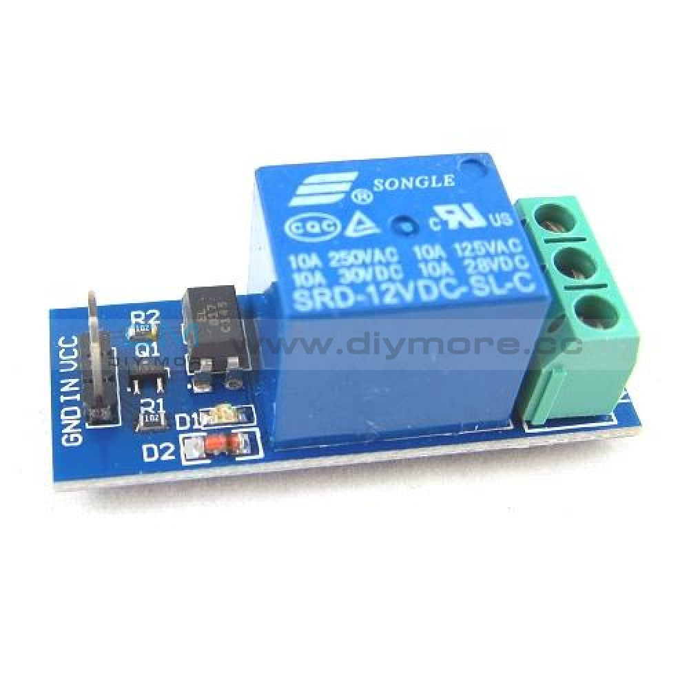
 Translation missing: en.products.product.regular_price $5.99{"id":4896534233159,"title":"DC 24V 4 Channel Relay Control Switch RS485\/TTL Anti-reverse Connection Module","handle":"dc-24v-4-channel-relay-control-switch-rs485-ttl-anti-reverse-connection-module","description":"\u003cdiv data-mce-fragment=\"1\"\u003e\u003cspan lang=\"en\" data-mce-fragment=\"1\"\u003e\u003cstrong data-mce-fragment=\"1\"\u003eOverview:\u003c\/strong\u003e\u003c\/span\u003e\u003c\/div\u003e\n\u003cdiv data-mce-fragment=\"1\"\u003e\n\u003cul\u003e\n\u003cli\u003e\u003cspan lang=\"en\" data-mce-fragment=\"1\"\u003eElsay four-way Modbus relay module is equipped with mature and stable 8-bit MCU and RS485 level communication chip. Using standard MODBUS RTU format RS485 communication protocol, it can realize 4 input signal detection and 4 relay output, which can be used for digital detection or power control occasions.\u003c\/span\u003e\u003c\/li\u003e\n\u003c\/ul\u003e\n\u003cspan lang=\"en\" data-mce-fragment=\"1\"\u003e\u003cspan lang=\"en\" data-mce-fragment=\"1\"\u003e\u003cstrong data-mce-fragment=\"1\"\u003eFeatures:\u003c\/strong\u003e\u003cbr data-mce-fragment=\"1\"\u003e\u003c\/span\u003e\u003c\/span\u003e\n\u003cul\u003e\n\u003cli\u003e\u003cspan lang=\"en\" data-mce-fragment=\"1\"\u003eOnboard mature and stable 8bit MCU and MAX485 level conversion chip;\u003c\/span\u003e\u003c\/li\u003e\n\u003cli\u003e\u003cspan lang=\"en\" data-mce-fragment=\"1\"\u003eCommunication protocol: support standard Modbus RTU protocol;\u003c\/span\u003e\u003c\/li\u003e\n\u003cli\u003e\u003cspan lang=\"en\" data-mce-fragment=\"1\"\u003eCommunication interface: support RS485\/TTL UART interface;\u003c\/span\u003e\u003c\/li\u003e\n\u003cli\u003e\u003cspan lang=\"en\" data-mce-fragment=\"1\"\u003eCommunication baud rate: 4800\/9600\/19200, the default is 9600bps, and it supports power-off save;\u003c\/span\u003e\u003c\/li\u003e\n\u003cli\u003e\u003cspan lang=\"en\" data-mce-fragment=\"1\"\u003eOptocoupler input signal range: DC3.3-30V (this input cannot be used for relay control);\u003c\/span\u003e\u003c\/li\u003e\n\u003cli\u003e\u003cspan lang=\"en\" data-mce-fragment=\"1\"\u003eOutput signal: relay switch signal, support manual, flash off, flash off mode, flash off\/flash off delay base is 0.1S, the maximum flash off\/flash off time can be set to 0xFFFF*0.1S=6553.5S;\u003c\/span\u003e\u003c\/li\u003e\n\u003cli\u003e\u003cspan lang=\"en\" data-mce-fragment=\"1\"\u003eDevice address: range 1-255, default 255, support power-off save;\u003c\/span\u003e\u003c\/li\u003e\n\u003cli\u003e\u003cspan lang=\"en\" data-mce-fragment=\"1\"\u003eThe baud rate, input signal, relay status, and device address can be read using software\/commands;\u003c\/span\u003e\u003c\/li\u003e\n\u003cli\u003e\u003cspan lang=\"en\" data-mce-fragment=\"1\"\u003eThere are 4 5V, 10A\/250V AC 10A\/30V DC relays on board, which can be activated continuously for 100,000 times, with diode effusion protection, and short response time;\u003c\/span\u003e\u003c\/li\u003e\n\u003cli\u003e\u003cspan lang=\"en\" data-mce-fragment=\"1\"\u003eOn-board relay switch indicator;\u003c\/span\u003e\u003c\/li\u003e\n\u003cli\u003e\u003cspan lang=\"en\" data-mce-fragment=\"1\"\u003ePower supply voltage: DC7-24V, support DC socket\/5.08mm terminal power supply, with input anti-reverse protection;\u003c\/span\u003e\u003c\/li\u003e\n\u003c\/ul\u003e\n\u003c\/div\u003e\n\u003cdiv data-mce-fragment=\"1\"\u003e\u003cspan data-mce-fragment=\"1\"\u003e\u003cstrong data-mce-fragment=\"1\"\u003e\u003cspan lang=\"en\" data-mce-fragment=\"1\"\u003e\u003cspan title=\"\" data-mce-fragment=\"1\"\u003eHardware introduction and description\u003c\/span\u003e\u003c\/span\u003e\u003c\/strong\u003e\u003c\/span\u003e\u003c\/div\u003e\n\u003cdiv data-mce-fragment=\"1\"\u003e\u003cspan lang=\"en\" data-mce-fragment=\"1\"\u003e\u003cspan title=\"\" data-mce-fragment=\"1\"\u003eBoard size\u003c\/span\u003e\u003c\/span\u003e\u003c\/div\u003e\n\u003cdiv data-mce-fragment=\"1\"\u003e\u003cspan lang=\"en\" data-mce-fragment=\"1\"\u003e\u003cspan title=\"\" data-mce-fragment=\"1\"\u003e\u003cimg src=\"https:\/\/pg-cdn-a2.datacaciques.com\/00\/NDAy\/20\/10\/27\/759miw180130a6g1\/f50580d1c231c450.jpg\" data-mce-fragment=\"1\" data-mce-src=\"https:\/\/pg-cdn-a2.datacaciques.com\/00\/NDAy\/20\/10\/27\/759miw180130a6g1\/f50580d1c231c450.jpg\"\u003e\u003c\/span\u003e\u003c\/span\u003e\u003c\/div\u003e\n\u003cdiv data-mce-fragment=\"1\"\u003e\u003cspan lang=\"en\" data-mce-fragment=\"1\"\u003e\u003cspan title=\"\" data-mce-fragment=\"1\"\u003eInterface introduction\u003c\/span\u003e\u003c\/span\u003e\u003c\/div\u003e\n\u003cdiv data-mce-fragment=\"1\"\u003e\u003cspan lang=\"en\" data-mce-fragment=\"1\"\u003e\u003cspan title=\"\" data-mce-fragment=\"1\"\u003e\u003cimg src=\"https:\/\/pg-cdn-a2.datacaciques.com\/00\/NDAy\/20\/10\/27\/759miw180130a6g1\/4bc7a5d2ad0c45a2.jpg\" data-mce-fragment=\"1\" data-mce-src=\"https:\/\/pg-cdn-a2.datacaciques.com\/00\/NDAy\/20\/10\/27\/759miw180130a6g1\/4bc7a5d2ad0c45a2.jpg\"\u003e\u003c\/span\u003e\u003c\/span\u003e\u003c\/div\u003e\n\u003cdiv data-mce-fragment=\"1\"\u003e\n\u003cul\u003e\n\u003cli\u003e\u003cspan lang=\"en\" data-mce-fragment=\"1\"\u003e\u003cspan title=\"\" data-mce-fragment=\"1\"\u003eDC-005 socket: DC7-24V power input socket;\u003c\/span\u003e\u003c\/span\u003e\u003c\/li\u003e\n\u003cli\u003e\u003cspan lang=\"en\" data-mce-fragment=\"1\"\u003e\u003cspan title=\"\" data-mce-fragment=\"1\"\u003eVCC, GND: DC7-24V 5.08mm power input terminal;\u003c\/span\u003e\u003c\/span\u003e\u003c\/li\u003e\n\u003cli\u003e\u003cspan lang=\"en\" data-mce-fragment=\"1\"\u003e\u003cspan title=\"\" data-mce-fragment=\"1\"\u003eDC3.3-30V optocoupler signal input:\u003c\/span\u003e\u003c\/span\u003e\u003c\/li\u003e\n\u003cli\u003e\u003cspan lang=\"en\" data-mce-fragment=\"1\"\u003e\u003cspan title=\"\" data-mce-fragment=\"1\"\u003eIN1: Channel 1 positive\u003c\/span\u003e\u003c\/span\u003e\u003c\/li\u003e\n\u003cli\u003e\u003cspan lang=\"en\" data-mce-fragment=\"1\"\u003e\u003cspan title=\"\" data-mce-fragment=\"1\"\u003eIN2: Channel 2 positive\u003c\/span\u003e\u003c\/span\u003e\u003c\/li\u003e\n\u003cli\u003e\u003cspan lang=\"en\" data-mce-fragment=\"1\"\u003e\u003cspan title=\"\" data-mce-fragment=\"1\"\u003eIN3: Channel 3 positive\u003c\/span\u003e\u003c\/span\u003e\u003c\/li\u003e\n\u003cli\u003e\u003cspan lang=\"en\" data-mce-fragment=\"1\"\u003e\u003cspan title=\"\" data-mce-fragment=\"1\"\u003eIN4: Channel 4 positive\u003c\/span\u003e\u003c\/span\u003e\u003c\/li\u003e\n\u003cli\u003e\u003cspan lang=\"en\" data-mce-fragment=\"1\"\u003e\u003cspan title=\"\" data-mce-fragment=\"1\"\u003eGND_IN: Common terminal negative\u003c\/span\u003e\u003c\/span\u003e\u003c\/li\u003e\n\u003cli\u003e\u003cspan lang=\"en\" data-mce-fragment=\"1\"\u003e\u003cspan title=\"\" data-mce-fragment=\"1\"\u003eA+, B-: RS485 communication interface, A+, B- are respectively connected to A+, B- of the external control terminal;\u003c\/span\u003e\u003c\/span\u003e\u003c\/li\u003e\n\u003c\/ul\u003e\n\u003cspan lang=\"en\" data-mce-fragment=\"1\"\u003e\u003cspan lang=\"en\" data-mce-fragment=\"1\"\u003e\u003cspan title=\"\" data-mce-fragment=\"1\"\u003e\u003cstrong\u003eRelay switch signal output:\u003c\/strong\u003e\u003cbr data-mce-fragment=\"1\"\u003e\u003c\/span\u003e\u003c\/span\u003e\u003c\/span\u003e\n\u003cul\u003e\n\u003cli\u003e\u003cspan lang=\"en\" data-mce-fragment=\"1\"\u003e\u003cspan title=\"\" data-mce-fragment=\"1\"\u003eNC: Normally closed terminal, the relay is short-connected with COM before it is closed, and it is suspended after it is closed;\u003c\/span\u003e\u003c\/span\u003e\u003c\/li\u003e\n\u003cli\u003e\u003cspan lang=\"en\" data-mce-fragment=\"1\"\u003e\u003cspan title=\"\" data-mce-fragment=\"1\"\u003eCOM: public end;\u003c\/span\u003e\u003c\/span\u003e\u003c\/li\u003e\n\u003cli\u003e\u003cspan lang=\"en\" data-mce-fragment=\"1\"\u003e\u003cspan title=\"\" data-mce-fragment=\"1\"\u003eNO: Normally open end, the relay is suspended before closing, and shorted to COM after closing.\u003c\/span\u003e\u003c\/span\u003e\u003c\/li\u003e\n\u003cli\u003e\u003cspan lang=\"en\" data-mce-fragment=\"1\"\u003e\u003cspan title=\"\" data-mce-fragment=\"1\"\u003e6, GND, RXD, TXD: TTL level UART communication interface, GND, RXD, TXD are respectively connected to GND, TXD, RXD of the external control terminal;\u003c\/span\u003e\u003c\/span\u003e\u003c\/li\u003e\n\u003c\/ul\u003e\n\u003c\/div\u003e\n\u003cdiv data-mce-fragment=\"1\"\u003e\n\u003cspan lang=\"en\" data-mce-fragment=\"1\"\u003e\u003cspan lang=\"en\" data-mce-fragment=\"1\"\u003e\u003cspan title=\"\" data-mce-fragment=\"1\"\u003e\u003cstrong data-mce-fragment=\"1\"\u003eProduct Parameters:\u003c\/strong\u003e\u003cbr data-mce-fragment=\"1\"\u003e\u003c\/span\u003e\u003c\/span\u003e\u003c\/span\u003e\n\u003cul\u003e\n\u003cli\u003e\u003cspan lang=\"en\" data-mce-fragment=\"1\"\u003e\u003cspan title=\"\" data-mce-fragment=\"1\"\u003eItem name: 4CH Modbus Relay Module \u003c\/span\u003e\u003c\/span\u003e\u003c\/li\u003e\n\u003cli\u003e\u003cspan lang=\"en\" data-mce-fragment=\"1\"\u003e\u003cspan title=\"\" data-mce-fragment=\"1\"\u003eWork voltage:DC 7V~24V\u003c\/span\u003e\u003c\/span\u003e\u003c\/li\u003e\n\u003cli\u003e\u003cspan lang=\"en\" data-mce-fragment=\"1\"\u003e\u003cspan title=\"\" data-mce-fragment=\"1\"\u003eBaud rate:4800\/9600\/19600bps(default 9600bps)\u003c\/span\u003e\u003c\/span\u003e\u003c\/li\u003e\n\u003cli\u003e\u003cspan lang=\"en\" data-mce-fragment=\"1\"\u003e\u003cspan title=\"\" data-mce-fragment=\"1\"\u003eOptocoupler input signal:DC 3.3V~30V\u003c\/span\u003e\u003c\/span\u003e\u003c\/li\u003e\n\u003cli\u003e\u003cspan lang=\"en\" data-mce-fragment=\"1\"\u003e\u003cspan title=\"\" data-mce-fragment=\"1\"\u003eSet address:1~255\u003c\/span\u003e\u003c\/span\u003e\u003c\/li\u003e\n\u003cli\u003e\u003cspan lang=\"en\" data-mce-fragment=\"1\"\u003e\u003cspan title=\"\" data-mce-fragment=\"1\"\u003eRelay contorl mode: ON\/OFF,Delay_ON,Delay_OFF mode\u003c\/span\u003e\u003c\/span\u003e\u003c\/li\u003e\n\u003cli\u003e\u003cspan lang=\"en\" data-mce-fragment=\"1\"\u003e\u003cspan title=\"\" data-mce-fragment=\"1\"\u003eDelay time: 0~6553.5s \u003c\/span\u003e\u003c\/span\u003e\u003c\/li\u003e\n\u003cli\u003e\u003cspan lang=\"en\" data-mce-fragment=\"1\"\u003e\u003cspan title=\"\" data-mce-fragment=\"1\"\u003eLoad: AC 250V 10A or DC 28V 10A\u003c\/span\u003e\u003c\/span\u003e\u003c\/li\u003e\n\u003cli\u003e\u003cspan lang=\"en\" data-mce-fragment=\"1\"\u003e\u003cspan title=\"\" data-mce-fragment=\"1\"\u003eProtocol:Modbus RTU\u003c\/span\u003e\u003c\/span\u003e\u003c\/li\u003e\n\u003cli\u003e\u003cspan lang=\"en\" data-mce-fragment=\"1\"\u003e\u003cspan title=\"\" data-mce-fragment=\"1\"\u003eInterface:RS485\/TTL UART\u003c\/span\u003e\u003c\/span\u003e\u003c\/li\u003e\n\u003cli\u003e\u003cspan lang=\"en\" data-mce-fragment=\"1\"\u003e\u003cspan title=\"\" data-mce-fragment=\"1\"\u003eControl channel: 4channel\u003c\/span\u003e\u003c\/span\u003e\u003c\/li\u003e\n\u003cli\u003e\u003cspan lang=\"en\" data-mce-fragment=\"1\"\u003e\u003cspan title=\"\" data-mce-fragment=\"1\"\u003eOperating Temperature:-20℃~85℃\u003c\/span\u003e\u003c\/span\u003e\u003c\/li\u003e\n\u003cli\u003e\u003cspan lang=\"en\" data-mce-fragment=\"1\"\u003e\u003cspan title=\"\" data-mce-fragment=\"1\"\u003eOperating Humidity:5%~95%RH\u003c\/span\u003e\u003c\/span\u003e\u003c\/li\u003e\n\u003cli\u003e\u003cspan lang=\"en\" data-mce-fragment=\"1\"\u003e\u003cspan title=\"\" data-mce-fragment=\"1\"\u003eModule Size:93*90*20mm\u003c\/span\u003e\u003c\/span\u003e\u003c\/li\u003e\n\u003c\/ul\u003e\n\u003cspan lang=\"en\" data-mce-fragment=\"1\"\u003e\u003cspan lang=\"en\" data-mce-fragment=\"1\"\u003e\u003cspan title=\"\" data-mce-fragment=\"1\"\u003e\u003cimg src=\"https:\/\/pg-cdn-a2.datacaciques.com\/00\/NDAy\/20\/10\/27\/759miw180130a6g1\/5a40dd1349231871.jpg\" data-mce-fragment=\"1\" data-mce-src=\"https:\/\/pg-cdn-a2.datacaciques.com\/00\/NDAy\/20\/10\/27\/759miw180130a6g1\/5a40dd1349231871.jpg\"\u003e\u003cbr data-mce-fragment=\"1\"\u003e\u003cstrong data-mce-fragment=\"1\"\u003eModbus RTU Command:\u003c\/strong\u003e\u003cbr data-mce-fragment=\"1\"\u003e\u003c\/span\u003e\u003c\/span\u003e\u003c\/span\u003e\n\u003cul\u003e\n\u003cli\u003e\u003cspan lang=\"en\" data-mce-fragment=\"1\"\u003e\u003cspan title=\"\" data-mce-fragment=\"1\"\u003eSuppose the device address is 0xFF so return 00 10 00 00 00 01 02 00 FF EB 80 and the 9th btye is device address.\u003c\/span\u003e\u003c\/span\u003e\u003c\/li\u003e\n\u003cli\u003e\u003cspan lang=\"en\" data-mce-fragment=\"1\"\u003e\u003cspan title=\"\" data-mce-fragment=\"1\"\u003eTurn ON CH_1 Relay(Normal Mode):\u003c\/span\u003e\u003c\/span\u003e\u003c\/li\u003e\n\u003cli\u003e\u003cspan lang=\"en\" data-mce-fragment=\"1\"\u003e\u003cspan title=\"\" data-mce-fragment=\"1\"\u003e Send: FF 05 00 00 FF 00 99 E4\u003c\/span\u003e\u003c\/span\u003e\u003c\/li\u003e\n\u003cli\u003e\u003cspan lang=\"en\" data-mce-fragment=\"1\"\u003e\u003cspan title=\"\" data-mce-fragment=\"1\"\u003e Return: FF 05 00 00 FF 00 99 E4\u003c\/span\u003e\u003c\/span\u003e\u003c\/li\u003e\n\u003cli\u003e\u003cspan lang=\"en\" data-mce-fragment=\"1\"\u003e\u003cspan title=\"\" data-mce-fragment=\"1\"\u003e Note_1:The 3rd and 4th byte are relay addresses.So it can be 0x0000,0x0001,0x0002,0x0003.\u003c\/span\u003e\u003c\/span\u003e\u003c\/li\u003e\n\u003cli\u003e\u003cspan lang=\"en\" data-mce-fragment=\"1\"\u003e\u003cspan title=\"\" data-mce-fragment=\"1\"\u003e Note_2:The 5th and 6th byte are relay data.0xFF00 means turn ON relay and 0x0000 means turn OFF relay.\u003c\/span\u003e\u003c\/span\u003e\u003c\/li\u003e\n\u003cli\u003e\u003cspan lang=\"en\" data-mce-fragment=\"1\"\u003e\u003cspan title=\"\" data-mce-fragment=\"1\"\u003eTurn OFF CH_1 Relay(Normal Mode):\u003c\/span\u003e\u003c\/span\u003e\u003c\/li\u003e\n\u003cli\u003e\u003cspan lang=\"en\" data-mce-fragment=\"1\"\u003e\u003cspan title=\"\" data-mce-fragment=\"1\"\u003e Send: FF 05 00 00 00 00 D8 14\u003c\/span\u003e\u003c\/span\u003e\u003c\/li\u003e\n\u003cli\u003e\u003cspan lang=\"en\" data-mce-fragment=\"1\"\u003e\u003cspan title=\"\" data-mce-fragment=\"1\"\u003e Return: FF 05 00 00 00 00 D8 14\u003c\/span\u003e\u003c\/span\u003e\u003c\/li\u003e\n\u003cli\u003e\u003cspan lang=\"en\" data-mce-fragment=\"1\"\u003e\u003cspan title=\"\" data-mce-fragment=\"1\"\u003eTurn ON CH_2 Relay(Normal Mode):\u003c\/span\u003e\u003c\/span\u003e\u003c\/li\u003e\n\u003cli\u003e\u003cspan lang=\"en\" data-mce-fragment=\"1\"\u003e\u003cspan title=\"\" data-mce-fragment=\"1\"\u003e Send: FF 05 00 01 FF 00 C8 24\u003c\/span\u003e\u003c\/span\u003e\u003c\/li\u003e\n\u003cli\u003e\u003cspan lang=\"en\" data-mce-fragment=\"1\"\u003e\u003cspan title=\"\" data-mce-fragment=\"1\"\u003e Return: FF 05 00 01 FF 00 C8 24\u003c\/span\u003e\u003c\/span\u003e\u003c\/li\u003e\n\u003cli\u003e\u003cspan lang=\"en\" data-mce-fragment=\"1\"\u003e\u003cspan title=\"\" data-mce-fragment=\"1\"\u003eTurn OFF CH_2 Relay(Normal Mode):\u003c\/span\u003e\u003c\/span\u003e\u003c\/li\u003e\n\u003cli\u003e\u003cspan lang=\"en\" data-mce-fragment=\"1\"\u003e\u003cspan title=\"\" data-mce-fragment=\"1\"\u003e Send: FF 05 00 01 00 00 89 D4\u003c\/span\u003e\u003c\/span\u003e\u003c\/li\u003e\n\u003cli\u003e\u003cspan lang=\"en\" data-mce-fragment=\"1\"\u003e\u003cspan title=\"\" data-mce-fragment=\"1\"\u003e Return: FF 05 00 01 00 00 89 D4\u003c\/span\u003e\u003c\/span\u003e\u003c\/li\u003e\n\u003cli\u003e\u003cspan lang=\"en\" data-mce-fragment=\"1\"\u003e\u003cspan title=\"\" data-mce-fragment=\"1\"\u003eTurn ON All relays:\u003c\/span\u003e\u003c\/span\u003e\u003c\/li\u003e\n\u003cli\u003e\u003cspan lang=\"en\" data-mce-fragment=\"1\"\u003e\u003cspan title=\"\" data-mce-fragment=\"1\"\u003e Send: FF 0F 00 00 00 08 01 FF 30 1D\u003c\/span\u003e\u003c\/span\u003e\u003c\/li\u003e\n\u003cli\u003e\u003cspan lang=\"en\" data-mce-fragment=\"1\"\u003e\u003cspan title=\"\" data-mce-fragment=\"1\"\u003e Return: FF 0F 00 00 00 08 41 D3\u003c\/span\u003e\u003c\/span\u003e\u003c\/li\u003e\n\u003cli\u003e\u003cspan lang=\"en\" data-mce-fragment=\"1\"\u003e\u003cspan title=\"\" data-mce-fragment=\"1\"\u003eTurn OFF All relays:\u003c\/span\u003e\u003c\/span\u003e\u003c\/li\u003e\n\u003cli\u003e\u003cspan lang=\"en\" data-mce-fragment=\"1\"\u003e\u003cspan title=\"\" data-mce-fragment=\"1\"\u003e Send: FF 0F 00 00 00 08 01 00 70 5D\u003c\/span\u003e\u003c\/span\u003e\u003c\/li\u003e\n\u003cli\u003e\u003cspan lang=\"en\" data-mce-fragment=\"1\"\u003e\u003cspan title=\"\" data-mce-fragment=\"1\"\u003e Return: FF 0F 00 00 00 08 41 D3\u003c\/span\u003e\u003c\/span\u003e\u003c\/li\u003e\n\u003cli\u003e\u003cspan lang=\"en\" data-mce-fragment=\"1\"\u003e\u003cspan title=\"\" data-mce-fragment=\"1\"\u003eSet device address to 0x01:\u003c\/span\u003e\u003c\/span\u003e\u003c\/li\u003e\n\u003cli\u003e\u003cspan lang=\"en\" data-mce-fragment=\"1\"\u003e\u003cspan title=\"\" data-mce-fragment=\"1\"\u003e Send: 00 10 00 00 00 01 02 00 01 6A 00\u003c\/span\u003e\u003c\/span\u003e\u003c\/li\u003e\n\u003cli\u003e\u003cspan lang=\"en\" data-mce-fragment=\"1\"\u003e\u003cspan title=\"\" data-mce-fragment=\"1\"\u003e Return: 00 10 00 00 00 01 02 00 01 6A 00\u003c\/span\u003e\u003c\/span\u003e\u003c\/li\u003e\n\u003cli\u003e\u003cspan lang=\"en\" data-mce-fragment=\"1\"\u003e\u003cspan title=\"\" data-mce-fragment=\"1\"\u003e Note: The 9th btye is device address.\u003c\/span\u003e\u003c\/span\u003e\u003c\/li\u003e\n\u003cli\u003e\u003cspan lang=\"en\" data-mce-fragment=\"1\"\u003e\u003cspan title=\"\" data-mce-fragment=\"1\"\u003eSet device address to 0xFF:\u003c\/span\u003e\u003c\/span\u003e\u003c\/li\u003e\n\u003cli\u003e\u003cspan lang=\"en\" data-mce-fragment=\"1\"\u003e\u003cspan title=\"\" data-mce-fragment=\"1\"\u003e Send: 00 10 00 00 00 01 02 00 FF EB 80\u003c\/span\u003e\u003c\/span\u003e\u003c\/li\u003e\n\u003cli\u003e\u003cspan lang=\"en\" data-mce-fragment=\"1\"\u003e\u003cspan title=\"\" data-mce-fragment=\"1\"\u003e Return: 00 10 00 00 00 01 02 00 FF EB 80\u003c\/span\u003e\u003c\/span\u003e\u003c\/li\u003e\n\u003cli\u003e\u003cspan lang=\"en\" data-mce-fragment=\"1\"\u003e\u003cspan title=\"\" data-mce-fragment=\"1\"\u003eRead device address:\u003c\/span\u003e\u003c\/span\u003e\u003c\/li\u003e\n\u003cli\u003e\u003cspan lang=\"en\" data-mce-fragment=\"1\"\u003e\u003cspan title=\"\" data-mce-fragment=\"1\"\u003e Send: 00 03 00 00 00 01 85 DB\u003c\/span\u003e\u003c\/span\u003e\u003c\/li\u003e\n\u003cli\u003e\u003cspan lang=\"en\" data-mce-fragment=\"1\"\u003e\u003cspan title=\"\" data-mce-fragment=\"1\"\u003e Return: 00 03 02 00 FF C5 C4\u003c\/span\u003e\u003c\/span\u003e\u003c\/li\u003e\n\u003cli\u003e\u003cspan lang=\"en\" data-mce-fragment=\"1\"\u003e\u003cspan title=\"\" data-mce-fragment=\"1\"\u003e Note: The 5th btye is device address.\u003c\/span\u003e\u003c\/span\u003e\u003c\/li\u003e\n\u003cli\u003e\u003cspan lang=\"en\" data-mce-fragment=\"1\"\u003e\u003cspan title=\"\" data-mce-fragment=\"1\"\u003eRead relay status:\u003c\/span\u003e\u003c\/span\u003e\u003c\/li\u003e\n\u003cli\u003e\u003cspan lang=\"en\" data-mce-fragment=\"1\"\u003e\u003cspan title=\"\" data-mce-fragment=\"1\"\u003e Send: FF 01 00 00 00 08 28 12\u003c\/span\u003e\u003c\/span\u003e\u003c\/li\u003e\n\u003cli\u003e\u003cspan lang=\"en\" data-mce-fragment=\"1\"\u003e\u003cspan title=\"\" data-mce-fragment=\"1\"\u003e Return: FF 01 01 01 A1 A0\u003c\/span\u003e\u003c\/span\u003e\u003c\/li\u003e\n\u003cli\u003e\u003cspan lang=\"en\" data-mce-fragment=\"1\"\u003e\u003cspan title=\"\" data-mce-fragment=\"1\"\u003e Note:The 4th means which one relay.0 means OFF and 1 means ON.\u003c\/span\u003e\u003c\/span\u003e\u003c\/li\u003e\n\u003cli\u003e\u003cspan lang=\"en\" data-mce-fragment=\"1\"\u003e\u003cspan title=\"\" data-mce-fragment=\"1\"\u003eRead optocoupler input staturs:\u003c\/span\u003e\u003c\/span\u003e\u003c\/li\u003e\n\u003cli\u003e\u003cspan lang=\"en\" data-mce-fragment=\"1\"\u003e\u003cspan title=\"\" data-mce-fragment=\"1\"\u003e Send: FF 02 00 00 00 08 6C 12\u003c\/span\u003e\u003c\/span\u003e\u003c\/li\u003e\n\u003cli\u003e\u003cspan lang=\"en\" data-mce-fragment=\"1\"\u003e\u003cspan title=\"\" data-mce-fragment=\"1\"\u003e Return: FF 02 01 01 51 A0\u003c\/span\u003e\u003c\/span\u003e\u003c\/li\u003e\n\u003cli\u003e\u003cspan lang=\"en\" data-mce-fragment=\"1\"\u003e\u003cspan title=\"\" data-mce-fragment=\"1\"\u003e Note:The 4th means which one input.0 means low level signal input and 1 means high level signal input.\u003c\/span\u003e\u003c\/span\u003e\u003c\/li\u003e\n\u003cli\u003e\u003cspan lang=\"en\" data-mce-fragment=\"1\"\u003e\u003cspan title=\"\" data-mce-fragment=\"1\"\u003eSet baud rate 4800bps:\u003c\/span\u003e\u003c\/span\u003e\u003c\/li\u003e\n\u003cli\u003e\u003cspan lang=\"en\" data-mce-fragment=\"1\"\u003e\u003cspan title=\"\" data-mce-fragment=\"1\"\u003e Send: FF 10 03 E9 00 01 02 00 02 4A 0C\u003c\/span\u003e\u003c\/span\u003e\u003c\/li\u003e\n\u003cli\u003e\u003cspan lang=\"en\" data-mce-fragment=\"1\"\u003e\u003cspan title=\"\" data-mce-fragment=\"1\"\u003e Return: FF 10 03 E9 00 01 C5 A7\u003c\/span\u003e\u003c\/span\u003e\u003c\/li\u003e\n\u003cli\u003e\u003cspan lang=\"en\" data-mce-fragment=\"1\"\u003e\u003cspan title=\"\" data-mce-fragment=\"1\"\u003e Note:The 9th btye is baud rate value.0x02 is 4800bps.0x03 is 9600bps.0x04 is 19200bps.\u003c\/span\u003e\u003c\/span\u003e\u003c\/li\u003e\n\u003cli\u003e\u003cspan lang=\"en\" data-mce-fragment=\"1\"\u003e\u003cspan title=\"\" data-mce-fragment=\"1\"\u003eSet baud rate 9600bps:\u003c\/span\u003e\u003c\/span\u003e\u003c\/li\u003e\n\u003cli\u003e\u003cspan lang=\"en\" data-mce-fragment=\"1\"\u003e\u003cspan title=\"\" data-mce-fragment=\"1\"\u003e Send: FF 10 03 E9 00 01 02 00 03 8B CC\u003c\/span\u003e\u003c\/span\u003e\u003c\/li\u003e\n\u003cli\u003e\u003cspan lang=\"en\" data-mce-fragment=\"1\"\u003e\u003cspan title=\"\" data-mce-fragment=\"1\"\u003e Return: FF 10 03 E9 00 01 C5 A7\u003c\/span\u003e\u003c\/span\u003e\u003c\/li\u003e\n\u003cli\u003e\u003cspan lang=\"en\" data-mce-fragment=\"1\"\u003e\u003cspan title=\"\" data-mce-fragment=\"1\"\u003eSet baud rate 19200bps:\u003c\/span\u003e\u003c\/span\u003e\u003c\/li\u003e\n\u003cli\u003e\u003cspan lang=\"en\" data-mce-fragment=\"1\"\u003e\u003cspan title=\"\" data-mce-fragment=\"1\"\u003e Send: FF 10 03 E9 00 01 02 00 04 CA 0E\u003c\/span\u003e\u003c\/span\u003e\u003c\/li\u003e\n\u003cli\u003e\u003cspan lang=\"en\" data-mce-fragment=\"1\"\u003e\u003cspan title=\"\" data-mce-fragment=\"1\"\u003e Return: FF 10 03 E9 00 01 C5 A7\u003c\/span\u003e\u003c\/span\u003e\u003c\/li\u003e\n\u003cli\u003e\u003cspan lang=\"en\" data-mce-fragment=\"1\"\u003e\u003cspan title=\"\" data-mce-fragment=\"1\"\u003eTurn ON CH_1 Relay(2S Flashing Mode):\u003c\/span\u003e\u003c\/span\u003e\u003c\/li\u003e\n\u003cli\u003e\u003cspan lang=\"en\" data-mce-fragment=\"1\"\u003e\u003cspan title=\"\" data-mce-fragment=\"1\"\u003e Send: FF 10 00 03 00 02 04 00 04 00 14 C5 9F\u003c\/span\u003e\u003c\/span\u003e\u003c\/li\u003e\n\u003cli\u003e\u003cspan lang=\"en\" data-mce-fragment=\"1\"\u003e\u003cspan title=\"\" data-mce-fragment=\"1\"\u003e Return: FF 10 00 03 00 02 A4 16\u003c\/span\u003e\u003c\/span\u003e\u003c\/li\u003e\n\u003cli\u003e\u003cspan lang=\"en\" data-mce-fragment=\"1\"\u003e\u003cspan title=\"\" data-mce-fragment=\"1\"\u003e Note_1:The 3rd and 4th byte are relay addresses.So CH1~CH4 can be 0x0003,0x0008,0x000D,0x0012.\u003c\/span\u003e\u003c\/span\u003e\u003c\/li\u003e\n\u003cli\u003e\u003cspan lang=\"en\" data-mce-fragment=\"1\"\u003e\u003cspan title=\"\" data-mce-fragment=\"1\"\u003e Note_2:The 10th and 11th byte are delay time in second.The minimum delay time is 0.1s.Relay will OFF after delay time.So the delay time in this command is : 0x0014*0.1=2S.\u003c\/span\u003e\u003c\/span\u003e\u003c\/li\u003e\n\u003cli\u003e\u003cspan lang=\"en\" data-mce-fragment=\"1\"\u003e\u003cspan title=\"\" data-mce-fragment=\"1\"\u003eTurn OFF CH_1 Relay(3S Flashing Mode):\u003c\/span\u003e\u003c\/span\u003e\u003c\/li\u003e\n\u003cli\u003e\u003cspan lang=\"en\" data-mce-fragment=\"1\"\u003e\u003cspan title=\"\" data-mce-fragment=\"1\"\u003e Send: FF 10 00 03 00 02 04 00 02 00 1E A5 99\u003c\/span\u003e\u003c\/span\u003e\u003c\/li\u003e\n\u003cli\u003e\u003cspan lang=\"en\" data-mce-fragment=\"1\"\u003e\u003cspan title=\"\" data-mce-fragment=\"1\"\u003e Return: FF 10 00 03 00 02 A4 16\u003c\/span\u003e\u003c\/span\u003e\u003c\/li\u003e\n\u003cli\u003e\u003cspan lang=\"en\" data-mce-fragment=\"1\"\u003e\u003cspan title=\"\" data-mce-fragment=\"1\"\u003e Note:Relay will ON after delay time.So the delay time in this command is : 0x001E*0.1=3S.\u003c\/span\u003e\u003c\/span\u003e\u003c\/li\u003e\n\u003c\/ul\u003e\n\u003cspan lang=\"en\" data-mce-fragment=\"1\"\u003e\u003cspan lang=\"en\" data-mce-fragment=\"1\"\u003e\u003cspan title=\"\" data-mce-fragment=\"1\"\u003e\u003cimg src=\"https:\/\/pg-cdn-a2.datacaciques.com\/00\/NDAy\/20\/10\/27\/759miw180130a6g1\/b4e1c2017abb1ec6.jpg\" data-mce-fragment=\"1\" data-mce-src=\"https:\/\/pg-cdn-a2.datacaciques.com\/00\/NDAy\/20\/10\/27\/759miw180130a6g1\/b4e1c2017abb1ec6.jpg\"\u003e\u003cbr data-mce-fragment=\"1\"\u003e\u003cstrong data-mce-fragment=\"1\"\u003ePackage Include:\u003c\/strong\u003e\u003cbr data-mce-fragment=\"1\"\u003e\u003c\/span\u003e\u003c\/span\u003e\u003c\/span\u003e\n\u003cul\u003e\n\u003cli\u003e\u003cspan lang=\"en\" data-mce-fragment=\"1\"\u003e\u003cspan title=\"\" data-mce-fragment=\"1\"\u003e 1PC 4CH Modbus Relay Module \u003c\/span\u003e\u003c\/span\u003e\u003c\/li\u003e\n\u003c\/ul\u003e\n\u003c\/div\u003e\n\u003cdiv data-mce-fragment=\"1\"\u003e\u003cspan lang=\"en\" data-mce-fragment=\"1\"\u003e\u003cspan title=\"\" data-mce-fragment=\"1\"\u003e \u003c\/span\u003e\u003c\/span\u003e\u003c\/div\u003e","published_at":"2020-10-29T16:43:18+08:00","created_at":"2020-10-28T12:04:09+08:00","vendor":"DIYMORE","type":"","tags":[],"price":1099,"price_min":1099,"price_max":1099,"available":true,"price_varies":false,"compare_at_price":null,"compare_at_price_min":0,"compare_at_price_max":0,"compare_at_price_varies":false,"variants":[{"id":32644275765319,"title":"Default Title","option1":"Default Title","option2":null,"option3":null,"sku":"XM0006","requires_shipping":true,"taxable":false,"featured_image":null,"available":true,"name":"DC 24V 4 Channel Relay Control Switch RS485\/TTL Anti-reverse Connection Module","public_title":null,"options":["Default Title"],"price":1099,"weight":0,"compare_at_price":null,"inventory_management":"shopify","barcode":"","requires_selling_plan":false,"selling_plan_allocations":[],"quantity_rule":{"min":1,"max":null,"increment":1}}],"images":["\/\/www.diymore.cc\/cdn\/shop\/products\/3_c1c2716b-4e56-4778-96d4-eb4ff9c7620a.jpg?v=1603857853","\/\/www.diymore.cc\/cdn\/shop\/products\/5_ff208254-a902-4d04-93e4-bce5ea8eb512.jpg?v=1603857854","\/\/www.diymore.cc\/cdn\/shop\/products\/4_0b281e6a-ef90-4366-8a24-d9a167cf31ca.jpg?v=1603857854","\/\/www.diymore.cc\/cdn\/shop\/products\/1_968bb946-a0f2-4ed7-8618-2ab8b7fa26f9.jpg?v=1603857854","\/\/www.diymore.cc\/cdn\/shop\/products\/2_5f6abbf8-5697-4e69-9c60-03559cfb6029.jpg?v=1603857854"],"featured_image":"\/\/www.diymore.cc\/cdn\/shop\/products\/3_c1c2716b-4e56-4778-96d4-eb4ff9c7620a.jpg?v=1603857853","options":["Title"],"media":[{"alt":null,"id":7652174987335,"position":1,"preview_image":{"aspect_ratio":1.0,"height":1000,"width":1000,"src":"\/\/www.diymore.cc\/cdn\/shop\/products\/3_c1c2716b-4e56-4778-96d4-eb4ff9c7620a.jpg?v=1603857853"},"aspect_ratio":1.0,"height":1000,"media_type":"image","src":"\/\/www.diymore.cc\/cdn\/shop\/products\/3_c1c2716b-4e56-4778-96d4-eb4ff9c7620a.jpg?v=1603857853","width":1000},{"alt":null,"id":7652175020103,"position":2,"preview_image":{"aspect_ratio":1.0,"height":1000,"width":1000,"src":"\/\/www.diymore.cc\/cdn\/shop\/products\/5_ff208254-a902-4d04-93e4-bce5ea8eb512.jpg?v=1603857854"},"aspect_ratio":1.0,"height":1000,"media_type":"image","src":"\/\/www.diymore.cc\/cdn\/shop\/products\/5_ff208254-a902-4d04-93e4-bce5ea8eb512.jpg?v=1603857854","width":1000},{"alt":null,"id":7652175052871,"position":3,"preview_image":{"aspect_ratio":1.0,"height":1000,"width":1000,"src":"\/\/www.diymore.cc\/cdn\/shop\/products\/4_0b281e6a-ef90-4366-8a24-d9a167cf31ca.jpg?v=1603857854"},"aspect_ratio":1.0,"height":1000,"media_type":"image","src":"\/\/www.diymore.cc\/cdn\/shop\/products\/4_0b281e6a-ef90-4366-8a24-d9a167cf31ca.jpg?v=1603857854","width":1000},{"alt":null,"id":7652175085639,"position":4,"preview_image":{"aspect_ratio":1.0,"height":1000,"width":1000,"src":"\/\/www.diymore.cc\/cdn\/shop\/products\/1_968bb946-a0f2-4ed7-8618-2ab8b7fa26f9.jpg?v=1603857854"},"aspect_ratio":1.0,"height":1000,"media_type":"image","src":"\/\/www.diymore.cc\/cdn\/shop\/products\/1_968bb946-a0f2-4ed7-8618-2ab8b7fa26f9.jpg?v=1603857854","width":1000},{"alt":null,"id":7652175118407,"position":5,"preview_image":{"aspect_ratio":1.0,"height":1000,"width":1000,"src":"\/\/www.diymore.cc\/cdn\/shop\/products\/2_5f6abbf8-5697-4e69-9c60-03559cfb6029.jpg?v=1603857854"},"aspect_ratio":1.0,"height":1000,"media_type":"image","src":"\/\/www.diymore.cc\/cdn\/shop\/products\/2_5f6abbf8-5697-4e69-9c60-03559cfb6029.jpg?v=1603857854","width":1000}],"requires_selling_plan":false,"selling_plan_groups":[],"content":"\u003cdiv data-mce-fragment=\"1\"\u003e\u003cspan lang=\"en\" data-mce-fragment=\"1\"\u003e\u003cstrong data-mce-fragment=\"1\"\u003eOverview:\u003c\/strong\u003e\u003c\/span\u003e\u003c\/div\u003e\n\u003cdiv data-mce-fragment=\"1\"\u003e\n\u003cul\u003e\n\u003cli\u003e\u003cspan lang=\"en\" data-mce-fragment=\"1\"\u003eElsay four-way Modbus relay module is equipped with mature and stable 8-bit MCU and RS485 level communication chip. Using standard MODBUS RTU format RS485 communication protocol, it can realize 4 input signal detection and 4 relay output, which can be used for digital detection or power control occasions.\u003c\/span\u003e\u003c\/li\u003e\n\u003c\/ul\u003e\n\u003cspan lang=\"en\" data-mce-fragment=\"1\"\u003e\u003cspan lang=\"en\" data-mce-fragment=\"1\"\u003e\u003cstrong data-mce-fragment=\"1\"\u003eFeatures:\u003c\/strong\u003e\u003cbr data-mce-fragment=\"1\"\u003e\u003c\/span\u003e\u003c\/span\u003e\n\u003cul\u003e\n\u003cli\u003e\u003cspan lang=\"en\" data-mce-fragment=\"1\"\u003eOnboard mature and stable 8bit MCU and MAX485 level conversion chip;\u003c\/span\u003e\u003c\/li\u003e\n\u003cli\u003e\u003cspan lang=\"en\" data-mce-fragment=\"1\"\u003eCommunication protocol: support standard Modbus RTU protocol;\u003c\/span\u003e\u003c\/li\u003e\n\u003cli\u003e\u003cspan lang=\"en\" data-mce-fragment=\"1\"\u003eCommunication interface: support RS485\/TTL UART interface;\u003c\/span\u003e\u003c\/li\u003e\n\u003cli\u003e\u003cspan lang=\"en\" data-mce-fragment=\"1\"\u003eCommunication baud rate: 4800\/9600\/19200, the default is 9600bps, and it supports power-off save;\u003c\/span\u003e\u003c\/li\u003e\n\u003cli\u003e\u003cspan lang=\"en\" data-mce-fragment=\"1\"\u003eOptocoupler input signal range: DC3.3-30V (this input cannot be used for relay control);\u003c\/span\u003e\u003c\/li\u003e\n\u003cli\u003e\u003cspan lang=\"en\" data-mce-fragment=\"1\"\u003eOutput signal: relay switch signal, support manual, flash off, flash off mode, flash off\/flash off delay base is 0.1S, the maximum flash off\/flash off time can be set to 0xFFFF*0.1S=6553.5S;\u003c\/span\u003e\u003c\/li\u003e\n\u003cli\u003e\u003cspan lang=\"en\" data-mce-fragment=\"1\"\u003eDevice address: range 1-255, default 255, support power-off save;\u003c\/span\u003e\u003c\/li\u003e\n\u003cli\u003e\u003cspan lang=\"en\" data-mce-fragment=\"1\"\u003eThe baud rate, input signal, relay status, and device address can be read using software\/commands;\u003c\/span\u003e\u003c\/li\u003e\n\u003cli\u003e\u003cspan lang=\"en\" data-mce-fragment=\"1\"\u003eThere are 4 5V, 10A\/250V AC 10A\/30V DC relays on board, which can be activated continuously for 100,000 times, with diode effusion protection, and short response time;\u003c\/span\u003e\u003c\/li\u003e\n\u003cli\u003e\u003cspan lang=\"en\" data-mce-fragment=\"1\"\u003eOn-board relay switch indicator;\u003c\/span\u003e\u003c\/li\u003e\n\u003cli\u003e\u003cspan lang=\"en\" data-mce-fragment=\"1\"\u003ePower supply voltage: DC7-24V, support DC socket\/5.08mm terminal power supply, with input anti-reverse protection;\u003c\/span\u003e\u003c\/li\u003e\n\u003c\/ul\u003e\n\u003c\/div\u003e\n\u003cdiv data-mce-fragment=\"1\"\u003e\u003cspan data-mce-fragment=\"1\"\u003e\u003cstrong data-mce-fragment=\"1\"\u003e\u003cspan lang=\"en\" data-mce-fragment=\"1\"\u003e\u003cspan title=\"\" data-mce-fragment=\"1\"\u003eHardware introduction and description\u003c\/span\u003e\u003c\/span\u003e\u003c\/strong\u003e\u003c\/span\u003e\u003c\/div\u003e\n\u003cdiv data-mce-fragment=\"1\"\u003e\u003cspan lang=\"en\" data-mce-fragment=\"1\"\u003e\u003cspan title=\"\" data-mce-fragment=\"1\"\u003eBoard size\u003c\/span\u003e\u003c\/span\u003e\u003c\/div\u003e\n\u003cdiv data-mce-fragment=\"1\"\u003e\u003cspan lang=\"en\" data-mce-fragment=\"1\"\u003e\u003cspan title=\"\" data-mce-fragment=\"1\"\u003e\u003cimg src=\"https:\/\/pg-cdn-a2.datacaciques.com\/00\/NDAy\/20\/10\/27\/759miw180130a6g1\/f50580d1c231c450.jpg\" data-mce-fragment=\"1\" data-mce-src=\"https:\/\/pg-cdn-a2.datacaciques.com\/00\/NDAy\/20\/10\/27\/759miw180130a6g1\/f50580d1c231c450.jpg\"\u003e\u003c\/span\u003e\u003c\/span\u003e\u003c\/div\u003e\n\u003cdiv data-mce-fragment=\"1\"\u003e\u003cspan lang=\"en\" data-mce-fragment=\"1\"\u003e\u003cspan title=\"\" data-mce-fragment=\"1\"\u003eInterface introduction\u003c\/span\u003e\u003c\/span\u003e\u003c\/div\u003e\n\u003cdiv data-mce-fragment=\"1\"\u003e\u003cspan lang=\"en\" data-mce-fragment=\"1\"\u003e\u003cspan title=\"\" data-mce-fragment=\"1\"\u003e\u003cimg src=\"https:\/\/pg-cdn-a2.datacaciques.com\/00\/NDAy\/20\/10\/27\/759miw180130a6g1\/4bc7a5d2ad0c45a2.jpg\" data-mce-fragment=\"1\" data-mce-src=\"https:\/\/pg-cdn-a2.datacaciques.com\/00\/NDAy\/20\/10\/27\/759miw180130a6g1\/4bc7a5d2ad0c45a2.jpg\"\u003e\u003c\/span\u003e\u003c\/span\u003e\u003c\/div\u003e\n\u003cdiv data-mce-fragment=\"1\"\u003e\n\u003cul\u003e\n\u003cli\u003e\u003cspan lang=\"en\" data-mce-fragment=\"1\"\u003e\u003cspan title=\"\" data-mce-fragment=\"1\"\u003eDC-005 socket: DC7-24V power input socket;\u003c\/span\u003e\u003c\/span\u003e\u003c\/li\u003e\n\u003cli\u003e\u003cspan lang=\"en\" data-mce-fragment=\"1\"\u003e\u003cspan title=\"\" data-mce-fragment=\"1\"\u003eVCC, GND: DC7-24V 5.08mm power input terminal;\u003c\/span\u003e\u003c\/span\u003e\u003c\/li\u003e\n\u003cli\u003e\u003cspan lang=\"en\" data-mce-fragment=\"1\"\u003e\u003cspan title=\"\" data-mce-fragment=\"1\"\u003eDC3.3-30V optocoupler signal input:\u003c\/span\u003e\u003c\/span\u003e\u003c\/li\u003e\n\u003cli\u003e\u003cspan lang=\"en\" data-mce-fragment=\"1\"\u003e\u003cspan title=\"\" data-mce-fragment=\"1\"\u003eIN1: Channel 1 positive\u003c\/span\u003e\u003c\/span\u003e\u003c\/li\u003e\n\u003cli\u003e\u003cspan lang=\"en\" data-mce-fragment=\"1\"\u003e\u003cspan title=\"\" data-mce-fragment=\"1\"\u003eIN2: Channel 2 positive\u003c\/span\u003e\u003c\/span\u003e\u003c\/li\u003e\n\u003cli\u003e\u003cspan lang=\"en\" data-mce-fragment=\"1\"\u003e\u003cspan title=\"\" data-mce-fragment=\"1\"\u003eIN3: Channel 3 positive\u003c\/span\u003e\u003c\/span\u003e\u003c\/li\u003e\n\u003cli\u003e\u003cspan lang=\"en\" data-mce-fragment=\"1\"\u003e\u003cspan title=\"\" data-mce-fragment=\"1\"\u003eIN4: Channel 4 positive\u003c\/span\u003e\u003c\/span\u003e\u003c\/li\u003e\n\u003cli\u003e\u003cspan lang=\"en\" data-mce-fragment=\"1\"\u003e\u003cspan title=\"\" data-mce-fragment=\"1\"\u003eGND_IN: Common terminal negative\u003c\/span\u003e\u003c\/span\u003e\u003c\/li\u003e\n\u003cli\u003e\u003cspan lang=\"en\" data-mce-fragment=\"1\"\u003e\u003cspan title=\"\" data-mce-fragment=\"1\"\u003eA+, B-: RS485 communication interface, A+, B- are respectively connected to A+, B- of the external control terminal;\u003c\/span\u003e\u003c\/span\u003e\u003c\/li\u003e\n\u003c\/ul\u003e\n\u003cspan lang=\"en\" data-mce-fragment=\"1\"\u003e\u003cspan lang=\"en\" data-mce-fragment=\"1\"\u003e\u003cspan title=\"\" data-mce-fragment=\"1\"\u003e\u003cstrong\u003eRelay switch signal output:\u003c\/strong\u003e\u003cbr data-mce-fragment=\"1\"\u003e\u003c\/span\u003e\u003c\/span\u003e\u003c\/span\u003e\n\u003cul\u003e\n\u003cli\u003e\u003cspan lang=\"en\" data-mce-fragment=\"1\"\u003e\u003cspan title=\"\" data-mce-fragment=\"1\"\u003eNC: Normally closed terminal, the relay is short-connected with COM before it is closed, and it is suspended after it is closed;\u003c\/span\u003e\u003c\/span\u003e\u003c\/li\u003e\n\u003cli\u003e\u003cspan lang=\"en\" data-mce-fragment=\"1\"\u003e\u003cspan title=\"\" data-mce-fragment=\"1\"\u003eCOM: public end;\u003c\/span\u003e\u003c\/span\u003e\u003c\/li\u003e\n\u003cli\u003e\u003cspan lang=\"en\" data-mce-fragment=\"1\"\u003e\u003cspan title=\"\" data-mce-fragment=\"1\"\u003eNO: Normally open end, the relay is suspended before closing, and shorted to COM after closing.\u003c\/span\u003e\u003c\/span\u003e\u003c\/li\u003e\n\u003cli\u003e\u003cspan lang=\"en\" data-mce-fragment=\"1\"\u003e\u003cspan title=\"\" data-mce-fragment=\"1\"\u003e6, GND, RXD, TXD: TTL level UART communication interface, GND, RXD, TXD are respectively connected to GND, TXD, RXD of the external control terminal;\u003c\/span\u003e\u003c\/span\u003e\u003c\/li\u003e\n\u003c\/ul\u003e\n\u003c\/div\u003e\n\u003cdiv data-mce-fragment=\"1\"\u003e\n\u003cspan lang=\"en\" data-mce-fragment=\"1\"\u003e\u003cspan lang=\"en\" data-mce-fragment=\"1\"\u003e\u003cspan title=\"\" data-mce-fragment=\"1\"\u003e\u003cstrong data-mce-fragment=\"1\"\u003eProduct Parameters:\u003c\/strong\u003e\u003cbr data-mce-fragment=\"1\"\u003e\u003c\/span\u003e\u003c\/span\u003e\u003c\/span\u003e\n\u003cul\u003e\n\u003cli\u003e\u003cspan lang=\"en\" data-mce-fragment=\"1\"\u003e\u003cspan title=\"\" data-mce-fragment=\"1\"\u003eItem name: 4CH Modbus Relay Module \u003c\/span\u003e\u003c\/span\u003e\u003c\/li\u003e\n\u003cli\u003e\u003cspan lang=\"en\" data-mce-fragment=\"1\"\u003e\u003cspan title=\"\" data-mce-fragment=\"1\"\u003eWork voltage:DC 7V~24V\u003c\/span\u003e\u003c\/span\u003e\u003c\/li\u003e\n\u003cli\u003e\u003cspan lang=\"en\" data-mce-fragment=\"1\"\u003e\u003cspan title=\"\" data-mce-fragment=\"1\"\u003eBaud rate:4800\/9600\/19600bps(default 9600bps)\u003c\/span\u003e\u003c\/span\u003e\u003c\/li\u003e\n\u003cli\u003e\u003cspan lang=\"en\" data-mce-fragment=\"1\"\u003e\u003cspan title=\"\" data-mce-fragment=\"1\"\u003eOptocoupler input signal:DC 3.3V~30V\u003c\/span\u003e\u003c\/span\u003e\u003c\/li\u003e\n\u003cli\u003e\u003cspan lang=\"en\" data-mce-fragment=\"1\"\u003e\u003cspan title=\"\" data-mce-fragment=\"1\"\u003eSet address:1~255\u003c\/span\u003e\u003c\/span\u003e\u003c\/li\u003e\n\u003cli\u003e\u003cspan lang=\"en\" data-mce-fragment=\"1\"\u003e\u003cspan title=\"\" data-mce-fragment=\"1\"\u003eRelay contorl mode: ON\/OFF,Delay_ON,Delay_OFF mode\u003c\/span\u003e\u003c\/span\u003e\u003c\/li\u003e\n\u003cli\u003e\u003cspan lang=\"en\" data-mce-fragment=\"1\"\u003e\u003cspan title=\"\" data-mce-fragment=\"1\"\u003eDelay time: 0~6553.5s \u003c\/span\u003e\u003c\/span\u003e\u003c\/li\u003e\n\u003cli\u003e\u003cspan lang=\"en\" data-mce-fragment=\"1\"\u003e\u003cspan title=\"\" data-mce-fragment=\"1\"\u003eLoad: AC 250V 10A or DC 28V 10A\u003c\/span\u003e\u003c\/span\u003e\u003c\/li\u003e\n\u003cli\u003e\u003cspan lang=\"en\" data-mce-fragment=\"1\"\u003e\u003cspan title=\"\" data-mce-fragment=\"1\"\u003eProtocol:Modbus RTU\u003c\/span\u003e\u003c\/span\u003e\u003c\/li\u003e\n\u003cli\u003e\u003cspan lang=\"en\" data-mce-fragment=\"1\"\u003e\u003cspan title=\"\" data-mce-fragment=\"1\"\u003eInterface:RS485\/TTL UART\u003c\/span\u003e\u003c\/span\u003e\u003c\/li\u003e\n\u003cli\u003e\u003cspan lang=\"en\" data-mce-fragment=\"1\"\u003e\u003cspan title=\"\" data-mce-fragment=\"1\"\u003eControl channel: 4channel\u003c\/span\u003e\u003c\/span\u003e\u003c\/li\u003e\n\u003cli\u003e\u003cspan lang=\"en\" data-mce-fragment=\"1\"\u003e\u003cspan title=\"\" data-mce-fragment=\"1\"\u003eOperating Temperature:-20℃~85℃\u003c\/span\u003e\u003c\/span\u003e\u003c\/li\u003e\n\u003cli\u003e\u003cspan lang=\"en\" data-mce-fragment=\"1\"\u003e\u003cspan title=\"\" data-mce-fragment=\"1\"\u003eOperating Humidity:5%~95%RH\u003c\/span\u003e\u003c\/span\u003e\u003c\/li\u003e\n\u003cli\u003e\u003cspan lang=\"en\" data-mce-fragment=\"1\"\u003e\u003cspan title=\"\" data-mce-fragment=\"1\"\u003eModule Size:93*90*20mm\u003c\/span\u003e\u003c\/span\u003e\u003c\/li\u003e\n\u003c\/ul\u003e\n\u003cspan lang=\"en\" data-mce-fragment=\"1\"\u003e\u003cspan lang=\"en\" data-mce-fragment=\"1\"\u003e\u003cspan title=\"\" data-mce-fragment=\"1\"\u003e\u003cimg src=\"https:\/\/pg-cdn-a2.datacaciques.com\/00\/NDAy\/20\/10\/27\/759miw180130a6g1\/5a40dd1349231871.jpg\" data-mce-fragment=\"1\" data-mce-src=\"https:\/\/pg-cdn-a2.datacaciques.com\/00\/NDAy\/20\/10\/27\/759miw180130a6g1\/5a40dd1349231871.jpg\"\u003e\u003cbr data-mce-fragment=\"1\"\u003e\u003cstrong data-mce-fragment=\"1\"\u003eModbus RTU Command:\u003c\/strong\u003e\u003cbr data-mce-fragment=\"1\"\u003e\u003c\/span\u003e\u003c\/span\u003e\u003c\/span\u003e\n\u003cul\u003e\n\u003cli\u003e\u003cspan lang=\"en\" data-mce-fragment=\"1\"\u003e\u003cspan title=\"\" data-mce-fragment=\"1\"\u003eSuppose the device address is 0xFF so return 00 10 00 00 00 01 02 00 FF EB 80 and the 9th btye is device address.\u003c\/span\u003e\u003c\/span\u003e\u003c\/li\u003e\n\u003cli\u003e\u003cspan lang=\"en\" data-mce-fragment=\"1\"\u003e\u003cspan title=\"\" data-mce-fragment=\"1\"\u003eTurn ON CH_1 Relay(Normal Mode):\u003c\/span\u003e\u003c\/span\u003e\u003c\/li\u003e\n\u003cli\u003e\u003cspan lang=\"en\" data-mce-fragment=\"1\"\u003e\u003cspan title=\"\" data-mce-fragment=\"1\"\u003e Send: FF 05 00 00 FF 00 99 E4\u003c\/span\u003e\u003c\/span\u003e\u003c\/li\u003e\n\u003cli\u003e\u003cspan lang=\"en\" data-mce-fragment=\"1\"\u003e\u003cspan title=\"\" data-mce-fragment=\"1\"\u003e Return: FF 05 00 00 FF 00 99 E4\u003c\/span\u003e\u003c\/span\u003e\u003c\/li\u003e\n\u003cli\u003e\u003cspan lang=\"en\" data-mce-fragment=\"1\"\u003e\u003cspan title=\"\" data-mce-fragment=\"1\"\u003e Note_1:The 3rd and 4th byte are relay addresses.So it can be 0x0000,0x0001,0x0002,0x0003.\u003c\/span\u003e\u003c\/span\u003e\u003c\/li\u003e\n\u003cli\u003e\u003cspan lang=\"en\" data-mce-fragment=\"1\"\u003e\u003cspan title=\"\" data-mce-fragment=\"1\"\u003e Note_2:The 5th and 6th byte are relay data.0xFF00 means turn ON relay and 0x0000 means turn OFF relay.\u003c\/span\u003e\u003c\/span\u003e\u003c\/li\u003e\n\u003cli\u003e\u003cspan lang=\"en\" data-mce-fragment=\"1\"\u003e\u003cspan title=\"\" data-mce-fragment=\"1\"\u003eTurn OFF CH_1 Relay(Normal Mode):\u003c\/span\u003e\u003c\/span\u003e\u003c\/li\u003e\n\u003cli\u003e\u003cspan lang=\"en\" data-mce-fragment=\"1\"\u003e\u003cspan title=\"\" data-mce-fragment=\"1\"\u003e Send: FF 05 00 00 00 00 D8 14\u003c\/span\u003e\u003c\/span\u003e\u003c\/li\u003e\n\u003cli\u003e\u003cspan lang=\"en\" data-mce-fragment=\"1\"\u003e\u003cspan title=\"\" data-mce-fragment=\"1\"\u003e Return: FF 05 00 00 00 00 D8 14\u003c\/span\u003e\u003c\/span\u003e\u003c\/li\u003e\n\u003cli\u003e\u003cspan lang=\"en\" data-mce-fragment=\"1\"\u003e\u003cspan title=\"\" data-mce-fragment=\"1\"\u003eTurn ON CH_2 Relay(Normal Mode):\u003c\/span\u003e\u003c\/span\u003e\u003c\/li\u003e\n\u003cli\u003e\u003cspan lang=\"en\" data-mce-fragment=\"1\"\u003e\u003cspan title=\"\" data-mce-fragment=\"1\"\u003e Send: FF 05 00 01 FF 00 C8 24\u003c\/span\u003e\u003c\/span\u003e\u003c\/li\u003e\n\u003cli\u003e\u003cspan lang=\"en\" data-mce-fragment=\"1\"\u003e\u003cspan title=\"\" data-mce-fragment=\"1\"\u003e Return: FF 05 00 01 FF 00 C8 24\u003c\/span\u003e\u003c\/span\u003e\u003c\/li\u003e\n\u003cli\u003e\u003cspan lang=\"en\" data-mce-fragment=\"1\"\u003e\u003cspan title=\"\" data-mce-fragment=\"1\"\u003eTurn OFF CH_2 Relay(Normal Mode):\u003c\/span\u003e\u003c\/span\u003e\u003c\/li\u003e\n\u003cli\u003e\u003cspan lang=\"en\" data-mce-fragment=\"1\"\u003e\u003cspan title=\"\" data-mce-fragment=\"1\"\u003e Send: FF 05 00 01 00 00 89 D4\u003c\/span\u003e\u003c\/span\u003e\u003c\/li\u003e\n\u003cli\u003e\u003cspan lang=\"en\" data-mce-fragment=\"1\"\u003e\u003cspan title=\"\" data-mce-fragment=\"1\"\u003e Return: FF 05 00 01 00 00 89 D4\u003c\/span\u003e\u003c\/span\u003e\u003c\/li\u003e\n\u003cli\u003e\u003cspan lang=\"en\" data-mce-fragment=\"1\"\u003e\u003cspan title=\"\" data-mce-fragment=\"1\"\u003eTurn ON All relays:\u003c\/span\u003e\u003c\/span\u003e\u003c\/li\u003e\n\u003cli\u003e\u003cspan lang=\"en\" data-mce-fragment=\"1\"\u003e\u003cspan title=\"\" data-mce-fragment=\"1\"\u003e Send: FF 0F 00 00 00 08 01 FF 30 1D\u003c\/span\u003e\u003c\/span\u003e\u003c\/li\u003e\n\u003cli\u003e\u003cspan lang=\"en\" data-mce-fragment=\"1\"\u003e\u003cspan title=\"\" data-mce-fragment=\"1\"\u003e Return: FF 0F 00 00 00 08 41 D3\u003c\/span\u003e\u003c\/span\u003e\u003c\/li\u003e\n\u003cli\u003e\u003cspan lang=\"en\" data-mce-fragment=\"1\"\u003e\u003cspan title=\"\" data-mce-fragment=\"1\"\u003eTurn OFF All relays:\u003c\/span\u003e\u003c\/span\u003e\u003c\/li\u003e\n\u003cli\u003e\u003cspan lang=\"en\" data-mce-fragment=\"1\"\u003e\u003cspan title=\"\" data-mce-fragment=\"1\"\u003e Send: FF 0F 00 00 00 08 01 00 70 5D\u003c\/span\u003e\u003c\/span\u003e\u003c\/li\u003e\n\u003cli\u003e\u003cspan lang=\"en\" data-mce-fragment=\"1\"\u003e\u003cspan title=\"\" data-mce-fragment=\"1\"\u003e Return: FF 0F 00 00 00 08 41 D3\u003c\/span\u003e\u003c\/span\u003e\u003c\/li\u003e\n\u003cli\u003e\u003cspan lang=\"en\" data-mce-fragment=\"1\"\u003e\u003cspan title=\"\" data-mce-fragment=\"1\"\u003eSet device address to 0x01:\u003c\/span\u003e\u003c\/span\u003e\u003c\/li\u003e\n\u003cli\u003e\u003cspan lang=\"en\" data-mce-fragment=\"1\"\u003e\u003cspan title=\"\" data-mce-fragment=\"1\"\u003e Send: 00 10 00 00 00 01 02 00 01 6A 00\u003c\/span\u003e\u003c\/span\u003e\u003c\/li\u003e\n\u003cli\u003e\u003cspan lang=\"en\" data-mce-fragment=\"1\"\u003e\u003cspan title=\"\" data-mce-fragment=\"1\"\u003e Return: 00 10 00 00 00 01 02 00 01 6A 00\u003c\/span\u003e\u003c\/span\u003e\u003c\/li\u003e\n\u003cli\u003e\u003cspan lang=\"en\" data-mce-fragment=\"1\"\u003e\u003cspan title=\"\" data-mce-fragment=\"1\"\u003e Note: The 9th btye is device address.\u003c\/span\u003e\u003c\/span\u003e\u003c\/li\u003e\n\u003cli\u003e\u003cspan lang=\"en\" data-mce-fragment=\"1\"\u003e\u003cspan title=\"\" data-mce-fragment=\"1\"\u003eSet device address to 0xFF:\u003c\/span\u003e\u003c\/span\u003e\u003c\/li\u003e\n\u003cli\u003e\u003cspan lang=\"en\" data-mce-fragment=\"1\"\u003e\u003cspan title=\"\" data-mce-fragment=\"1\"\u003e Send: 00 10 00 00 00 01 02 00 FF EB 80\u003c\/span\u003e\u003c\/span\u003e\u003c\/li\u003e\n\u003cli\u003e\u003cspan lang=\"en\" data-mce-fragment=\"1\"\u003e\u003cspan title=\"\" data-mce-fragment=\"1\"\u003e Return: 00 10 00 00 00 01 02 00 FF EB 80\u003c\/span\u003e\u003c\/span\u003e\u003c\/li\u003e\n\u003cli\u003e\u003cspan lang=\"en\" data-mce-fragment=\"1\"\u003e\u003cspan title=\"\" data-mce-fragment=\"1\"\u003eRead device address:\u003c\/span\u003e\u003c\/span\u003e\u003c\/li\u003e\n\u003cli\u003e\u003cspan lang=\"en\" data-mce-fragment=\"1\"\u003e\u003cspan title=\"\" data-mce-fragment=\"1\"\u003e Send: 00 03 00 00 00 01 85 DB\u003c\/span\u003e\u003c\/span\u003e\u003c\/li\u003e\n\u003cli\u003e\u003cspan lang=\"en\" data-mce-fragment=\"1\"\u003e\u003cspan title=\"\" data-mce-fragment=\"1\"\u003e Return: 00 03 02 00 FF C5 C4\u003c\/span\u003e\u003c\/span\u003e\u003c\/li\u003e\n\u003cli\u003e\u003cspan lang=\"en\" data-mce-fragment=\"1\"\u003e\u003cspan title=\"\" data-mce-fragment=\"1\"\u003e Note: The 5th btye is device address.\u003c\/span\u003e\u003c\/span\u003e\u003c\/li\u003e\n\u003cli\u003e\u003cspan lang=\"en\" data-mce-fragment=\"1\"\u003e\u003cspan title=\"\" data-mce-fragment=\"1\"\u003eRead relay status:\u003c\/span\u003e\u003c\/span\u003e\u003c\/li\u003e\n\u003cli\u003e\u003cspan lang=\"en\" data-mce-fragment=\"1\"\u003e\u003cspan title=\"\" data-mce-fragment=\"1\"\u003e Send: FF 01 00 00 00 08 28 12\u003c\/span\u003e\u003c\/span\u003e\u003c\/li\u003e\n\u003cli\u003e\u003cspan lang=\"en\" data-mce-fragment=\"1\"\u003e\u003cspan title=\"\" data-mce-fragment=\"1\"\u003e Return: FF 01 01 01 A1 A0\u003c\/span\u003e\u003c\/span\u003e\u003c\/li\u003e\n\u003cli\u003e\u003cspan lang=\"en\" data-mce-fragment=\"1\"\u003e\u003cspan title=\"\" data-mce-fragment=\"1\"\u003e Note:The 4th means which one relay.0 means OFF and 1 means ON.\u003c\/span\u003e\u003c\/span\u003e\u003c\/li\u003e\n\u003cli\u003e\u003cspan lang=\"en\" data-mce-fragment=\"1\"\u003e\u003cspan title=\"\" data-mce-fragment=\"1\"\u003eRead optocoupler input staturs:\u003c\/span\u003e\u003c\/span\u003e\u003c\/li\u003e\n\u003cli\u003e\u003cspan lang=\"en\" data-mce-fragment=\"1\"\u003e\u003cspan title=\"\" data-mce-fragment=\"1\"\u003e Send: FF 02 00 00 00 08 6C 12\u003c\/span\u003e\u003c\/span\u003e\u003c\/li\u003e\n\u003cli\u003e\u003cspan lang=\"en\" data-mce-fragment=\"1\"\u003e\u003cspan title=\"\" data-mce-fragment=\"1\"\u003e Return: FF 02 01 01 51 A0\u003c\/span\u003e\u003c\/span\u003e\u003c\/li\u003e\n\u003cli\u003e\u003cspan lang=\"en\" data-mce-fragment=\"1\"\u003e\u003cspan title=\"\" data-mce-fragment=\"1\"\u003e Note:The 4th means which one input.0 means low level signal input and 1 means high level signal input.\u003c\/span\u003e\u003c\/span\u003e\u003c\/li\u003e\n\u003cli\u003e\u003cspan lang=\"en\" data-mce-fragment=\"1\"\u003e\u003cspan title=\"\" data-mce-fragment=\"1\"\u003eSet baud rate 4800bps:\u003c\/span\u003e\u003c\/span\u003e\u003c\/li\u003e\n\u003cli\u003e\u003cspan lang=\"en\" data-mce-fragment=\"1\"\u003e\u003cspan title=\"\" data-mce-fragment=\"1\"\u003e Send: FF 10 03 E9 00 01 02 00 02 4A 0C\u003c\/span\u003e\u003c\/span\u003e\u003c\/li\u003e\n\u003cli\u003e\u003cspan lang=\"en\" data-mce-fragment=\"1\"\u003e\u003cspan title=\"\" data-mce-fragment=\"1\"\u003e Return: FF 10 03 E9 00 01 C5 A7\u003c\/span\u003e\u003c\/span\u003e\u003c\/li\u003e\n\u003cli\u003e\u003cspan lang=\"en\" data-mce-fragment=\"1\"\u003e\u003cspan title=\"\" data-mce-fragment=\"1\"\u003e Note:The 9th btye is baud rate value.0x02 is 4800bps.0x03 is 9600bps.0x04 is 19200bps.\u003c\/span\u003e\u003c\/span\u003e\u003c\/li\u003e\n\u003cli\u003e\u003cspan lang=\"en\" data-mce-fragment=\"1\"\u003e\u003cspan title=\"\" data-mce-fragment=\"1\"\u003eSet baud rate 9600bps:\u003c\/span\u003e\u003c\/span\u003e\u003c\/li\u003e\n\u003cli\u003e\u003cspan lang=\"en\" data-mce-fragment=\"1\"\u003e\u003cspan title=\"\" data-mce-fragment=\"1\"\u003e Send: FF 10 03 E9 00 01 02 00 03 8B CC\u003c\/span\u003e\u003c\/span\u003e\u003c\/li\u003e\n\u003cli\u003e\u003cspan lang=\"en\" data-mce-fragment=\"1\"\u003e\u003cspan title=\"\" data-mce-fragment=\"1\"\u003e Return: FF 10 03 E9 00 01 C5 A7\u003c\/span\u003e\u003c\/span\u003e\u003c\/li\u003e\n\u003cli\u003e\u003cspan lang=\"en\" data-mce-fragment=\"1\"\u003e\u003cspan title=\"\" data-mce-fragment=\"1\"\u003eSet baud rate 19200bps:\u003c\/span\u003e\u003c\/span\u003e\u003c\/li\u003e\n\u003cli\u003e\u003cspan lang=\"en\" data-mce-fragment=\"1\"\u003e\u003cspan title=\"\" data-mce-fragment=\"1\"\u003e Send: FF 10 03 E9 00 01 02 00 04 CA 0E\u003c\/span\u003e\u003c\/span\u003e\u003c\/li\u003e\n\u003cli\u003e\u003cspan lang=\"en\" data-mce-fragment=\"1\"\u003e\u003cspan title=\"\" data-mce-fragment=\"1\"\u003e Return: FF 10 03 E9 00 01 C5 A7\u003c\/span\u003e\u003c\/span\u003e\u003c\/li\u003e\n\u003cli\u003e\u003cspan lang=\"en\" data-mce-fragment=\"1\"\u003e\u003cspan title=\"\" data-mce-fragment=\"1\"\u003eTurn ON CH_1 Relay(2S Flashing Mode):\u003c\/span\u003e\u003c\/span\u003e\u003c\/li\u003e\n\u003cli\u003e\u003cspan lang=\"en\" data-mce-fragment=\"1\"\u003e\u003cspan title=\"\" data-mce-fragment=\"1\"\u003e Send: FF 10 00 03 00 02 04 00 04 00 14 C5 9F\u003c\/span\u003e\u003c\/span\u003e\u003c\/li\u003e\n\u003cli\u003e\u003cspan lang=\"en\" data-mce-fragment=\"1\"\u003e\u003cspan title=\"\" data-mce-fragment=\"1\"\u003e Return: FF 10 00 03 00 02 A4 16\u003c\/span\u003e\u003c\/span\u003e\u003c\/li\u003e\n\u003cli\u003e\u003cspan lang=\"en\" data-mce-fragment=\"1\"\u003e\u003cspan title=\"\" data-mce-fragment=\"1\"\u003e Note_1:The 3rd and 4th byte are relay addresses.So CH1~CH4 can be 0x0003,0x0008,0x000D,0x0012.\u003c\/span\u003e\u003c\/span\u003e\u003c\/li\u003e\n\u003cli\u003e\u003cspan lang=\"en\" data-mce-fragment=\"1\"\u003e\u003cspan title=\"\" data-mce-fragment=\"1\"\u003e Note_2:The 10th and 11th byte are delay time in second.The minimum delay time is 0.1s.Relay will OFF after delay time.So the delay time in this command is : 0x0014*0.1=2S.\u003c\/span\u003e\u003c\/span\u003e\u003c\/li\u003e\n\u003cli\u003e\u003cspan lang=\"en\" data-mce-fragment=\"1\"\u003e\u003cspan title=\"\" data-mce-fragment=\"1\"\u003eTurn OFF CH_1 Relay(3S Flashing Mode):\u003c\/span\u003e\u003c\/span\u003e\u003c\/li\u003e\n\u003cli\u003e\u003cspan lang=\"en\" data-mce-fragment=\"1\"\u003e\u003cspan title=\"\" data-mce-fragment=\"1\"\u003e Send: FF 10 00 03 00 02 04 00 02 00 1E A5 99\u003c\/span\u003e\u003c\/span\u003e\u003c\/li\u003e\n\u003cli\u003e\u003cspan lang=\"en\" data-mce-fragment=\"1\"\u003e\u003cspan title=\"\" data-mce-fragment=\"1\"\u003e Return: FF 10 00 03 00 02 A4 16\u003c\/span\u003e\u003c\/span\u003e\u003c\/li\u003e\n\u003cli\u003e\u003cspan lang=\"en\" data-mce-fragment=\"1\"\u003e\u003cspan title=\"\" data-mce-fragment=\"1\"\u003e Note:Relay will ON after delay time.So the delay time in this command is : 0x001E*0.1=3S.\u003c\/span\u003e\u003c\/span\u003e\u003c\/li\u003e\n\u003c\/ul\u003e\n\u003cspan lang=\"en\" data-mce-fragment=\"1\"\u003e\u003cspan lang=\"en\" data-mce-fragment=\"1\"\u003e\u003cspan title=\"\" data-mce-fragment=\"1\"\u003e\u003cimg src=\"https:\/\/pg-cdn-a2.datacaciques.com\/00\/NDAy\/20\/10\/27\/759miw180130a6g1\/b4e1c2017abb1ec6.jpg\" data-mce-fragment=\"1\" data-mce-src=\"https:\/\/pg-cdn-a2.datacaciques.com\/00\/NDAy\/20\/10\/27\/759miw180130a6g1\/b4e1c2017abb1ec6.jpg\"\u003e\u003cbr data-mce-fragment=\"1\"\u003e\u003cstrong data-mce-fragment=\"1\"\u003ePackage Include:\u003c\/strong\u003e\u003cbr data-mce-fragment=\"1\"\u003e\u003c\/span\u003e\u003c\/span\u003e\u003c\/span\u003e\n\u003cul\u003e\n\u003cli\u003e\u003cspan lang=\"en\" data-mce-fragment=\"1\"\u003e\u003cspan title=\"\" data-mce-fragment=\"1\"\u003e 1PC 4CH Modbus Relay Module \u003c\/span\u003e\u003c\/span\u003e\u003c\/li\u003e\n\u003c\/ul\u003e\n\u003c\/div\u003e\n\u003cdiv data-mce-fragment=\"1\"\u003e\u003cspan lang=\"en\" data-mce-fragment=\"1\"\u003e\u003cspan title=\"\" data-mce-fragment=\"1\"\u003e \u003c\/span\u003e\u003c\/span\u003e\u003c\/div\u003e"}
 -
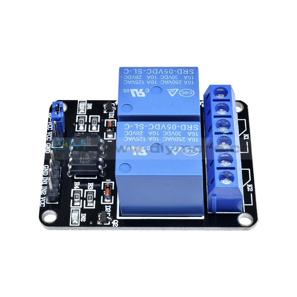
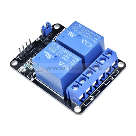 Translation missing: en.products.product.regular_price $4.99{"id":4896534233159,"title":"DC 24V 4 Channel Relay Control Switch RS485\/TTL Anti-reverse Connection Module","handle":"dc-24v-4-channel-relay-control-switch-rs485-ttl-anti-reverse-connection-module","description":"\u003cdiv data-mce-fragment=\"1\"\u003e\u003cspan lang=\"en\" data-mce-fragment=\"1\"\u003e\u003cstrong data-mce-fragment=\"1\"\u003eOverview:\u003c\/strong\u003e\u003c\/span\u003e\u003c\/div\u003e\n\u003cdiv data-mce-fragment=\"1\"\u003e\n\u003cul\u003e\n\u003cli\u003e\u003cspan lang=\"en\" data-mce-fragment=\"1\"\u003eElsay four-way Modbus relay module is equipped with mature and stable 8-bit MCU and RS485 level communication chip. Using standard MODBUS RTU format RS485 communication protocol, it can realize 4 input signal detection and 4 relay output, which can be used for digital detection or power control occasions.\u003c\/span\u003e\u003c\/li\u003e\n\u003c\/ul\u003e\n\u003cspan lang=\"en\" data-mce-fragment=\"1\"\u003e\u003cspan lang=\"en\" data-mce-fragment=\"1\"\u003e\u003cstrong data-mce-fragment=\"1\"\u003eFeatures:\u003c\/strong\u003e\u003cbr data-mce-fragment=\"1\"\u003e\u003c\/span\u003e\u003c\/span\u003e\n\u003cul\u003e\n\u003cli\u003e\u003cspan lang=\"en\" data-mce-fragment=\"1\"\u003eOnboard mature and stable 8bit MCU and MAX485 level conversion chip;\u003c\/span\u003e\u003c\/li\u003e\n\u003cli\u003e\u003cspan lang=\"en\" data-mce-fragment=\"1\"\u003eCommunication protocol: support standard Modbus RTU protocol;\u003c\/span\u003e\u003c\/li\u003e\n\u003cli\u003e\u003cspan lang=\"en\" data-mce-fragment=\"1\"\u003eCommunication interface: support RS485\/TTL UART interface;\u003c\/span\u003e\u003c\/li\u003e\n\u003cli\u003e\u003cspan lang=\"en\" data-mce-fragment=\"1\"\u003eCommunication baud rate: 4800\/9600\/19200, the default is 9600bps, and it supports power-off save;\u003c\/span\u003e\u003c\/li\u003e\n\u003cli\u003e\u003cspan lang=\"en\" data-mce-fragment=\"1\"\u003eOptocoupler input signal range: DC3.3-30V (this input cannot be used for relay control);\u003c\/span\u003e\u003c\/li\u003e\n\u003cli\u003e\u003cspan lang=\"en\" data-mce-fragment=\"1\"\u003eOutput signal: relay switch signal, support manual, flash off, flash off mode, flash off\/flash off delay base is 0.1S, the maximum flash off\/flash off time can be set to 0xFFFF*0.1S=6553.5S;\u003c\/span\u003e\u003c\/li\u003e\n\u003cli\u003e\u003cspan lang=\"en\" data-mce-fragment=\"1\"\u003eDevice address: range 1-255, default 255, support power-off save;\u003c\/span\u003e\u003c\/li\u003e\n\u003cli\u003e\u003cspan lang=\"en\" data-mce-fragment=\"1\"\u003eThe baud rate, input signal, relay status, and device address can be read using software\/commands;\u003c\/span\u003e\u003c\/li\u003e\n\u003cli\u003e\u003cspan lang=\"en\" data-mce-fragment=\"1\"\u003eThere are 4 5V, 10A\/250V AC 10A\/30V DC relays on board, which can be activated continuously for 100,000 times, with diode effusion protection, and short response time;\u003c\/span\u003e\u003c\/li\u003e\n\u003cli\u003e\u003cspan lang=\"en\" data-mce-fragment=\"1\"\u003eOn-board relay switch indicator;\u003c\/span\u003e\u003c\/li\u003e\n\u003cli\u003e\u003cspan lang=\"en\" data-mce-fragment=\"1\"\u003ePower supply voltage: DC7-24V, support DC socket\/5.08mm terminal power supply, with input anti-reverse protection;\u003c\/span\u003e\u003c\/li\u003e\n\u003c\/ul\u003e\n\u003c\/div\u003e\n\u003cdiv data-mce-fragment=\"1\"\u003e\u003cspan data-mce-fragment=\"1\"\u003e\u003cstrong data-mce-fragment=\"1\"\u003e\u003cspan lang=\"en\" data-mce-fragment=\"1\"\u003e\u003cspan title=\"\" data-mce-fragment=\"1\"\u003eHardware introduction and description\u003c\/span\u003e\u003c\/span\u003e\u003c\/strong\u003e\u003c\/span\u003e\u003c\/div\u003e\n\u003cdiv data-mce-fragment=\"1\"\u003e\u003cspan lang=\"en\" data-mce-fragment=\"1\"\u003e\u003cspan title=\"\" data-mce-fragment=\"1\"\u003eBoard size\u003c\/span\u003e\u003c\/span\u003e\u003c\/div\u003e\n\u003cdiv data-mce-fragment=\"1\"\u003e\u003cspan lang=\"en\" data-mce-fragment=\"1\"\u003e\u003cspan title=\"\" data-mce-fragment=\"1\"\u003e\u003cimg src=\"https:\/\/pg-cdn-a2.datacaciques.com\/00\/NDAy\/20\/10\/27\/759miw180130a6g1\/f50580d1c231c450.jpg\" data-mce-fragment=\"1\" data-mce-src=\"https:\/\/pg-cdn-a2.datacaciques.com\/00\/NDAy\/20\/10\/27\/759miw180130a6g1\/f50580d1c231c450.jpg\"\u003e\u003c\/span\u003e\u003c\/span\u003e\u003c\/div\u003e\n\u003cdiv data-mce-fragment=\"1\"\u003e\u003cspan lang=\"en\" data-mce-fragment=\"1\"\u003e\u003cspan title=\"\" data-mce-fragment=\"1\"\u003eInterface introduction\u003c\/span\u003e\u003c\/span\u003e\u003c\/div\u003e\n\u003cdiv data-mce-fragment=\"1\"\u003e\u003cspan lang=\"en\" data-mce-fragment=\"1\"\u003e\u003cspan title=\"\" data-mce-fragment=\"1\"\u003e\u003cimg src=\"https:\/\/pg-cdn-a2.datacaciques.com\/00\/NDAy\/20\/10\/27\/759miw180130a6g1\/4bc7a5d2ad0c45a2.jpg\" data-mce-fragment=\"1\" data-mce-src=\"https:\/\/pg-cdn-a2.datacaciques.com\/00\/NDAy\/20\/10\/27\/759miw180130a6g1\/4bc7a5d2ad0c45a2.jpg\"\u003e\u003c\/span\u003e\u003c\/span\u003e\u003c\/div\u003e\n\u003cdiv data-mce-fragment=\"1\"\u003e\n\u003cul\u003e\n\u003cli\u003e\u003cspan lang=\"en\" data-mce-fragment=\"1\"\u003e\u003cspan title=\"\" data-mce-fragment=\"1\"\u003eDC-005 socket: DC7-24V power input socket;\u003c\/span\u003e\u003c\/span\u003e\u003c\/li\u003e\n\u003cli\u003e\u003cspan lang=\"en\" data-mce-fragment=\"1\"\u003e\u003cspan title=\"\" data-mce-fragment=\"1\"\u003eVCC, GND: DC7-24V 5.08mm power input terminal;\u003c\/span\u003e\u003c\/span\u003e\u003c\/li\u003e\n\u003cli\u003e\u003cspan lang=\"en\" data-mce-fragment=\"1\"\u003e\u003cspan title=\"\" data-mce-fragment=\"1\"\u003eDC3.3-30V optocoupler signal input:\u003c\/span\u003e\u003c\/span\u003e\u003c\/li\u003e\n\u003cli\u003e\u003cspan lang=\"en\" data-mce-fragment=\"1\"\u003e\u003cspan title=\"\" data-mce-fragment=\"1\"\u003eIN1: Channel 1 positive\u003c\/span\u003e\u003c\/span\u003e\u003c\/li\u003e\n\u003cli\u003e\u003cspan lang=\"en\" data-mce-fragment=\"1\"\u003e\u003cspan title=\"\" data-mce-fragment=\"1\"\u003eIN2: Channel 2 positive\u003c\/span\u003e\u003c\/span\u003e\u003c\/li\u003e\n\u003cli\u003e\u003cspan lang=\"en\" data-mce-fragment=\"1\"\u003e\u003cspan title=\"\" data-mce-fragment=\"1\"\u003eIN3: Channel 3 positive\u003c\/span\u003e\u003c\/span\u003e\u003c\/li\u003e\n\u003cli\u003e\u003cspan lang=\"en\" data-mce-fragment=\"1\"\u003e\u003cspan title=\"\" data-mce-fragment=\"1\"\u003eIN4: Channel 4 positive\u003c\/span\u003e\u003c\/span\u003e\u003c\/li\u003e\n\u003cli\u003e\u003cspan lang=\"en\" data-mce-fragment=\"1\"\u003e\u003cspan title=\"\" data-mce-fragment=\"1\"\u003eGND_IN: Common terminal negative\u003c\/span\u003e\u003c\/span\u003e\u003c\/li\u003e\n\u003cli\u003e\u003cspan lang=\"en\" data-mce-fragment=\"1\"\u003e\u003cspan title=\"\" data-mce-fragment=\"1\"\u003eA+, B-: RS485 communication interface, A+, B- are respectively connected to A+, B- of the external control terminal;\u003c\/span\u003e\u003c\/span\u003e\u003c\/li\u003e\n\u003c\/ul\u003e\n\u003cspan lang=\"en\" data-mce-fragment=\"1\"\u003e\u003cspan lang=\"en\" data-mce-fragment=\"1\"\u003e\u003cspan title=\"\" data-mce-fragment=\"1\"\u003e\u003cstrong\u003eRelay switch signal output:\u003c\/strong\u003e\u003cbr data-mce-fragment=\"1\"\u003e\u003c\/span\u003e\u003c\/span\u003e\u003c\/span\u003e\n\u003cul\u003e\n\u003cli\u003e\u003cspan lang=\"en\" data-mce-fragment=\"1\"\u003e\u003cspan title=\"\" data-mce-fragment=\"1\"\u003eNC: Normally closed terminal, the relay is short-connected with COM before it is closed, and it is suspended after it is closed;\u003c\/span\u003e\u003c\/span\u003e\u003c\/li\u003e\n\u003cli\u003e\u003cspan lang=\"en\" data-mce-fragment=\"1\"\u003e\u003cspan title=\"\" data-mce-fragment=\"1\"\u003eCOM: public end;\u003c\/span\u003e\u003c\/span\u003e\u003c\/li\u003e\n\u003cli\u003e\u003cspan lang=\"en\" data-mce-fragment=\"1\"\u003e\u003cspan title=\"\" data-mce-fragment=\"1\"\u003eNO: Normally open end, the relay is suspended before closing, and shorted to COM after closing.\u003c\/span\u003e\u003c\/span\u003e\u003c\/li\u003e\n\u003cli\u003e\u003cspan lang=\"en\" data-mce-fragment=\"1\"\u003e\u003cspan title=\"\" data-mce-fragment=\"1\"\u003e6, GND, RXD, TXD: TTL level UART communication interface, GND, RXD, TXD are respectively connected to GND, TXD, RXD of the external control terminal;\u003c\/span\u003e\u003c\/span\u003e\u003c\/li\u003e\n\u003c\/ul\u003e\n\u003c\/div\u003e\n\u003cdiv data-mce-fragment=\"1\"\u003e\n\u003cspan lang=\"en\" data-mce-fragment=\"1\"\u003e\u003cspan lang=\"en\" data-mce-fragment=\"1\"\u003e\u003cspan title=\"\" data-mce-fragment=\"1\"\u003e\u003cstrong data-mce-fragment=\"1\"\u003eProduct Parameters:\u003c\/strong\u003e\u003cbr data-mce-fragment=\"1\"\u003e\u003c\/span\u003e\u003c\/span\u003e\u003c\/span\u003e\n\u003cul\u003e\n\u003cli\u003e\u003cspan lang=\"en\" data-mce-fragment=\"1\"\u003e\u003cspan title=\"\" data-mce-fragment=\"1\"\u003eItem name: 4CH Modbus Relay Module \u003c\/span\u003e\u003c\/span\u003e\u003c\/li\u003e\n\u003cli\u003e\u003cspan lang=\"en\" data-mce-fragment=\"1\"\u003e\u003cspan title=\"\" data-mce-fragment=\"1\"\u003eWork voltage:DC 7V~24V\u003c\/span\u003e\u003c\/span\u003e\u003c\/li\u003e\n\u003cli\u003e\u003cspan lang=\"en\" data-mce-fragment=\"1\"\u003e\u003cspan title=\"\" data-mce-fragment=\"1\"\u003eBaud rate:4800\/9600\/19600bps(default 9600bps)\u003c\/span\u003e\u003c\/span\u003e\u003c\/li\u003e\n\u003cli\u003e\u003cspan lang=\"en\" data-mce-fragment=\"1\"\u003e\u003cspan title=\"\" data-mce-fragment=\"1\"\u003eOptocoupler input signal:DC 3.3V~30V\u003c\/span\u003e\u003c\/span\u003e\u003c\/li\u003e\n\u003cli\u003e\u003cspan lang=\"en\" data-mce-fragment=\"1\"\u003e\u003cspan title=\"\" data-mce-fragment=\"1\"\u003eSet address:1~255\u003c\/span\u003e\u003c\/span\u003e\u003c\/li\u003e\n\u003cli\u003e\u003cspan lang=\"en\" data-mce-fragment=\"1\"\u003e\u003cspan title=\"\" data-mce-fragment=\"1\"\u003eRelay contorl mode: ON\/OFF,Delay_ON,Delay_OFF mode\u003c\/span\u003e\u003c\/span\u003e\u003c\/li\u003e\n\u003cli\u003e\u003cspan lang=\"en\" data-mce-fragment=\"1\"\u003e\u003cspan title=\"\" data-mce-fragment=\"1\"\u003eDelay time: 0~6553.5s \u003c\/span\u003e\u003c\/span\u003e\u003c\/li\u003e\n\u003cli\u003e\u003cspan lang=\"en\" data-mce-fragment=\"1\"\u003e\u003cspan title=\"\" data-mce-fragment=\"1\"\u003eLoad: AC 250V 10A or DC 28V 10A\u003c\/span\u003e\u003c\/span\u003e\u003c\/li\u003e\n\u003cli\u003e\u003cspan lang=\"en\" data-mce-fragment=\"1\"\u003e\u003cspan title=\"\" data-mce-fragment=\"1\"\u003eProtocol:Modbus RTU\u003c\/span\u003e\u003c\/span\u003e\u003c\/li\u003e\n\u003cli\u003e\u003cspan lang=\"en\" data-mce-fragment=\"1\"\u003e\u003cspan title=\"\" data-mce-fragment=\"1\"\u003eInterface:RS485\/TTL UART\u003c\/span\u003e\u003c\/span\u003e\u003c\/li\u003e\n\u003cli\u003e\u003cspan lang=\"en\" data-mce-fragment=\"1\"\u003e\u003cspan title=\"\" data-mce-fragment=\"1\"\u003eControl channel: 4channel\u003c\/span\u003e\u003c\/span\u003e\u003c\/li\u003e\n\u003cli\u003e\u003cspan lang=\"en\" data-mce-fragment=\"1\"\u003e\u003cspan title=\"\" data-mce-fragment=\"1\"\u003eOperating Temperature:-20℃~85℃\u003c\/span\u003e\u003c\/span\u003e\u003c\/li\u003e\n\u003cli\u003e\u003cspan lang=\"en\" data-mce-fragment=\"1\"\u003e\u003cspan title=\"\" data-mce-fragment=\"1\"\u003eOperating Humidity:5%~95%RH\u003c\/span\u003e\u003c\/span\u003e\u003c\/li\u003e\n\u003cli\u003e\u003cspan lang=\"en\" data-mce-fragment=\"1\"\u003e\u003cspan title=\"\" data-mce-fragment=\"1\"\u003eModule Size:93*90*20mm\u003c\/span\u003e\u003c\/span\u003e\u003c\/li\u003e\n\u003c\/ul\u003e\n\u003cspan lang=\"en\" data-mce-fragment=\"1\"\u003e\u003cspan lang=\"en\" data-mce-fragment=\"1\"\u003e\u003cspan title=\"\" data-mce-fragment=\"1\"\u003e\u003cimg src=\"https:\/\/pg-cdn-a2.datacaciques.com\/00\/NDAy\/20\/10\/27\/759miw180130a6g1\/5a40dd1349231871.jpg\" data-mce-fragment=\"1\" data-mce-src=\"https:\/\/pg-cdn-a2.datacaciques.com\/00\/NDAy\/20\/10\/27\/759miw180130a6g1\/5a40dd1349231871.jpg\"\u003e\u003cbr data-mce-fragment=\"1\"\u003e\u003cstrong data-mce-fragment=\"1\"\u003eModbus RTU Command:\u003c\/strong\u003e\u003cbr data-mce-fragment=\"1\"\u003e\u003c\/span\u003e\u003c\/span\u003e\u003c\/span\u003e\n\u003cul\u003e\n\u003cli\u003e\u003cspan lang=\"en\" data-mce-fragment=\"1\"\u003e\u003cspan title=\"\" data-mce-fragment=\"1\"\u003eSuppose the device address is 0xFF so return 00 10 00 00 00 01 02 00 FF EB 80 and the 9th btye is device address.\u003c\/span\u003e\u003c\/span\u003e\u003c\/li\u003e\n\u003cli\u003e\u003cspan lang=\"en\" data-mce-fragment=\"1\"\u003e\u003cspan title=\"\" data-mce-fragment=\"1\"\u003eTurn ON CH_1 Relay(Normal Mode):\u003c\/span\u003e\u003c\/span\u003e\u003c\/li\u003e\n\u003cli\u003e\u003cspan lang=\"en\" data-mce-fragment=\"1\"\u003e\u003cspan title=\"\" data-mce-fragment=\"1\"\u003e Send: FF 05 00 00 FF 00 99 E4\u003c\/span\u003e\u003c\/span\u003e\u003c\/li\u003e\n\u003cli\u003e\u003cspan lang=\"en\" data-mce-fragment=\"1\"\u003e\u003cspan title=\"\" data-mce-fragment=\"1\"\u003e Return: FF 05 00 00 FF 00 99 E4\u003c\/span\u003e\u003c\/span\u003e\u003c\/li\u003e\n\u003cli\u003e\u003cspan lang=\"en\" data-mce-fragment=\"1\"\u003e\u003cspan title=\"\" data-mce-fragment=\"1\"\u003e Note_1:The 3rd and 4th byte are relay addresses.So it can be 0x0000,0x0001,0x0002,0x0003.\u003c\/span\u003e\u003c\/span\u003e\u003c\/li\u003e\n\u003cli\u003e\u003cspan lang=\"en\" data-mce-fragment=\"1\"\u003e\u003cspan title=\"\" data-mce-fragment=\"1\"\u003e Note_2:The 5th and 6th byte are relay data.0xFF00 means turn ON relay and 0x0000 means turn OFF relay.\u003c\/span\u003e\u003c\/span\u003e\u003c\/li\u003e\n\u003cli\u003e\u003cspan lang=\"en\" data-mce-fragment=\"1\"\u003e\u003cspan title=\"\" data-mce-fragment=\"1\"\u003eTurn OFF CH_1 Relay(Normal Mode):\u003c\/span\u003e\u003c\/span\u003e\u003c\/li\u003e\n\u003cli\u003e\u003cspan lang=\"en\" data-mce-fragment=\"1\"\u003e\u003cspan title=\"\" data-mce-fragment=\"1\"\u003e Send: FF 05 00 00 00 00 D8 14\u003c\/span\u003e\u003c\/span\u003e\u003c\/li\u003e\n\u003cli\u003e\u003cspan lang=\"en\" data-mce-fragment=\"1\"\u003e\u003cspan title=\"\" data-mce-fragment=\"1\"\u003e Return: FF 05 00 00 00 00 D8 14\u003c\/span\u003e\u003c\/span\u003e\u003c\/li\u003e\n\u003cli\u003e\u003cspan lang=\"en\" data-mce-fragment=\"1\"\u003e\u003cspan title=\"\" data-mce-fragment=\"1\"\u003eTurn ON CH_2 Relay(Normal Mode):\u003c\/span\u003e\u003c\/span\u003e\u003c\/li\u003e\n\u003cli\u003e\u003cspan lang=\"en\" data-mce-fragment=\"1\"\u003e\u003cspan title=\"\" data-mce-fragment=\"1\"\u003e Send: FF 05 00 01 FF 00 C8 24\u003c\/span\u003e\u003c\/span\u003e\u003c\/li\u003e\n\u003cli\u003e\u003cspan lang=\"en\" data-mce-fragment=\"1\"\u003e\u003cspan title=\"\" data-mce-fragment=\"1\"\u003e Return: FF 05 00 01 FF 00 C8 24\u003c\/span\u003e\u003c\/span\u003e\u003c\/li\u003e\n\u003cli\u003e\u003cspan lang=\"en\" data-mce-fragment=\"1\"\u003e\u003cspan title=\"\" data-mce-fragment=\"1\"\u003eTurn OFF CH_2 Relay(Normal Mode):\u003c\/span\u003e\u003c\/span\u003e\u003c\/li\u003e\n\u003cli\u003e\u003cspan lang=\"en\" data-mce-fragment=\"1\"\u003e\u003cspan title=\"\" data-mce-fragment=\"1\"\u003e Send: FF 05 00 01 00 00 89 D4\u003c\/span\u003e\u003c\/span\u003e\u003c\/li\u003e\n\u003cli\u003e\u003cspan lang=\"en\" data-mce-fragment=\"1\"\u003e\u003cspan title=\"\" data-mce-fragment=\"1\"\u003e Return: FF 05 00 01 00 00 89 D4\u003c\/span\u003e\u003c\/span\u003e\u003c\/li\u003e\n\u003cli\u003e\u003cspan lang=\"en\" data-mce-fragment=\"1\"\u003e\u003cspan title=\"\" data-mce-fragment=\"1\"\u003eTurn ON All relays:\u003c\/span\u003e\u003c\/span\u003e\u003c\/li\u003e\n\u003cli\u003e\u003cspan lang=\"en\" data-mce-fragment=\"1\"\u003e\u003cspan title=\"\" data-mce-fragment=\"1\"\u003e Send: FF 0F 00 00 00 08 01 FF 30 1D\u003c\/span\u003e\u003c\/span\u003e\u003c\/li\u003e\n\u003cli\u003e\u003cspan lang=\"en\" data-mce-fragment=\"1\"\u003e\u003cspan title=\"\" data-mce-fragment=\"1\"\u003e Return: FF 0F 00 00 00 08 41 D3\u003c\/span\u003e\u003c\/span\u003e\u003c\/li\u003e\n\u003cli\u003e\u003cspan lang=\"en\" data-mce-fragment=\"1\"\u003e\u003cspan title=\"\" data-mce-fragment=\"1\"\u003eTurn OFF All relays:\u003c\/span\u003e\u003c\/span\u003e\u003c\/li\u003e\n\u003cli\u003e\u003cspan lang=\"en\" data-mce-fragment=\"1\"\u003e\u003cspan title=\"\" data-mce-fragment=\"1\"\u003e Send: FF 0F 00 00 00 08 01 00 70 5D\u003c\/span\u003e\u003c\/span\u003e\u003c\/li\u003e\n\u003cli\u003e\u003cspan lang=\"en\" data-mce-fragment=\"1\"\u003e\u003cspan title=\"\" data-mce-fragment=\"1\"\u003e Return: FF 0F 00 00 00 08 41 D3\u003c\/span\u003e\u003c\/span\u003e\u003c\/li\u003e\n\u003cli\u003e\u003cspan lang=\"en\" data-mce-fragment=\"1\"\u003e\u003cspan title=\"\" data-mce-fragment=\"1\"\u003eSet device address to 0x01:\u003c\/span\u003e\u003c\/span\u003e\u003c\/li\u003e\n\u003cli\u003e\u003cspan lang=\"en\" data-mce-fragment=\"1\"\u003e\u003cspan title=\"\" data-mce-fragment=\"1\"\u003e Send: 00 10 00 00 00 01 02 00 01 6A 00\u003c\/span\u003e\u003c\/span\u003e\u003c\/li\u003e\n\u003cli\u003e\u003cspan lang=\"en\" data-mce-fragment=\"1\"\u003e\u003cspan title=\"\" data-mce-fragment=\"1\"\u003e Return: 00 10 00 00 00 01 02 00 01 6A 00\u003c\/span\u003e\u003c\/span\u003e\u003c\/li\u003e\n\u003cli\u003e\u003cspan lang=\"en\" data-mce-fragment=\"1\"\u003e\u003cspan title=\"\" data-mce-fragment=\"1\"\u003e Note: The 9th btye is device address.\u003c\/span\u003e\u003c\/span\u003e\u003c\/li\u003e\n\u003cli\u003e\u003cspan lang=\"en\" data-mce-fragment=\"1\"\u003e\u003cspan title=\"\" data-mce-fragment=\"1\"\u003eSet device address to 0xFF:\u003c\/span\u003e\u003c\/span\u003e\u003c\/li\u003e\n\u003cli\u003e\u003cspan lang=\"en\" data-mce-fragment=\"1\"\u003e\u003cspan title=\"\" data-mce-fragment=\"1\"\u003e Send: 00 10 00 00 00 01 02 00 FF EB 80\u003c\/span\u003e\u003c\/span\u003e\u003c\/li\u003e\n\u003cli\u003e\u003cspan lang=\"en\" data-mce-fragment=\"1\"\u003e\u003cspan title=\"\" data-mce-fragment=\"1\"\u003e Return: 00 10 00 00 00 01 02 00 FF EB 80\u003c\/span\u003e\u003c\/span\u003e\u003c\/li\u003e\n\u003cli\u003e\u003cspan lang=\"en\" data-mce-fragment=\"1\"\u003e\u003cspan title=\"\" data-mce-fragment=\"1\"\u003eRead device address:\u003c\/span\u003e\u003c\/span\u003e\u003c\/li\u003e\n\u003cli\u003e\u003cspan lang=\"en\" data-mce-fragment=\"1\"\u003e\u003cspan title=\"\" data-mce-fragment=\"1\"\u003e Send: 00 03 00 00 00 01 85 DB\u003c\/span\u003e\u003c\/span\u003e\u003c\/li\u003e\n\u003cli\u003e\u003cspan lang=\"en\" data-mce-fragment=\"1\"\u003e\u003cspan title=\"\" data-mce-fragment=\"1\"\u003e Return: 00 03 02 00 FF C5 C4\u003c\/span\u003e\u003c\/span\u003e\u003c\/li\u003e\n\u003cli\u003e\u003cspan lang=\"en\" data-mce-fragment=\"1\"\u003e\u003cspan title=\"\" data-mce-fragment=\"1\"\u003e Note: The 5th btye is device address.\u003c\/span\u003e\u003c\/span\u003e\u003c\/li\u003e\n\u003cli\u003e\u003cspan lang=\"en\" data-mce-fragment=\"1\"\u003e\u003cspan title=\"\" data-mce-fragment=\"1\"\u003eRead relay status:\u003c\/span\u003e\u003c\/span\u003e\u003c\/li\u003e\n\u003cli\u003e\u003cspan lang=\"en\" data-mce-fragment=\"1\"\u003e\u003cspan title=\"\" data-mce-fragment=\"1\"\u003e Send: FF 01 00 00 00 08 28 12\u003c\/span\u003e\u003c\/span\u003e\u003c\/li\u003e\n\u003cli\u003e\u003cspan lang=\"en\" data-mce-fragment=\"1\"\u003e\u003cspan title=\"\" data-mce-fragment=\"1\"\u003e Return: FF 01 01 01 A1 A0\u003c\/span\u003e\u003c\/span\u003e\u003c\/li\u003e\n\u003cli\u003e\u003cspan lang=\"en\" data-mce-fragment=\"1\"\u003e\u003cspan title=\"\" data-mce-fragment=\"1\"\u003e Note:The 4th means which one relay.0 means OFF and 1 means ON.\u003c\/span\u003e\u003c\/span\u003e\u003c\/li\u003e\n\u003cli\u003e\u003cspan lang=\"en\" data-mce-fragment=\"1\"\u003e\u003cspan title=\"\" data-mce-fragment=\"1\"\u003eRead optocoupler input staturs:\u003c\/span\u003e\u003c\/span\u003e\u003c\/li\u003e\n\u003cli\u003e\u003cspan lang=\"en\" data-mce-fragment=\"1\"\u003e\u003cspan title=\"\" data-mce-fragment=\"1\"\u003e Send: FF 02 00 00 00 08 6C 12\u003c\/span\u003e\u003c\/span\u003e\u003c\/li\u003e\n\u003cli\u003e\u003cspan lang=\"en\" data-mce-fragment=\"1\"\u003e\u003cspan title=\"\" data-mce-fragment=\"1\"\u003e Return: FF 02 01 01 51 A0\u003c\/span\u003e\u003c\/span\u003e\u003c\/li\u003e\n\u003cli\u003e\u003cspan lang=\"en\" data-mce-fragment=\"1\"\u003e\u003cspan title=\"\" data-mce-fragment=\"1\"\u003e Note:The 4th means which one input.0 means low level signal input and 1 means high level signal input.\u003c\/span\u003e\u003c\/span\u003e\u003c\/li\u003e\n\u003cli\u003e\u003cspan lang=\"en\" data-mce-fragment=\"1\"\u003e\u003cspan title=\"\" data-mce-fragment=\"1\"\u003eSet baud rate 4800bps:\u003c\/span\u003e\u003c\/span\u003e\u003c\/li\u003e\n\u003cli\u003e\u003cspan lang=\"en\" data-mce-fragment=\"1\"\u003e\u003cspan title=\"\" data-mce-fragment=\"1\"\u003e Send: FF 10 03 E9 00 01 02 00 02 4A 0C\u003c\/span\u003e\u003c\/span\u003e\u003c\/li\u003e\n\u003cli\u003e\u003cspan lang=\"en\" data-mce-fragment=\"1\"\u003e\u003cspan title=\"\" data-mce-fragment=\"1\"\u003e Return: FF 10 03 E9 00 01 C5 A7\u003c\/span\u003e\u003c\/span\u003e\u003c\/li\u003e\n\u003cli\u003e\u003cspan lang=\"en\" data-mce-fragment=\"1\"\u003e\u003cspan title=\"\" data-mce-fragment=\"1\"\u003e Note:The 9th btye is baud rate value.0x02 is 4800bps.0x03 is 9600bps.0x04 is 19200bps.\u003c\/span\u003e\u003c\/span\u003e\u003c\/li\u003e\n\u003cli\u003e\u003cspan lang=\"en\" data-mce-fragment=\"1\"\u003e\u003cspan title=\"\" data-mce-fragment=\"1\"\u003eSet baud rate 9600bps:\u003c\/span\u003e\u003c\/span\u003e\u003c\/li\u003e\n\u003cli\u003e\u003cspan lang=\"en\" data-mce-fragment=\"1\"\u003e\u003cspan title=\"\" data-mce-fragment=\"1\"\u003e Send: FF 10 03 E9 00 01 02 00 03 8B CC\u003c\/span\u003e\u003c\/span\u003e\u003c\/li\u003e\n\u003cli\u003e\u003cspan lang=\"en\" data-mce-fragment=\"1\"\u003e\u003cspan title=\"\" data-mce-fragment=\"1\"\u003e Return: FF 10 03 E9 00 01 C5 A7\u003c\/span\u003e\u003c\/span\u003e\u003c\/li\u003e\n\u003cli\u003e\u003cspan lang=\"en\" data-mce-fragment=\"1\"\u003e\u003cspan title=\"\" data-mce-fragment=\"1\"\u003eSet baud rate 19200bps:\u003c\/span\u003e\u003c\/span\u003e\u003c\/li\u003e\n\u003cli\u003e\u003cspan lang=\"en\" data-mce-fragment=\"1\"\u003e\u003cspan title=\"\" data-mce-fragment=\"1\"\u003e Send: FF 10 03 E9 00 01 02 00 04 CA 0E\u003c\/span\u003e\u003c\/span\u003e\u003c\/li\u003e\n\u003cli\u003e\u003cspan lang=\"en\" data-mce-fragment=\"1\"\u003e\u003cspan title=\"\" data-mce-fragment=\"1\"\u003e Return: FF 10 03 E9 00 01 C5 A7\u003c\/span\u003e\u003c\/span\u003e\u003c\/li\u003e\n\u003cli\u003e\u003cspan lang=\"en\" data-mce-fragment=\"1\"\u003e\u003cspan title=\"\" data-mce-fragment=\"1\"\u003eTurn ON CH_1 Relay(2S Flashing Mode):\u003c\/span\u003e\u003c\/span\u003e\u003c\/li\u003e\n\u003cli\u003e\u003cspan lang=\"en\" data-mce-fragment=\"1\"\u003e\u003cspan title=\"\" data-mce-fragment=\"1\"\u003e Send: FF 10 00 03 00 02 04 00 04 00 14 C5 9F\u003c\/span\u003e\u003c\/span\u003e\u003c\/li\u003e\n\u003cli\u003e\u003cspan lang=\"en\" data-mce-fragment=\"1\"\u003e\u003cspan title=\"\" data-mce-fragment=\"1\"\u003e Return: FF 10 00 03 00 02 A4 16\u003c\/span\u003e\u003c\/span\u003e\u003c\/li\u003e\n\u003cli\u003e\u003cspan lang=\"en\" data-mce-fragment=\"1\"\u003e\u003cspan title=\"\" data-mce-fragment=\"1\"\u003e Note_1:The 3rd and 4th byte are relay addresses.So CH1~CH4 can be 0x0003,0x0008,0x000D,0x0012.\u003c\/span\u003e\u003c\/span\u003e\u003c\/li\u003e\n\u003cli\u003e\u003cspan lang=\"en\" data-mce-fragment=\"1\"\u003e\u003cspan title=\"\" data-mce-fragment=\"1\"\u003e Note_2:The 10th and 11th byte are delay time in second.The minimum delay time is 0.1s.Relay will OFF after delay time.So the delay time in this command is : 0x0014*0.1=2S.\u003c\/span\u003e\u003c\/span\u003e\u003c\/li\u003e\n\u003cli\u003e\u003cspan lang=\"en\" data-mce-fragment=\"1\"\u003e\u003cspan title=\"\" data-mce-fragment=\"1\"\u003eTurn OFF CH_1 Relay(3S Flashing Mode):\u003c\/span\u003e\u003c\/span\u003e\u003c\/li\u003e\n\u003cli\u003e\u003cspan lang=\"en\" data-mce-fragment=\"1\"\u003e\u003cspan title=\"\" data-mce-fragment=\"1\"\u003e Send: FF 10 00 03 00 02 04 00 02 00 1E A5 99\u003c\/span\u003e\u003c\/span\u003e\u003c\/li\u003e\n\u003cli\u003e\u003cspan lang=\"en\" data-mce-fragment=\"1\"\u003e\u003cspan title=\"\" data-mce-fragment=\"1\"\u003e Return: FF 10 00 03 00 02 A4 16\u003c\/span\u003e\u003c\/span\u003e\u003c\/li\u003e\n\u003cli\u003e\u003cspan lang=\"en\" data-mce-fragment=\"1\"\u003e\u003cspan title=\"\" data-mce-fragment=\"1\"\u003e Note:Relay will ON after delay time.So the delay time in this command is : 0x001E*0.1=3S.\u003c\/span\u003e\u003c\/span\u003e\u003c\/li\u003e\n\u003c\/ul\u003e\n\u003cspan lang=\"en\" data-mce-fragment=\"1\"\u003e\u003cspan lang=\"en\" data-mce-fragment=\"1\"\u003e\u003cspan title=\"\" data-mce-fragment=\"1\"\u003e\u003cimg src=\"https:\/\/pg-cdn-a2.datacaciques.com\/00\/NDAy\/20\/10\/27\/759miw180130a6g1\/b4e1c2017abb1ec6.jpg\" data-mce-fragment=\"1\" data-mce-src=\"https:\/\/pg-cdn-a2.datacaciques.com\/00\/NDAy\/20\/10\/27\/759miw180130a6g1\/b4e1c2017abb1ec6.jpg\"\u003e\u003cbr data-mce-fragment=\"1\"\u003e\u003cstrong data-mce-fragment=\"1\"\u003ePackage Include:\u003c\/strong\u003e\u003cbr data-mce-fragment=\"1\"\u003e\u003c\/span\u003e\u003c\/span\u003e\u003c\/span\u003e\n\u003cul\u003e\n\u003cli\u003e\u003cspan lang=\"en\" data-mce-fragment=\"1\"\u003e\u003cspan title=\"\" data-mce-fragment=\"1\"\u003e 1PC 4CH Modbus Relay Module \u003c\/span\u003e\u003c\/span\u003e\u003c\/li\u003e\n\u003c\/ul\u003e\n\u003c\/div\u003e\n\u003cdiv data-mce-fragment=\"1\"\u003e\u003cspan lang=\"en\" data-mce-fragment=\"1\"\u003e\u003cspan title=\"\" data-mce-fragment=\"1\"\u003e \u003c\/span\u003e\u003c\/span\u003e\u003c\/div\u003e","published_at":"2020-10-29T16:43:18+08:00","created_at":"2020-10-28T12:04:09+08:00","vendor":"DIYMORE","type":"","tags":[],"price":1099,"price_min":1099,"price_max":1099,"available":true,"price_varies":false,"compare_at_price":null,"compare_at_price_min":0,"compare_at_price_max":0,"compare_at_price_varies":false,"variants":[{"id":32644275765319,"title":"Default Title","option1":"Default Title","option2":null,"option3":null,"sku":"XM0006","requires_shipping":true,"taxable":false,"featured_image":null,"available":true,"name":"DC 24V 4 Channel Relay Control Switch RS485\/TTL Anti-reverse Connection Module","public_title":null,"options":["Default Title"],"price":1099,"weight":0,"compare_at_price":null,"inventory_management":"shopify","barcode":"","requires_selling_plan":false,"selling_plan_allocations":[],"quantity_rule":{"min":1,"max":null,"increment":1}}],"images":["\/\/www.diymore.cc\/cdn\/shop\/products\/3_c1c2716b-4e56-4778-96d4-eb4ff9c7620a.jpg?v=1603857853","\/\/www.diymore.cc\/cdn\/shop\/products\/5_ff208254-a902-4d04-93e4-bce5ea8eb512.jpg?v=1603857854","\/\/www.diymore.cc\/cdn\/shop\/products\/4_0b281e6a-ef90-4366-8a24-d9a167cf31ca.jpg?v=1603857854","\/\/www.diymore.cc\/cdn\/shop\/products\/1_968bb946-a0f2-4ed7-8618-2ab8b7fa26f9.jpg?v=1603857854","\/\/www.diymore.cc\/cdn\/shop\/products\/2_5f6abbf8-5697-4e69-9c60-03559cfb6029.jpg?v=1603857854"],"featured_image":"\/\/www.diymore.cc\/cdn\/shop\/products\/3_c1c2716b-4e56-4778-96d4-eb4ff9c7620a.jpg?v=1603857853","options":["Title"],"media":[{"alt":null,"id":7652174987335,"position":1,"preview_image":{"aspect_ratio":1.0,"height":1000,"width":1000,"src":"\/\/www.diymore.cc\/cdn\/shop\/products\/3_c1c2716b-4e56-4778-96d4-eb4ff9c7620a.jpg?v=1603857853"},"aspect_ratio":1.0,"height":1000,"media_type":"image","src":"\/\/www.diymore.cc\/cdn\/shop\/products\/3_c1c2716b-4e56-4778-96d4-eb4ff9c7620a.jpg?v=1603857853","width":1000},{"alt":null,"id":7652175020103,"position":2,"preview_image":{"aspect_ratio":1.0,"height":1000,"width":1000,"src":"\/\/www.diymore.cc\/cdn\/shop\/products\/5_ff208254-a902-4d04-93e4-bce5ea8eb512.jpg?v=1603857854"},"aspect_ratio":1.0,"height":1000,"media_type":"image","src":"\/\/www.diymore.cc\/cdn\/shop\/products\/5_ff208254-a902-4d04-93e4-bce5ea8eb512.jpg?v=1603857854","width":1000},{"alt":null,"id":7652175052871,"position":3,"preview_image":{"aspect_ratio":1.0,"height":1000,"width":1000,"src":"\/\/www.diymore.cc\/cdn\/shop\/products\/4_0b281e6a-ef90-4366-8a24-d9a167cf31ca.jpg?v=1603857854"},"aspect_ratio":1.0,"height":1000,"media_type":"image","src":"\/\/www.diymore.cc\/cdn\/shop\/products\/4_0b281e6a-ef90-4366-8a24-d9a167cf31ca.jpg?v=1603857854","width":1000},{"alt":null,"id":7652175085639,"position":4,"preview_image":{"aspect_ratio":1.0,"height":1000,"width":1000,"src":"\/\/www.diymore.cc\/cdn\/shop\/products\/1_968bb946-a0f2-4ed7-8618-2ab8b7fa26f9.jpg?v=1603857854"},"aspect_ratio":1.0,"height":1000,"media_type":"image","src":"\/\/www.diymore.cc\/cdn\/shop\/products\/1_968bb946-a0f2-4ed7-8618-2ab8b7fa26f9.jpg?v=1603857854","width":1000},{"alt":null,"id":7652175118407,"position":5,"preview_image":{"aspect_ratio":1.0,"height":1000,"width":1000,"src":"\/\/www.diymore.cc\/cdn\/shop\/products\/2_5f6abbf8-5697-4e69-9c60-03559cfb6029.jpg?v=1603857854"},"aspect_ratio":1.0,"height":1000,"media_type":"image","src":"\/\/www.diymore.cc\/cdn\/shop\/products\/2_5f6abbf8-5697-4e69-9c60-03559cfb6029.jpg?v=1603857854","width":1000}],"requires_selling_plan":false,"selling_plan_groups":[],"content":"\u003cdiv data-mce-fragment=\"1\"\u003e\u003cspan lang=\"en\" data-mce-fragment=\"1\"\u003e\u003cstrong data-mce-fragment=\"1\"\u003eOverview:\u003c\/strong\u003e\u003c\/span\u003e\u003c\/div\u003e\n\u003cdiv data-mce-fragment=\"1\"\u003e\n\u003cul\u003e\n\u003cli\u003e\u003cspan lang=\"en\" data-mce-fragment=\"1\"\u003eElsay four-way Modbus relay module is equipped with mature and stable 8-bit MCU and RS485 level communication chip. Using standard MODBUS RTU format RS485 communication protocol, it can realize 4 input signal detection and 4 relay output, which can be used for digital detection or power control occasions.\u003c\/span\u003e\u003c\/li\u003e\n\u003c\/ul\u003e\n\u003cspan lang=\"en\" data-mce-fragment=\"1\"\u003e\u003cspan lang=\"en\" data-mce-fragment=\"1\"\u003e\u003cstrong data-mce-fragment=\"1\"\u003eFeatures:\u003c\/strong\u003e\u003cbr data-mce-fragment=\"1\"\u003e\u003c\/span\u003e\u003c\/span\u003e\n\u003cul\u003e\n\u003cli\u003e\u003cspan lang=\"en\" data-mce-fragment=\"1\"\u003eOnboard mature and stable 8bit MCU and MAX485 level conversion chip;\u003c\/span\u003e\u003c\/li\u003e\n\u003cli\u003e\u003cspan lang=\"en\" data-mce-fragment=\"1\"\u003eCommunication protocol: support standard Modbus RTU protocol;\u003c\/span\u003e\u003c\/li\u003e\n\u003cli\u003e\u003cspan lang=\"en\" data-mce-fragment=\"1\"\u003eCommunication interface: support RS485\/TTL UART interface;\u003c\/span\u003e\u003c\/li\u003e\n\u003cli\u003e\u003cspan lang=\"en\" data-mce-fragment=\"1\"\u003eCommunication baud rate: 4800\/9600\/19200, the default is 9600bps, and it supports power-off save;\u003c\/span\u003e\u003c\/li\u003e\n\u003cli\u003e\u003cspan lang=\"en\" data-mce-fragment=\"1\"\u003eOptocoupler input signal range: DC3.3-30V (this input cannot be used for relay control);\u003c\/span\u003e\u003c\/li\u003e\n\u003cli\u003e\u003cspan lang=\"en\" data-mce-fragment=\"1\"\u003eOutput signal: relay switch signal, support manual, flash off, flash off mode, flash off\/flash off delay base is 0.1S, the maximum flash off\/flash off time can be set to 0xFFFF*0.1S=6553.5S;\u003c\/span\u003e\u003c\/li\u003e\n\u003cli\u003e\u003cspan lang=\"en\" data-mce-fragment=\"1\"\u003eDevice address: range 1-255, default 255, support power-off save;\u003c\/span\u003e\u003c\/li\u003e\n\u003cli\u003e\u003cspan lang=\"en\" data-mce-fragment=\"1\"\u003eThe baud rate, input signal, relay status, and device address can be read using software\/commands;\u003c\/span\u003e\u003c\/li\u003e\n\u003cli\u003e\u003cspan lang=\"en\" data-mce-fragment=\"1\"\u003eThere are 4 5V, 10A\/250V AC 10A\/30V DC relays on board, which can be activated continuously for 100,000 times, with diode effusion protection, and short response time;\u003c\/span\u003e\u003c\/li\u003e\n\u003cli\u003e\u003cspan lang=\"en\" data-mce-fragment=\"1\"\u003eOn-board relay switch indicator;\u003c\/span\u003e\u003c\/li\u003e\n\u003cli\u003e\u003cspan lang=\"en\" data-mce-fragment=\"1\"\u003ePower supply voltage: DC7-24V, support DC socket\/5.08mm terminal power supply, with input anti-reverse protection;\u003c\/span\u003e\u003c\/li\u003e\n\u003c\/ul\u003e\n\u003c\/div\u003e\n\u003cdiv data-mce-fragment=\"1\"\u003e\u003cspan data-mce-fragment=\"1\"\u003e\u003cstrong data-mce-fragment=\"1\"\u003e\u003cspan lang=\"en\" data-mce-fragment=\"1\"\u003e\u003cspan title=\"\" data-mce-fragment=\"1\"\u003eHardware introduction and description\u003c\/span\u003e\u003c\/span\u003e\u003c\/strong\u003e\u003c\/span\u003e\u003c\/div\u003e\n\u003cdiv data-mce-fragment=\"1\"\u003e\u003cspan lang=\"en\" data-mce-fragment=\"1\"\u003e\u003cspan title=\"\" data-mce-fragment=\"1\"\u003eBoard size\u003c\/span\u003e\u003c\/span\u003e\u003c\/div\u003e\n\u003cdiv data-mce-fragment=\"1\"\u003e\u003cspan lang=\"en\" data-mce-fragment=\"1\"\u003e\u003cspan title=\"\" data-mce-fragment=\"1\"\u003e\u003cimg src=\"https:\/\/pg-cdn-a2.datacaciques.com\/00\/NDAy\/20\/10\/27\/759miw180130a6g1\/f50580d1c231c450.jpg\" data-mce-fragment=\"1\" data-mce-src=\"https:\/\/pg-cdn-a2.datacaciques.com\/00\/NDAy\/20\/10\/27\/759miw180130a6g1\/f50580d1c231c450.jpg\"\u003e\u003c\/span\u003e\u003c\/span\u003e\u003c\/div\u003e\n\u003cdiv data-mce-fragment=\"1\"\u003e\u003cspan lang=\"en\" data-mce-fragment=\"1\"\u003e\u003cspan title=\"\" data-mce-fragment=\"1\"\u003eInterface introduction\u003c\/span\u003e\u003c\/span\u003e\u003c\/div\u003e\n\u003cdiv data-mce-fragment=\"1\"\u003e\u003cspan lang=\"en\" data-mce-fragment=\"1\"\u003e\u003cspan title=\"\" data-mce-fragment=\"1\"\u003e\u003cimg src=\"https:\/\/pg-cdn-a2.datacaciques.com\/00\/NDAy\/20\/10\/27\/759miw180130a6g1\/4bc7a5d2ad0c45a2.jpg\" data-mce-fragment=\"1\" data-mce-src=\"https:\/\/pg-cdn-a2.datacaciques.com\/00\/NDAy\/20\/10\/27\/759miw180130a6g1\/4bc7a5d2ad0c45a2.jpg\"\u003e\u003c\/span\u003e\u003c\/span\u003e\u003c\/div\u003e\n\u003cdiv data-mce-fragment=\"1\"\u003e\n\u003cul\u003e\n\u003cli\u003e\u003cspan lang=\"en\" data-mce-fragment=\"1\"\u003e\u003cspan title=\"\" data-mce-fragment=\"1\"\u003eDC-005 socket: DC7-24V power input socket;\u003c\/span\u003e\u003c\/span\u003e\u003c\/li\u003e\n\u003cli\u003e\u003cspan lang=\"en\" data-mce-fragment=\"1\"\u003e\u003cspan title=\"\" data-mce-fragment=\"1\"\u003eVCC, GND: DC7-24V 5.08mm power input terminal;\u003c\/span\u003e\u003c\/span\u003e\u003c\/li\u003e\n\u003cli\u003e\u003cspan lang=\"en\" data-mce-fragment=\"1\"\u003e\u003cspan title=\"\" data-mce-fragment=\"1\"\u003eDC3.3-30V optocoupler signal input:\u003c\/span\u003e\u003c\/span\u003e\u003c\/li\u003e\n\u003cli\u003e\u003cspan lang=\"en\" data-mce-fragment=\"1\"\u003e\u003cspan title=\"\" data-mce-fragment=\"1\"\u003eIN1: Channel 1 positive\u003c\/span\u003e\u003c\/span\u003e\u003c\/li\u003e\n\u003cli\u003e\u003cspan lang=\"en\" data-mce-fragment=\"1\"\u003e\u003cspan title=\"\" data-mce-fragment=\"1\"\u003eIN2: Channel 2 positive\u003c\/span\u003e\u003c\/span\u003e\u003c\/li\u003e\n\u003cli\u003e\u003cspan lang=\"en\" data-mce-fragment=\"1\"\u003e\u003cspan title=\"\" data-mce-fragment=\"1\"\u003eIN3: Channel 3 positive\u003c\/span\u003e\u003c\/span\u003e\u003c\/li\u003e\n\u003cli\u003e\u003cspan lang=\"en\" data-mce-fragment=\"1\"\u003e\u003cspan title=\"\" data-mce-fragment=\"1\"\u003eIN4: Channel 4 positive\u003c\/span\u003e\u003c\/span\u003e\u003c\/li\u003e\n\u003cli\u003e\u003cspan lang=\"en\" data-mce-fragment=\"1\"\u003e\u003cspan title=\"\" data-mce-fragment=\"1\"\u003eGND_IN: Common terminal negative\u003c\/span\u003e\u003c\/span\u003e\u003c\/li\u003e\n\u003cli\u003e\u003cspan lang=\"en\" data-mce-fragment=\"1\"\u003e\u003cspan title=\"\" data-mce-fragment=\"1\"\u003eA+, B-: RS485 communication interface, A+, B- are respectively connected to A+, B- of the external control terminal;\u003c\/span\u003e\u003c\/span\u003e\u003c\/li\u003e\n\u003c\/ul\u003e\n\u003cspan lang=\"en\" data-mce-fragment=\"1\"\u003e\u003cspan lang=\"en\" data-mce-fragment=\"1\"\u003e\u003cspan title=\"\" data-mce-fragment=\"1\"\u003e\u003cstrong\u003eRelay switch signal output:\u003c\/strong\u003e\u003cbr data-mce-fragment=\"1\"\u003e\u003c\/span\u003e\u003c\/span\u003e\u003c\/span\u003e\n\u003cul\u003e\n\u003cli\u003e\u003cspan lang=\"en\" data-mce-fragment=\"1\"\u003e\u003cspan title=\"\" data-mce-fragment=\"1\"\u003eNC: Normally closed terminal, the relay is short-connected with COM before it is closed, and it is suspended after it is closed;\u003c\/span\u003e\u003c\/span\u003e\u003c\/li\u003e\n\u003cli\u003e\u003cspan lang=\"en\" data-mce-fragment=\"1\"\u003e\u003cspan title=\"\" data-mce-fragment=\"1\"\u003eCOM: public end;\u003c\/span\u003e\u003c\/span\u003e\u003c\/li\u003e\n\u003cli\u003e\u003cspan lang=\"en\" data-mce-fragment=\"1\"\u003e\u003cspan title=\"\" data-mce-fragment=\"1\"\u003eNO: Normally open end, the relay is suspended before closing, and shorted to COM after closing.\u003c\/span\u003e\u003c\/span\u003e\u003c\/li\u003e\n\u003cli\u003e\u003cspan lang=\"en\" data-mce-fragment=\"1\"\u003e\u003cspan title=\"\" data-mce-fragment=\"1\"\u003e6, GND, RXD, TXD: TTL level UART communication interface, GND, RXD, TXD are respectively connected to GND, TXD, RXD of the external control terminal;\u003c\/span\u003e\u003c\/span\u003e\u003c\/li\u003e\n\u003c\/ul\u003e\n\u003c\/div\u003e\n\u003cdiv data-mce-fragment=\"1\"\u003e\n\u003cspan lang=\"en\" data-mce-fragment=\"1\"\u003e\u003cspan lang=\"en\" data-mce-fragment=\"1\"\u003e\u003cspan title=\"\" data-mce-fragment=\"1\"\u003e\u003cstrong data-mce-fragment=\"1\"\u003eProduct Parameters:\u003c\/strong\u003e\u003cbr data-mce-fragment=\"1\"\u003e\u003c\/span\u003e\u003c\/span\u003e\u003c\/span\u003e\n\u003cul\u003e\n\u003cli\u003e\u003cspan lang=\"en\" data-mce-fragment=\"1\"\u003e\u003cspan title=\"\" data-mce-fragment=\"1\"\u003eItem name: 4CH Modbus Relay Module \u003c\/span\u003e\u003c\/span\u003e\u003c\/li\u003e\n\u003cli\u003e\u003cspan lang=\"en\" data-mce-fragment=\"1\"\u003e\u003cspan title=\"\" data-mce-fragment=\"1\"\u003eWork voltage:DC 7V~24V\u003c\/span\u003e\u003c\/span\u003e\u003c\/li\u003e\n\u003cli\u003e\u003cspan lang=\"en\" data-mce-fragment=\"1\"\u003e\u003cspan title=\"\" data-mce-fragment=\"1\"\u003eBaud rate:4800\/9600\/19600bps(default 9600bps)\u003c\/span\u003e\u003c\/span\u003e\u003c\/li\u003e\n\u003cli\u003e\u003cspan lang=\"en\" data-mce-fragment=\"1\"\u003e\u003cspan title=\"\" data-mce-fragment=\"1\"\u003eOptocoupler input signal:DC 3.3V~30V\u003c\/span\u003e\u003c\/span\u003e\u003c\/li\u003e\n\u003cli\u003e\u003cspan lang=\"en\" data-mce-fragment=\"1\"\u003e\u003cspan title=\"\" data-mce-fragment=\"1\"\u003eSet address:1~255\u003c\/span\u003e\u003c\/span\u003e\u003c\/li\u003e\n\u003cli\u003e\u003cspan lang=\"en\" data-mce-fragment=\"1\"\u003e\u003cspan title=\"\" data-mce-fragment=\"1\"\u003eRelay contorl mode: ON\/OFF,Delay_ON,Delay_OFF mode\u003c\/span\u003e\u003c\/span\u003e\u003c\/li\u003e\n\u003cli\u003e\u003cspan lang=\"en\" data-mce-fragment=\"1\"\u003e\u003cspan title=\"\" data-mce-fragment=\"1\"\u003eDelay time: 0~6553.5s \u003c\/span\u003e\u003c\/span\u003e\u003c\/li\u003e\n\u003cli\u003e\u003cspan lang=\"en\" data-mce-fragment=\"1\"\u003e\u003cspan title=\"\" data-mce-fragment=\"1\"\u003eLoad: AC 250V 10A or DC 28V 10A\u003c\/span\u003e\u003c\/span\u003e\u003c\/li\u003e\n\u003cli\u003e\u003cspan lang=\"en\" data-mce-fragment=\"1\"\u003e\u003cspan title=\"\" data-mce-fragment=\"1\"\u003eProtocol:Modbus RTU\u003c\/span\u003e\u003c\/span\u003e\u003c\/li\u003e\n\u003cli\u003e\u003cspan lang=\"en\" data-mce-fragment=\"1\"\u003e\u003cspan title=\"\" data-mce-fragment=\"1\"\u003eInterface:RS485\/TTL UART\u003c\/span\u003e\u003c\/span\u003e\u003c\/li\u003e\n\u003cli\u003e\u003cspan lang=\"en\" data-mce-fragment=\"1\"\u003e\u003cspan title=\"\" data-mce-fragment=\"1\"\u003eControl channel: 4channel\u003c\/span\u003e\u003c\/span\u003e\u003c\/li\u003e\n\u003cli\u003e\u003cspan lang=\"en\" data-mce-fragment=\"1\"\u003e\u003cspan title=\"\" data-mce-fragment=\"1\"\u003eOperating Temperature:-20℃~85℃\u003c\/span\u003e\u003c\/span\u003e\u003c\/li\u003e\n\u003cli\u003e\u003cspan lang=\"en\" data-mce-fragment=\"1\"\u003e\u003cspan title=\"\" data-mce-fragment=\"1\"\u003eOperating Humidity:5%~95%RH\u003c\/span\u003e\u003c\/span\u003e\u003c\/li\u003e\n\u003cli\u003e\u003cspan lang=\"en\" data-mce-fragment=\"1\"\u003e\u003cspan title=\"\" data-mce-fragment=\"1\"\u003eModule Size:93*90*20mm\u003c\/span\u003e\u003c\/span\u003e\u003c\/li\u003e\n\u003c\/ul\u003e\n\u003cspan lang=\"en\" data-mce-fragment=\"1\"\u003e\u003cspan lang=\"en\" data-mce-fragment=\"1\"\u003e\u003cspan title=\"\" data-mce-fragment=\"1\"\u003e\u003cimg src=\"https:\/\/pg-cdn-a2.datacaciques.com\/00\/NDAy\/20\/10\/27\/759miw180130a6g1\/5a40dd1349231871.jpg\" data-mce-fragment=\"1\" data-mce-src=\"https:\/\/pg-cdn-a2.datacaciques.com\/00\/NDAy\/20\/10\/27\/759miw180130a6g1\/5a40dd1349231871.jpg\"\u003e\u003cbr data-mce-fragment=\"1\"\u003e\u003cstrong data-mce-fragment=\"1\"\u003eModbus RTU Command:\u003c\/strong\u003e\u003cbr data-mce-fragment=\"1\"\u003e\u003c\/span\u003e\u003c\/span\u003e\u003c\/span\u003e\n\u003cul\u003e\n\u003cli\u003e\u003cspan lang=\"en\" data-mce-fragment=\"1\"\u003e\u003cspan title=\"\" data-mce-fragment=\"1\"\u003eSuppose the device address is 0xFF so return 00 10 00 00 00 01 02 00 FF EB 80 and the 9th btye is device address.\u003c\/span\u003e\u003c\/span\u003e\u003c\/li\u003e\n\u003cli\u003e\u003cspan lang=\"en\" data-mce-fragment=\"1\"\u003e\u003cspan title=\"\" data-mce-fragment=\"1\"\u003eTurn ON CH_1 Relay(Normal Mode):\u003c\/span\u003e\u003c\/span\u003e\u003c\/li\u003e\n\u003cli\u003e\u003cspan lang=\"en\" data-mce-fragment=\"1\"\u003e\u003cspan title=\"\" data-mce-fragment=\"1\"\u003e Send: FF 05 00 00 FF 00 99 E4\u003c\/span\u003e\u003c\/span\u003e\u003c\/li\u003e\n\u003cli\u003e\u003cspan lang=\"en\" data-mce-fragment=\"1\"\u003e\u003cspan title=\"\" data-mce-fragment=\"1\"\u003e Return: FF 05 00 00 FF 00 99 E4\u003c\/span\u003e\u003c\/span\u003e\u003c\/li\u003e\n\u003cli\u003e\u003cspan lang=\"en\" data-mce-fragment=\"1\"\u003e\u003cspan title=\"\" data-mce-fragment=\"1\"\u003e Note_1:The 3rd and 4th byte are relay addresses.So it can be 0x0000,0x0001,0x0002,0x0003.\u003c\/span\u003e\u003c\/span\u003e\u003c\/li\u003e\n\u003cli\u003e\u003cspan lang=\"en\" data-mce-fragment=\"1\"\u003e\u003cspan title=\"\" data-mce-fragment=\"1\"\u003e Note_2:The 5th and 6th byte are relay data.0xFF00 means turn ON relay and 0x0000 means turn OFF relay.\u003c\/span\u003e\u003c\/span\u003e\u003c\/li\u003e\n\u003cli\u003e\u003cspan lang=\"en\" data-mce-fragment=\"1\"\u003e\u003cspan title=\"\" data-mce-fragment=\"1\"\u003eTurn OFF CH_1 Relay(Normal Mode):\u003c\/span\u003e\u003c\/span\u003e\u003c\/li\u003e\n\u003cli\u003e\u003cspan lang=\"en\" data-mce-fragment=\"1\"\u003e\u003cspan title=\"\" data-mce-fragment=\"1\"\u003e Send: FF 05 00 00 00 00 D8 14\u003c\/span\u003e\u003c\/span\u003e\u003c\/li\u003e\n\u003cli\u003e\u003cspan lang=\"en\" data-mce-fragment=\"1\"\u003e\u003cspan title=\"\" data-mce-fragment=\"1\"\u003e Return: FF 05 00 00 00 00 D8 14\u003c\/span\u003e\u003c\/span\u003e\u003c\/li\u003e\n\u003cli\u003e\u003cspan lang=\"en\" data-mce-fragment=\"1\"\u003e\u003cspan title=\"\" data-mce-fragment=\"1\"\u003eTurn ON CH_2 Relay(Normal Mode):\u003c\/span\u003e\u003c\/span\u003e\u003c\/li\u003e\n\u003cli\u003e\u003cspan lang=\"en\" data-mce-fragment=\"1\"\u003e\u003cspan title=\"\" data-mce-fragment=\"1\"\u003e Send: FF 05 00 01 FF 00 C8 24\u003c\/span\u003e\u003c\/span\u003e\u003c\/li\u003e\n\u003cli\u003e\u003cspan lang=\"en\" data-mce-fragment=\"1\"\u003e\u003cspan title=\"\" data-mce-fragment=\"1\"\u003e Return: FF 05 00 01 FF 00 C8 24\u003c\/span\u003e\u003c\/span\u003e\u003c\/li\u003e\n\u003cli\u003e\u003cspan lang=\"en\" data-mce-fragment=\"1\"\u003e\u003cspan title=\"\" data-mce-fragment=\"1\"\u003eTurn OFF CH_2 Relay(Normal Mode):\u003c\/span\u003e\u003c\/span\u003e\u003c\/li\u003e\n\u003cli\u003e\u003cspan lang=\"en\" data-mce-fragment=\"1\"\u003e\u003cspan title=\"\" data-mce-fragment=\"1\"\u003e Send: FF 05 00 01 00 00 89 D4\u003c\/span\u003e\u003c\/span\u003e\u003c\/li\u003e\n\u003cli\u003e\u003cspan lang=\"en\" data-mce-fragment=\"1\"\u003e\u003cspan title=\"\" data-mce-fragment=\"1\"\u003e Return: FF 05 00 01 00 00 89 D4\u003c\/span\u003e\u003c\/span\u003e\u003c\/li\u003e\n\u003cli\u003e\u003cspan lang=\"en\" data-mce-fragment=\"1\"\u003e\u003cspan title=\"\" data-mce-fragment=\"1\"\u003eTurn ON All relays:\u003c\/span\u003e\u003c\/span\u003e\u003c\/li\u003e\n\u003cli\u003e\u003cspan lang=\"en\" data-mce-fragment=\"1\"\u003e\u003cspan title=\"\" data-mce-fragment=\"1\"\u003e Send: FF 0F 00 00 00 08 01 FF 30 1D\u003c\/span\u003e\u003c\/span\u003e\u003c\/li\u003e\n\u003cli\u003e\u003cspan lang=\"en\" data-mce-fragment=\"1\"\u003e\u003cspan title=\"\" data-mce-fragment=\"1\"\u003e Return: FF 0F 00 00 00 08 41 D3\u003c\/span\u003e\u003c\/span\u003e\u003c\/li\u003e\n\u003cli\u003e\u003cspan lang=\"en\" data-mce-fragment=\"1\"\u003e\u003cspan title=\"\" data-mce-fragment=\"1\"\u003eTurn OFF All relays:\u003c\/span\u003e\u003c\/span\u003e\u003c\/li\u003e\n\u003cli\u003e\u003cspan lang=\"en\" data-mce-fragment=\"1\"\u003e\u003cspan title=\"\" data-mce-fragment=\"1\"\u003e Send: FF 0F 00 00 00 08 01 00 70 5D\u003c\/span\u003e\u003c\/span\u003e\u003c\/li\u003e\n\u003cli\u003e\u003cspan lang=\"en\" data-mce-fragment=\"1\"\u003e\u003cspan title=\"\" data-mce-fragment=\"1\"\u003e Return: FF 0F 00 00 00 08 41 D3\u003c\/span\u003e\u003c\/span\u003e\u003c\/li\u003e\n\u003cli\u003e\u003cspan lang=\"en\" data-mce-fragment=\"1\"\u003e\u003cspan title=\"\" data-mce-fragment=\"1\"\u003eSet device address to 0x01:\u003c\/span\u003e\u003c\/span\u003e\u003c\/li\u003e\n\u003cli\u003e\u003cspan lang=\"en\" data-mce-fragment=\"1\"\u003e\u003cspan title=\"\" data-mce-fragment=\"1\"\u003e Send: 00 10 00 00 00 01 02 00 01 6A 00\u003c\/span\u003e\u003c\/span\u003e\u003c\/li\u003e\n\u003cli\u003e\u003cspan lang=\"en\" data-mce-fragment=\"1\"\u003e\u003cspan title=\"\" data-mce-fragment=\"1\"\u003e Return: 00 10 00 00 00 01 02 00 01 6A 00\u003c\/span\u003e\u003c\/span\u003e\u003c\/li\u003e\n\u003cli\u003e\u003cspan lang=\"en\" data-mce-fragment=\"1\"\u003e\u003cspan title=\"\" data-mce-fragment=\"1\"\u003e Note: The 9th btye is device address.\u003c\/span\u003e\u003c\/span\u003e\u003c\/li\u003e\n\u003cli\u003e\u003cspan lang=\"en\" data-mce-fragment=\"1\"\u003e\u003cspan title=\"\" data-mce-fragment=\"1\"\u003eSet device address to 0xFF:\u003c\/span\u003e\u003c\/span\u003e\u003c\/li\u003e\n\u003cli\u003e\u003cspan lang=\"en\" data-mce-fragment=\"1\"\u003e\u003cspan title=\"\" data-mce-fragment=\"1\"\u003e Send: 00 10 00 00 00 01 02 00 FF EB 80\u003c\/span\u003e\u003c\/span\u003e\u003c\/li\u003e\n\u003cli\u003e\u003cspan lang=\"en\" data-mce-fragment=\"1\"\u003e\u003cspan title=\"\" data-mce-fragment=\"1\"\u003e Return: 00 10 00 00 00 01 02 00 FF EB 80\u003c\/span\u003e\u003c\/span\u003e\u003c\/li\u003e\n\u003cli\u003e\u003cspan lang=\"en\" data-mce-fragment=\"1\"\u003e\u003cspan title=\"\" data-mce-fragment=\"1\"\u003eRead device address:\u003c\/span\u003e\u003c\/span\u003e\u003c\/li\u003e\n\u003cli\u003e\u003cspan lang=\"en\" data-mce-fragment=\"1\"\u003e\u003cspan title=\"\" data-mce-fragment=\"1\"\u003e Send: 00 03 00 00 00 01 85 DB\u003c\/span\u003e\u003c\/span\u003e\u003c\/li\u003e\n\u003cli\u003e\u003cspan lang=\"en\" data-mce-fragment=\"1\"\u003e\u003cspan title=\"\" data-mce-fragment=\"1\"\u003e Return: 00 03 02 00 FF C5 C4\u003c\/span\u003e\u003c\/span\u003e\u003c\/li\u003e\n\u003cli\u003e\u003cspan lang=\"en\" data-mce-fragment=\"1\"\u003e\u003cspan title=\"\" data-mce-fragment=\"1\"\u003e Note: The 5th btye is device address.\u003c\/span\u003e\u003c\/span\u003e\u003c\/li\u003e\n\u003cli\u003e\u003cspan lang=\"en\" data-mce-fragment=\"1\"\u003e\u003cspan title=\"\" data-mce-fragment=\"1\"\u003eRead relay status:\u003c\/span\u003e\u003c\/span\u003e\u003c\/li\u003e\n\u003cli\u003e\u003cspan lang=\"en\" data-mce-fragment=\"1\"\u003e\u003cspan title=\"\" data-mce-fragment=\"1\"\u003e Send: FF 01 00 00 00 08 28 12\u003c\/span\u003e\u003c\/span\u003e\u003c\/li\u003e\n\u003cli\u003e\u003cspan lang=\"en\" data-mce-fragment=\"1\"\u003e\u003cspan title=\"\" data-mce-fragment=\"1\"\u003e Return: FF 01 01 01 A1 A0\u003c\/span\u003e\u003c\/span\u003e\u003c\/li\u003e\n\u003cli\u003e\u003cspan lang=\"en\" data-mce-fragment=\"1\"\u003e\u003cspan title=\"\" data-mce-fragment=\"1\"\u003e Note:The 4th means which one relay.0 means OFF and 1 means ON.\u003c\/span\u003e\u003c\/span\u003e\u003c\/li\u003e\n\u003cli\u003e\u003cspan lang=\"en\" data-mce-fragment=\"1\"\u003e\u003cspan title=\"\" data-mce-fragment=\"1\"\u003eRead optocoupler input staturs:\u003c\/span\u003e\u003c\/span\u003e\u003c\/li\u003e\n\u003cli\u003e\u003cspan lang=\"en\" data-mce-fragment=\"1\"\u003e\u003cspan title=\"\" data-mce-fragment=\"1\"\u003e Send: FF 02 00 00 00 08 6C 12\u003c\/span\u003e\u003c\/span\u003e\u003c\/li\u003e\n\u003cli\u003e\u003cspan lang=\"en\" data-mce-fragment=\"1\"\u003e\u003cspan title=\"\" data-mce-fragment=\"1\"\u003e Return: FF 02 01 01 51 A0\u003c\/span\u003e\u003c\/span\u003e\u003c\/li\u003e\n\u003cli\u003e\u003cspan lang=\"en\" data-mce-fragment=\"1\"\u003e\u003cspan title=\"\" data-mce-fragment=\"1\"\u003e Note:The 4th means which one input.0 means low level signal input and 1 means high level signal input.\u003c\/span\u003e\u003c\/span\u003e\u003c\/li\u003e\n\u003cli\u003e\u003cspan lang=\"en\" data-mce-fragment=\"1\"\u003e\u003cspan title=\"\" data-mce-fragment=\"1\"\u003eSet baud rate 4800bps:\u003c\/span\u003e\u003c\/span\u003e\u003c\/li\u003e\n\u003cli\u003e\u003cspan lang=\"en\" data-mce-fragment=\"1\"\u003e\u003cspan title=\"\" data-mce-fragment=\"1\"\u003e Send: FF 10 03 E9 00 01 02 00 02 4A 0C\u003c\/span\u003e\u003c\/span\u003e\u003c\/li\u003e\n\u003cli\u003e\u003cspan lang=\"en\" data-mce-fragment=\"1\"\u003e\u003cspan title=\"\" data-mce-fragment=\"1\"\u003e Return: FF 10 03 E9 00 01 C5 A7\u003c\/span\u003e\u003c\/span\u003e\u003c\/li\u003e\n\u003cli\u003e\u003cspan lang=\"en\" data-mce-fragment=\"1\"\u003e\u003cspan title=\"\" data-mce-fragment=\"1\"\u003e Note:The 9th btye is baud rate value.0x02 is 4800bps.0x03 is 9600bps.0x04 is 19200bps.\u003c\/span\u003e\u003c\/span\u003e\u003c\/li\u003e\n\u003cli\u003e\u003cspan lang=\"en\" data-mce-fragment=\"1\"\u003e\u003cspan title=\"\" data-mce-fragment=\"1\"\u003eSet baud rate 9600bps:\u003c\/span\u003e\u003c\/span\u003e\u003c\/li\u003e\n\u003cli\u003e\u003cspan lang=\"en\" data-mce-fragment=\"1\"\u003e\u003cspan title=\"\" data-mce-fragment=\"1\"\u003e Send: FF 10 03 E9 00 01 02 00 03 8B CC\u003c\/span\u003e\u003c\/span\u003e\u003c\/li\u003e\n\u003cli\u003e\u003cspan lang=\"en\" data-mce-fragment=\"1\"\u003e\u003cspan title=\"\" data-mce-fragment=\"1\"\u003e Return: FF 10 03 E9 00 01 C5 A7\u003c\/span\u003e\u003c\/span\u003e\u003c\/li\u003e\n\u003cli\u003e\u003cspan lang=\"en\" data-mce-fragment=\"1\"\u003e\u003cspan title=\"\" data-mce-fragment=\"1\"\u003eSet baud rate 19200bps:\u003c\/span\u003e\u003c\/span\u003e\u003c\/li\u003e\n\u003cli\u003e\u003cspan lang=\"en\" data-mce-fragment=\"1\"\u003e\u003cspan title=\"\" data-mce-fragment=\"1\"\u003e Send: FF 10 03 E9 00 01 02 00 04 CA 0E\u003c\/span\u003e\u003c\/span\u003e\u003c\/li\u003e\n\u003cli\u003e\u003cspan lang=\"en\" data-mce-fragment=\"1\"\u003e\u003cspan title=\"\" data-mce-fragment=\"1\"\u003e Return: FF 10 03 E9 00 01 C5 A7\u003c\/span\u003e\u003c\/span\u003e\u003c\/li\u003e\n\u003cli\u003e\u003cspan lang=\"en\" data-mce-fragment=\"1\"\u003e\u003cspan title=\"\" data-mce-fragment=\"1\"\u003eTurn ON CH_1 Relay(2S Flashing Mode):\u003c\/span\u003e\u003c\/span\u003e\u003c\/li\u003e\n\u003cli\u003e\u003cspan lang=\"en\" data-mce-fragment=\"1\"\u003e\u003cspan title=\"\" data-mce-fragment=\"1\"\u003e Send: FF 10 00 03 00 02 04 00 04 00 14 C5 9F\u003c\/span\u003e\u003c\/span\u003e\u003c\/li\u003e\n\u003cli\u003e\u003cspan lang=\"en\" data-mce-fragment=\"1\"\u003e\u003cspan title=\"\" data-mce-fragment=\"1\"\u003e Return: FF 10 00 03 00 02 A4 16\u003c\/span\u003e\u003c\/span\u003e\u003c\/li\u003e\n\u003cli\u003e\u003cspan lang=\"en\" data-mce-fragment=\"1\"\u003e\u003cspan title=\"\" data-mce-fragment=\"1\"\u003e Note_1:The 3rd and 4th byte are relay addresses.So CH1~CH4 can be 0x0003,0x0008,0x000D,0x0012.\u003c\/span\u003e\u003c\/span\u003e\u003c\/li\u003e\n\u003cli\u003e\u003cspan lang=\"en\" data-mce-fragment=\"1\"\u003e\u003cspan title=\"\" data-mce-fragment=\"1\"\u003e Note_2:The 10th and 11th byte are delay time in second.The minimum delay time is 0.1s.Relay will OFF after delay time.So the delay time in this command is : 0x0014*0.1=2S.\u003c\/span\u003e\u003c\/span\u003e\u003c\/li\u003e\n\u003cli\u003e\u003cspan lang=\"en\" data-mce-fragment=\"1\"\u003e\u003cspan title=\"\" data-mce-fragment=\"1\"\u003eTurn OFF CH_1 Relay(3S Flashing Mode):\u003c\/span\u003e\u003c\/span\u003e\u003c\/li\u003e\n\u003cli\u003e\u003cspan lang=\"en\" data-mce-fragment=\"1\"\u003e\u003cspan title=\"\" data-mce-fragment=\"1\"\u003e Send: FF 10 00 03 00 02 04 00 02 00 1E A5 99\u003c\/span\u003e\u003c\/span\u003e\u003c\/li\u003e\n\u003cli\u003e\u003cspan lang=\"en\" data-mce-fragment=\"1\"\u003e\u003cspan title=\"\" data-mce-fragment=\"1\"\u003e Return: FF 10 00 03 00 02 A4 16\u003c\/span\u003e\u003c\/span\u003e\u003c\/li\u003e\n\u003cli\u003e\u003cspan lang=\"en\" data-mce-fragment=\"1\"\u003e\u003cspan title=\"\" data-mce-fragment=\"1\"\u003e Note:Relay will ON after delay time.So the delay time in this command is : 0x001E*0.1=3S.\u003c\/span\u003e\u003c\/span\u003e\u003c\/li\u003e\n\u003c\/ul\u003e\n\u003cspan lang=\"en\" data-mce-fragment=\"1\"\u003e\u003cspan lang=\"en\" data-mce-fragment=\"1\"\u003e\u003cspan title=\"\" data-mce-fragment=\"1\"\u003e\u003cimg src=\"https:\/\/pg-cdn-a2.datacaciques.com\/00\/NDAy\/20\/10\/27\/759miw180130a6g1\/b4e1c2017abb1ec6.jpg\" data-mce-fragment=\"1\" data-mce-src=\"https:\/\/pg-cdn-a2.datacaciques.com\/00\/NDAy\/20\/10\/27\/759miw180130a6g1\/b4e1c2017abb1ec6.jpg\"\u003e\u003cbr data-mce-fragment=\"1\"\u003e\u003cstrong data-mce-fragment=\"1\"\u003ePackage Include:\u003c\/strong\u003e\u003cbr data-mce-fragment=\"1\"\u003e\u003c\/span\u003e\u003c\/span\u003e\u003c\/span\u003e\n\u003cul\u003e\n\u003cli\u003e\u003cspan lang=\"en\" data-mce-fragment=\"1\"\u003e\u003cspan title=\"\" data-mce-fragment=\"1\"\u003e 1PC 4CH Modbus Relay Module \u003c\/span\u003e\u003c\/span\u003e\u003c\/li\u003e\n\u003c\/ul\u003e\n\u003c\/div\u003e\n\u003cdiv data-mce-fragment=\"1\"\u003e\u003cspan lang=\"en\" data-mce-fragment=\"1\"\u003e\u003cspan title=\"\" data-mce-fragment=\"1\"\u003e \u003c\/span\u003e\u003c\/span\u003e\u003c\/div\u003e"}
 -
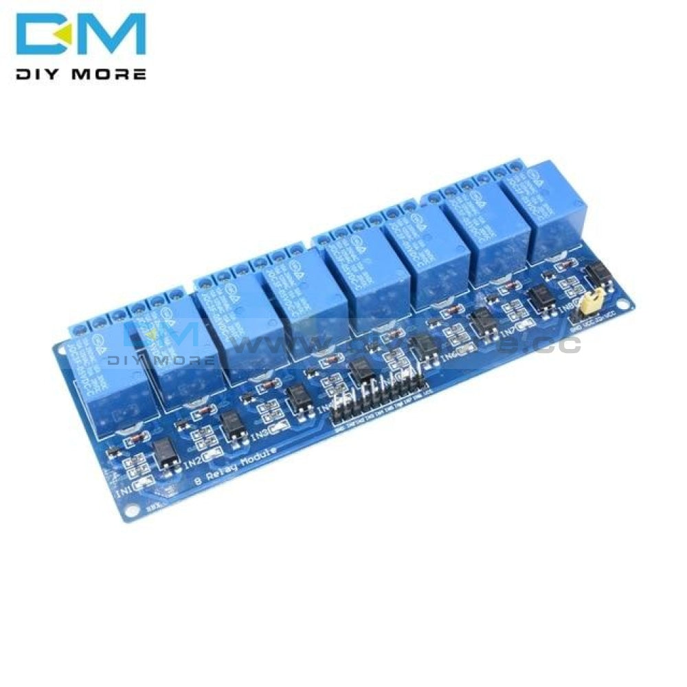
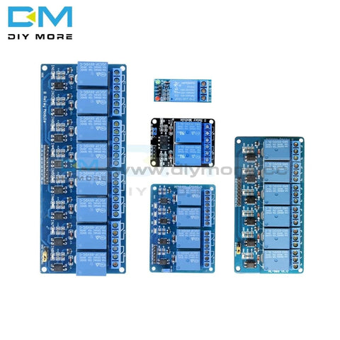 Translation missing: en.products.product.regular_price $4.99{"id":4896534233159,"title":"DC 24V 4 Channel Relay Control Switch RS485\/TTL Anti-reverse Connection Module","handle":"dc-24v-4-channel-relay-control-switch-rs485-ttl-anti-reverse-connection-module","description":"\u003cdiv data-mce-fragment=\"1\"\u003e\u003cspan lang=\"en\" data-mce-fragment=\"1\"\u003e\u003cstrong data-mce-fragment=\"1\"\u003eOverview:\u003c\/strong\u003e\u003c\/span\u003e\u003c\/div\u003e\n\u003cdiv data-mce-fragment=\"1\"\u003e\n\u003cul\u003e\n\u003cli\u003e\u003cspan lang=\"en\" data-mce-fragment=\"1\"\u003eElsay four-way Modbus relay module is equipped with mature and stable 8-bit MCU and RS485 level communication chip. Using standard MODBUS RTU format RS485 communication protocol, it can realize 4 input signal detection and 4 relay output, which can be used for digital detection or power control occasions.\u003c\/span\u003e\u003c\/li\u003e\n\u003c\/ul\u003e\n\u003cspan lang=\"en\" data-mce-fragment=\"1\"\u003e\u003cspan lang=\"en\" data-mce-fragment=\"1\"\u003e\u003cstrong data-mce-fragment=\"1\"\u003eFeatures:\u003c\/strong\u003e\u003cbr data-mce-fragment=\"1\"\u003e\u003c\/span\u003e\u003c\/span\u003e\n\u003cul\u003e\n\u003cli\u003e\u003cspan lang=\"en\" data-mce-fragment=\"1\"\u003eOnboard mature and stable 8bit MCU and MAX485 level conversion chip;\u003c\/span\u003e\u003c\/li\u003e\n\u003cli\u003e\u003cspan lang=\"en\" data-mce-fragment=\"1\"\u003eCommunication protocol: support standard Modbus RTU protocol;\u003c\/span\u003e\u003c\/li\u003e\n\u003cli\u003e\u003cspan lang=\"en\" data-mce-fragment=\"1\"\u003eCommunication interface: support RS485\/TTL UART interface;\u003c\/span\u003e\u003c\/li\u003e\n\u003cli\u003e\u003cspan lang=\"en\" data-mce-fragment=\"1\"\u003eCommunication baud rate: 4800\/9600\/19200, the default is 9600bps, and it supports power-off save;\u003c\/span\u003e\u003c\/li\u003e\n\u003cli\u003e\u003cspan lang=\"en\" data-mce-fragment=\"1\"\u003eOptocoupler input signal range: DC3.3-30V (this input cannot be used for relay control);\u003c\/span\u003e\u003c\/li\u003e\n\u003cli\u003e\u003cspan lang=\"en\" data-mce-fragment=\"1\"\u003eOutput signal: relay switch signal, support manual, flash off, flash off mode, flash off\/flash off delay base is 0.1S, the maximum flash off\/flash off time can be set to 0xFFFF*0.1S=6553.5S;\u003c\/span\u003e\u003c\/li\u003e\n\u003cli\u003e\u003cspan lang=\"en\" data-mce-fragment=\"1\"\u003eDevice address: range 1-255, default 255, support power-off save;\u003c\/span\u003e\u003c\/li\u003e\n\u003cli\u003e\u003cspan lang=\"en\" data-mce-fragment=\"1\"\u003eThe baud rate, input signal, relay status, and device address can be read using software\/commands;\u003c\/span\u003e\u003c\/li\u003e\n\u003cli\u003e\u003cspan lang=\"en\" data-mce-fragment=\"1\"\u003eThere are 4 5V, 10A\/250V AC 10A\/30V DC relays on board, which can be activated continuously for 100,000 times, with diode effusion protection, and short response time;\u003c\/span\u003e\u003c\/li\u003e\n\u003cli\u003e\u003cspan lang=\"en\" data-mce-fragment=\"1\"\u003eOn-board relay switch indicator;\u003c\/span\u003e\u003c\/li\u003e\n\u003cli\u003e\u003cspan lang=\"en\" data-mce-fragment=\"1\"\u003ePower supply voltage: DC7-24V, support DC socket\/5.08mm terminal power supply, with input anti-reverse protection;\u003c\/span\u003e\u003c\/li\u003e\n\u003c\/ul\u003e\n\u003c\/div\u003e\n\u003cdiv data-mce-fragment=\"1\"\u003e\u003cspan data-mce-fragment=\"1\"\u003e\u003cstrong data-mce-fragment=\"1\"\u003e\u003cspan lang=\"en\" data-mce-fragment=\"1\"\u003e\u003cspan title=\"\" data-mce-fragment=\"1\"\u003eHardware introduction and description\u003c\/span\u003e\u003c\/span\u003e\u003c\/strong\u003e\u003c\/span\u003e\u003c\/div\u003e\n\u003cdiv data-mce-fragment=\"1\"\u003e\u003cspan lang=\"en\" data-mce-fragment=\"1\"\u003e\u003cspan title=\"\" data-mce-fragment=\"1\"\u003eBoard size\u003c\/span\u003e\u003c\/span\u003e\u003c\/div\u003e\n\u003cdiv data-mce-fragment=\"1\"\u003e\u003cspan lang=\"en\" data-mce-fragment=\"1\"\u003e\u003cspan title=\"\" data-mce-fragment=\"1\"\u003e\u003cimg src=\"https:\/\/pg-cdn-a2.datacaciques.com\/00\/NDAy\/20\/10\/27\/759miw180130a6g1\/f50580d1c231c450.jpg\" data-mce-fragment=\"1\" data-mce-src=\"https:\/\/pg-cdn-a2.datacaciques.com\/00\/NDAy\/20\/10\/27\/759miw180130a6g1\/f50580d1c231c450.jpg\"\u003e\u003c\/span\u003e\u003c\/span\u003e\u003c\/div\u003e\n\u003cdiv data-mce-fragment=\"1\"\u003e\u003cspan lang=\"en\" data-mce-fragment=\"1\"\u003e\u003cspan title=\"\" data-mce-fragment=\"1\"\u003eInterface introduction\u003c\/span\u003e\u003c\/span\u003e\u003c\/div\u003e\n\u003cdiv data-mce-fragment=\"1\"\u003e\u003cspan lang=\"en\" data-mce-fragment=\"1\"\u003e\u003cspan title=\"\" data-mce-fragment=\"1\"\u003e\u003cimg src=\"https:\/\/pg-cdn-a2.datacaciques.com\/00\/NDAy\/20\/10\/27\/759miw180130a6g1\/4bc7a5d2ad0c45a2.jpg\" data-mce-fragment=\"1\" data-mce-src=\"https:\/\/pg-cdn-a2.datacaciques.com\/00\/NDAy\/20\/10\/27\/759miw180130a6g1\/4bc7a5d2ad0c45a2.jpg\"\u003e\u003c\/span\u003e\u003c\/span\u003e\u003c\/div\u003e\n\u003cdiv data-mce-fragment=\"1\"\u003e\n\u003cul\u003e\n\u003cli\u003e\u003cspan lang=\"en\" data-mce-fragment=\"1\"\u003e\u003cspan title=\"\" data-mce-fragment=\"1\"\u003eDC-005 socket: DC7-24V power input socket;\u003c\/span\u003e\u003c\/span\u003e\u003c\/li\u003e\n\u003cli\u003e\u003cspan lang=\"en\" data-mce-fragment=\"1\"\u003e\u003cspan title=\"\" data-mce-fragment=\"1\"\u003eVCC, GND: DC7-24V 5.08mm power input terminal;\u003c\/span\u003e\u003c\/span\u003e\u003c\/li\u003e\n\u003cli\u003e\u003cspan lang=\"en\" data-mce-fragment=\"1\"\u003e\u003cspan title=\"\" data-mce-fragment=\"1\"\u003eDC3.3-30V optocoupler signal input:\u003c\/span\u003e\u003c\/span\u003e\u003c\/li\u003e\n\u003cli\u003e\u003cspan lang=\"en\" data-mce-fragment=\"1\"\u003e\u003cspan title=\"\" data-mce-fragment=\"1\"\u003eIN1: Channel 1 positive\u003c\/span\u003e\u003c\/span\u003e\u003c\/li\u003e\n\u003cli\u003e\u003cspan lang=\"en\" data-mce-fragment=\"1\"\u003e\u003cspan title=\"\" data-mce-fragment=\"1\"\u003eIN2: Channel 2 positive\u003c\/span\u003e\u003c\/span\u003e\u003c\/li\u003e\n\u003cli\u003e\u003cspan lang=\"en\" data-mce-fragment=\"1\"\u003e\u003cspan title=\"\" data-mce-fragment=\"1\"\u003eIN3: Channel 3 positive\u003c\/span\u003e\u003c\/span\u003e\u003c\/li\u003e\n\u003cli\u003e\u003cspan lang=\"en\" data-mce-fragment=\"1\"\u003e\u003cspan title=\"\" data-mce-fragment=\"1\"\u003eIN4: Channel 4 positive\u003c\/span\u003e\u003c\/span\u003e\u003c\/li\u003e\n\u003cli\u003e\u003cspan lang=\"en\" data-mce-fragment=\"1\"\u003e\u003cspan title=\"\" data-mce-fragment=\"1\"\u003eGND_IN: Common terminal negative\u003c\/span\u003e\u003c\/span\u003e\u003c\/li\u003e\n\u003cli\u003e\u003cspan lang=\"en\" data-mce-fragment=\"1\"\u003e\u003cspan title=\"\" data-mce-fragment=\"1\"\u003eA+, B-: RS485 communication interface, A+, B- are respectively connected to A+, B- of the external control terminal;\u003c\/span\u003e\u003c\/span\u003e\u003c\/li\u003e\n\u003c\/ul\u003e\n\u003cspan lang=\"en\" data-mce-fragment=\"1\"\u003e\u003cspan lang=\"en\" data-mce-fragment=\"1\"\u003e\u003cspan title=\"\" data-mce-fragment=\"1\"\u003e\u003cstrong\u003eRelay switch signal output:\u003c\/strong\u003e\u003cbr data-mce-fragment=\"1\"\u003e\u003c\/span\u003e\u003c\/span\u003e\u003c\/span\u003e\n\u003cul\u003e\n\u003cli\u003e\u003cspan lang=\"en\" data-mce-fragment=\"1\"\u003e\u003cspan title=\"\" data-mce-fragment=\"1\"\u003eNC: Normally closed terminal, the relay is short-connected with COM before it is closed, and it is suspended after it is closed;\u003c\/span\u003e\u003c\/span\u003e\u003c\/li\u003e\n\u003cli\u003e\u003cspan lang=\"en\" data-mce-fragment=\"1\"\u003e\u003cspan title=\"\" data-mce-fragment=\"1\"\u003eCOM: public end;\u003c\/span\u003e\u003c\/span\u003e\u003c\/li\u003e\n\u003cli\u003e\u003cspan lang=\"en\" data-mce-fragment=\"1\"\u003e\u003cspan title=\"\" data-mce-fragment=\"1\"\u003eNO: Normally open end, the relay is suspended before closing, and shorted to COM after closing.\u003c\/span\u003e\u003c\/span\u003e\u003c\/li\u003e\n\u003cli\u003e\u003cspan lang=\"en\" data-mce-fragment=\"1\"\u003e\u003cspan title=\"\" data-mce-fragment=\"1\"\u003e6, GND, RXD, TXD: TTL level UART communication interface, GND, RXD, TXD are respectively connected to GND, TXD, RXD of the external control terminal;\u003c\/span\u003e\u003c\/span\u003e\u003c\/li\u003e\n\u003c\/ul\u003e\n\u003c\/div\u003e\n\u003cdiv data-mce-fragment=\"1\"\u003e\n\u003cspan lang=\"en\" data-mce-fragment=\"1\"\u003e\u003cspan lang=\"en\" data-mce-fragment=\"1\"\u003e\u003cspan title=\"\" data-mce-fragment=\"1\"\u003e\u003cstrong data-mce-fragment=\"1\"\u003eProduct Parameters:\u003c\/strong\u003e\u003cbr data-mce-fragment=\"1\"\u003e\u003c\/span\u003e\u003c\/span\u003e\u003c\/span\u003e\n\u003cul\u003e\n\u003cli\u003e\u003cspan lang=\"en\" data-mce-fragment=\"1\"\u003e\u003cspan title=\"\" data-mce-fragment=\"1\"\u003eItem name: 4CH Modbus Relay Module \u003c\/span\u003e\u003c\/span\u003e\u003c\/li\u003e\n\u003cli\u003e\u003cspan lang=\"en\" data-mce-fragment=\"1\"\u003e\u003cspan title=\"\" data-mce-fragment=\"1\"\u003eWork voltage:DC 7V~24V\u003c\/span\u003e\u003c\/span\u003e\u003c\/li\u003e\n\u003cli\u003e\u003cspan lang=\"en\" data-mce-fragment=\"1\"\u003e\u003cspan title=\"\" data-mce-fragment=\"1\"\u003eBaud rate:4800\/9600\/19600bps(default 9600bps)\u003c\/span\u003e\u003c\/span\u003e\u003c\/li\u003e\n\u003cli\u003e\u003cspan lang=\"en\" data-mce-fragment=\"1\"\u003e\u003cspan title=\"\" data-mce-fragment=\"1\"\u003eOptocoupler input signal:DC 3.3V~30V\u003c\/span\u003e\u003c\/span\u003e\u003c\/li\u003e\n\u003cli\u003e\u003cspan lang=\"en\" data-mce-fragment=\"1\"\u003e\u003cspan title=\"\" data-mce-fragment=\"1\"\u003eSet address:1~255\u003c\/span\u003e\u003c\/span\u003e\u003c\/li\u003e\n\u003cli\u003e\u003cspan lang=\"en\" data-mce-fragment=\"1\"\u003e\u003cspan title=\"\" data-mce-fragment=\"1\"\u003eRelay contorl mode: ON\/OFF,Delay_ON,Delay_OFF mode\u003c\/span\u003e\u003c\/span\u003e\u003c\/li\u003e\n\u003cli\u003e\u003cspan lang=\"en\" data-mce-fragment=\"1\"\u003e\u003cspan title=\"\" data-mce-fragment=\"1\"\u003eDelay time: 0~6553.5s \u003c\/span\u003e\u003c\/span\u003e\u003c\/li\u003e\n\u003cli\u003e\u003cspan lang=\"en\" data-mce-fragment=\"1\"\u003e\u003cspan title=\"\" data-mce-fragment=\"1\"\u003eLoad: AC 250V 10A or DC 28V 10A\u003c\/span\u003e\u003c\/span\u003e\u003c\/li\u003e\n\u003cli\u003e\u003cspan lang=\"en\" data-mce-fragment=\"1\"\u003e\u003cspan title=\"\" data-mce-fragment=\"1\"\u003eProtocol:Modbus RTU\u003c\/span\u003e\u003c\/span\u003e\u003c\/li\u003e\n\u003cli\u003e\u003cspan lang=\"en\" data-mce-fragment=\"1\"\u003e\u003cspan title=\"\" data-mce-fragment=\"1\"\u003eInterface:RS485\/TTL UART\u003c\/span\u003e\u003c\/span\u003e\u003c\/li\u003e\n\u003cli\u003e\u003cspan lang=\"en\" data-mce-fragment=\"1\"\u003e\u003cspan title=\"\" data-mce-fragment=\"1\"\u003eControl channel: 4channel\u003c\/span\u003e\u003c\/span\u003e\u003c\/li\u003e\n\u003cli\u003e\u003cspan lang=\"en\" data-mce-fragment=\"1\"\u003e\u003cspan title=\"\" data-mce-fragment=\"1\"\u003eOperating Temperature:-20℃~85℃\u003c\/span\u003e\u003c\/span\u003e\u003c\/li\u003e\n\u003cli\u003e\u003cspan lang=\"en\" data-mce-fragment=\"1\"\u003e\u003cspan title=\"\" data-mce-fragment=\"1\"\u003eOperating Humidity:5%~95%RH\u003c\/span\u003e\u003c\/span\u003e\u003c\/li\u003e\n\u003cli\u003e\u003cspan lang=\"en\" data-mce-fragment=\"1\"\u003e\u003cspan title=\"\" data-mce-fragment=\"1\"\u003eModule Size:93*90*20mm\u003c\/span\u003e\u003c\/span\u003e\u003c\/li\u003e\n\u003c\/ul\u003e\n\u003cspan lang=\"en\" data-mce-fragment=\"1\"\u003e\u003cspan lang=\"en\" data-mce-fragment=\"1\"\u003e\u003cspan title=\"\" data-mce-fragment=\"1\"\u003e\u003cimg src=\"https:\/\/pg-cdn-a2.datacaciques.com\/00\/NDAy\/20\/10\/27\/759miw180130a6g1\/5a40dd1349231871.jpg\" data-mce-fragment=\"1\" data-mce-src=\"https:\/\/pg-cdn-a2.datacaciques.com\/00\/NDAy\/20\/10\/27\/759miw180130a6g1\/5a40dd1349231871.jpg\"\u003e\u003cbr data-mce-fragment=\"1\"\u003e\u003cstrong data-mce-fragment=\"1\"\u003eModbus RTU Command:\u003c\/strong\u003e\u003cbr data-mce-fragment=\"1\"\u003e\u003c\/span\u003e\u003c\/span\u003e\u003c\/span\u003e\n\u003cul\u003e\n\u003cli\u003e\u003cspan lang=\"en\" data-mce-fragment=\"1\"\u003e\u003cspan title=\"\" data-mce-fragment=\"1\"\u003eSuppose the device address is 0xFF so return 00 10 00 00 00 01 02 00 FF EB 80 and the 9th btye is device address.\u003c\/span\u003e\u003c\/span\u003e\u003c\/li\u003e\n\u003cli\u003e\u003cspan lang=\"en\" data-mce-fragment=\"1\"\u003e\u003cspan title=\"\" data-mce-fragment=\"1\"\u003eTurn ON CH_1 Relay(Normal Mode):\u003c\/span\u003e\u003c\/span\u003e\u003c\/li\u003e\n\u003cli\u003e\u003cspan lang=\"en\" data-mce-fragment=\"1\"\u003e\u003cspan title=\"\" data-mce-fragment=\"1\"\u003e Send: FF 05 00 00 FF 00 99 E4\u003c\/span\u003e\u003c\/span\u003e\u003c\/li\u003e\n\u003cli\u003e\u003cspan lang=\"en\" data-mce-fragment=\"1\"\u003e\u003cspan title=\"\" data-mce-fragment=\"1\"\u003e Return: FF 05 00 00 FF 00 99 E4\u003c\/span\u003e\u003c\/span\u003e\u003c\/li\u003e\n\u003cli\u003e\u003cspan lang=\"en\" data-mce-fragment=\"1\"\u003e\u003cspan title=\"\" data-mce-fragment=\"1\"\u003e Note_1:The 3rd and 4th byte are relay addresses.So it can be 0x0000,0x0001,0x0002,0x0003.\u003c\/span\u003e\u003c\/span\u003e\u003c\/li\u003e\n\u003cli\u003e\u003cspan lang=\"en\" data-mce-fragment=\"1\"\u003e\u003cspan title=\"\" data-mce-fragment=\"1\"\u003e Note_2:The 5th and 6th byte are relay data.0xFF00 means turn ON relay and 0x0000 means turn OFF relay.\u003c\/span\u003e\u003c\/span\u003e\u003c\/li\u003e\n\u003cli\u003e\u003cspan lang=\"en\" data-mce-fragment=\"1\"\u003e\u003cspan title=\"\" data-mce-fragment=\"1\"\u003eTurn OFF CH_1 Relay(Normal Mode):\u003c\/span\u003e\u003c\/span\u003e\u003c\/li\u003e\n\u003cli\u003e\u003cspan lang=\"en\" data-mce-fragment=\"1\"\u003e\u003cspan title=\"\" data-mce-fragment=\"1\"\u003e Send: FF 05 00 00 00 00 D8 14\u003c\/span\u003e\u003c\/span\u003e\u003c\/li\u003e\n\u003cli\u003e\u003cspan lang=\"en\" data-mce-fragment=\"1\"\u003e\u003cspan title=\"\" data-mce-fragment=\"1\"\u003e Return: FF 05 00 00 00 00 D8 14\u003c\/span\u003e\u003c\/span\u003e\u003c\/li\u003e\n\u003cli\u003e\u003cspan lang=\"en\" data-mce-fragment=\"1\"\u003e\u003cspan title=\"\" data-mce-fragment=\"1\"\u003eTurn ON CH_2 Relay(Normal Mode):\u003c\/span\u003e\u003c\/span\u003e\u003c\/li\u003e\n\u003cli\u003e\u003cspan lang=\"en\" data-mce-fragment=\"1\"\u003e\u003cspan title=\"\" data-mce-fragment=\"1\"\u003e Send: FF 05 00 01 FF 00 C8 24\u003c\/span\u003e\u003c\/span\u003e\u003c\/li\u003e\n\u003cli\u003e\u003cspan lang=\"en\" data-mce-fragment=\"1\"\u003e\u003cspan title=\"\" data-mce-fragment=\"1\"\u003e Return: FF 05 00 01 FF 00 C8 24\u003c\/span\u003e\u003c\/span\u003e\u003c\/li\u003e\n\u003cli\u003e\u003cspan lang=\"en\" data-mce-fragment=\"1\"\u003e\u003cspan title=\"\" data-mce-fragment=\"1\"\u003eTurn OFF CH_2 Relay(Normal Mode):\u003c\/span\u003e\u003c\/span\u003e\u003c\/li\u003e\n\u003cli\u003e\u003cspan lang=\"en\" data-mce-fragment=\"1\"\u003e\u003cspan title=\"\" data-mce-fragment=\"1\"\u003e Send: FF 05 00 01 00 00 89 D4\u003c\/span\u003e\u003c\/span\u003e\u003c\/li\u003e\n\u003cli\u003e\u003cspan lang=\"en\" data-mce-fragment=\"1\"\u003e\u003cspan title=\"\" data-mce-fragment=\"1\"\u003e Return: FF 05 00 01 00 00 89 D4\u003c\/span\u003e\u003c\/span\u003e\u003c\/li\u003e\n\u003cli\u003e\u003cspan lang=\"en\" data-mce-fragment=\"1\"\u003e\u003cspan title=\"\" data-mce-fragment=\"1\"\u003eTurn ON All relays:\u003c\/span\u003e\u003c\/span\u003e\u003c\/li\u003e\n\u003cli\u003e\u003cspan lang=\"en\" data-mce-fragment=\"1\"\u003e\u003cspan title=\"\" data-mce-fragment=\"1\"\u003e Send: FF 0F 00 00 00 08 01 FF 30 1D\u003c\/span\u003e\u003c\/span\u003e\u003c\/li\u003e\n\u003cli\u003e\u003cspan lang=\"en\" data-mce-fragment=\"1\"\u003e\u003cspan title=\"\" data-mce-fragment=\"1\"\u003e Return: FF 0F 00 00 00 08 41 D3\u003c\/span\u003e\u003c\/span\u003e\u003c\/li\u003e\n\u003cli\u003e\u003cspan lang=\"en\" data-mce-fragment=\"1\"\u003e\u003cspan title=\"\" data-mce-fragment=\"1\"\u003eTurn OFF All relays:\u003c\/span\u003e\u003c\/span\u003e\u003c\/li\u003e\n\u003cli\u003e\u003cspan lang=\"en\" data-mce-fragment=\"1\"\u003e\u003cspan title=\"\" data-mce-fragment=\"1\"\u003e Send: FF 0F 00 00 00 08 01 00 70 5D\u003c\/span\u003e\u003c\/span\u003e\u003c\/li\u003e\n\u003cli\u003e\u003cspan lang=\"en\" data-mce-fragment=\"1\"\u003e\u003cspan title=\"\" data-mce-fragment=\"1\"\u003e Return: FF 0F 00 00 00 08 41 D3\u003c\/span\u003e\u003c\/span\u003e\u003c\/li\u003e\n\u003cli\u003e\u003cspan lang=\"en\" data-mce-fragment=\"1\"\u003e\u003cspan title=\"\" data-mce-fragment=\"1\"\u003eSet device address to 0x01:\u003c\/span\u003e\u003c\/span\u003e\u003c\/li\u003e\n\u003cli\u003e\u003cspan lang=\"en\" data-mce-fragment=\"1\"\u003e\u003cspan title=\"\" data-mce-fragment=\"1\"\u003e Send: 00 10 00 00 00 01 02 00 01 6A 00\u003c\/span\u003e\u003c\/span\u003e\u003c\/li\u003e\n\u003cli\u003e\u003cspan lang=\"en\" data-mce-fragment=\"1\"\u003e\u003cspan title=\"\" data-mce-fragment=\"1\"\u003e Return: 00 10 00 00 00 01 02 00 01 6A 00\u003c\/span\u003e\u003c\/span\u003e\u003c\/li\u003e\n\u003cli\u003e\u003cspan lang=\"en\" data-mce-fragment=\"1\"\u003e\u003cspan title=\"\" data-mce-fragment=\"1\"\u003e Note: The 9th btye is device address.\u003c\/span\u003e\u003c\/span\u003e\u003c\/li\u003e\n\u003cli\u003e\u003cspan lang=\"en\" data-mce-fragment=\"1\"\u003e\u003cspan title=\"\" data-mce-fragment=\"1\"\u003eSet device address to 0xFF:\u003c\/span\u003e\u003c\/span\u003e\u003c\/li\u003e\n\u003cli\u003e\u003cspan lang=\"en\" data-mce-fragment=\"1\"\u003e\u003cspan title=\"\" data-mce-fragment=\"1\"\u003e Send: 00 10 00 00 00 01 02 00 FF EB 80\u003c\/span\u003e\u003c\/span\u003e\u003c\/li\u003e\n\u003cli\u003e\u003cspan lang=\"en\" data-mce-fragment=\"1\"\u003e\u003cspan title=\"\" data-mce-fragment=\"1\"\u003e Return: 00 10 00 00 00 01 02 00 FF EB 80\u003c\/span\u003e\u003c\/span\u003e\u003c\/li\u003e\n\u003cli\u003e\u003cspan lang=\"en\" data-mce-fragment=\"1\"\u003e\u003cspan title=\"\" data-mce-fragment=\"1\"\u003eRead device address:\u003c\/span\u003e\u003c\/span\u003e\u003c\/li\u003e\n\u003cli\u003e\u003cspan lang=\"en\" data-mce-fragment=\"1\"\u003e\u003cspan title=\"\" data-mce-fragment=\"1\"\u003e Send: 00 03 00 00 00 01 85 DB\u003c\/span\u003e\u003c\/span\u003e\u003c\/li\u003e\n\u003cli\u003e\u003cspan lang=\"en\" data-mce-fragment=\"1\"\u003e\u003cspan title=\"\" data-mce-fragment=\"1\"\u003e Return: 00 03 02 00 FF C5 C4\u003c\/span\u003e\u003c\/span\u003e\u003c\/li\u003e\n\u003cli\u003e\u003cspan lang=\"en\" data-mce-fragment=\"1\"\u003e\u003cspan title=\"\" data-mce-fragment=\"1\"\u003e Note: The 5th btye is device address.\u003c\/span\u003e\u003c\/span\u003e\u003c\/li\u003e\n\u003cli\u003e\u003cspan lang=\"en\" data-mce-fragment=\"1\"\u003e\u003cspan title=\"\" data-mce-fragment=\"1\"\u003eRead relay status:\u003c\/span\u003e\u003c\/span\u003e\u003c\/li\u003e\n\u003cli\u003e\u003cspan lang=\"en\" data-mce-fragment=\"1\"\u003e\u003cspan title=\"\" data-mce-fragment=\"1\"\u003e Send: FF 01 00 00 00 08 28 12\u003c\/span\u003e\u003c\/span\u003e\u003c\/li\u003e\n\u003cli\u003e\u003cspan lang=\"en\" data-mce-fragment=\"1\"\u003e\u003cspan title=\"\" data-mce-fragment=\"1\"\u003e Return: FF 01 01 01 A1 A0\u003c\/span\u003e\u003c\/span\u003e\u003c\/li\u003e\n\u003cli\u003e\u003cspan lang=\"en\" data-mce-fragment=\"1\"\u003e\u003cspan title=\"\" data-mce-fragment=\"1\"\u003e Note:The 4th means which one relay.0 means OFF and 1 means ON.\u003c\/span\u003e\u003c\/span\u003e\u003c\/li\u003e\n\u003cli\u003e\u003cspan lang=\"en\" data-mce-fragment=\"1\"\u003e\u003cspan title=\"\" data-mce-fragment=\"1\"\u003eRead optocoupler input staturs:\u003c\/span\u003e\u003c\/span\u003e\u003c\/li\u003e\n\u003cli\u003e\u003cspan lang=\"en\" data-mce-fragment=\"1\"\u003e\u003cspan title=\"\" data-mce-fragment=\"1\"\u003e Send: FF 02 00 00 00 08 6C 12\u003c\/span\u003e\u003c\/span\u003e\u003c\/li\u003e\n\u003cli\u003e\u003cspan lang=\"en\" data-mce-fragment=\"1\"\u003e\u003cspan title=\"\" data-mce-fragment=\"1\"\u003e Return: FF 02 01 01 51 A0\u003c\/span\u003e\u003c\/span\u003e\u003c\/li\u003e\n\u003cli\u003e\u003cspan lang=\"en\" data-mce-fragment=\"1\"\u003e\u003cspan title=\"\" data-mce-fragment=\"1\"\u003e Note:The 4th means which one input.0 means low level signal input and 1 means high level signal input.\u003c\/span\u003e\u003c\/span\u003e\u003c\/li\u003e\n\u003cli\u003e\u003cspan lang=\"en\" data-mce-fragment=\"1\"\u003e\u003cspan title=\"\" data-mce-fragment=\"1\"\u003eSet baud rate 4800bps:\u003c\/span\u003e\u003c\/span\u003e\u003c\/li\u003e\n\u003cli\u003e\u003cspan lang=\"en\" data-mce-fragment=\"1\"\u003e\u003cspan title=\"\" data-mce-fragment=\"1\"\u003e Send: FF 10 03 E9 00 01 02 00 02 4A 0C\u003c\/span\u003e\u003c\/span\u003e\u003c\/li\u003e\n\u003cli\u003e\u003cspan lang=\"en\" data-mce-fragment=\"1\"\u003e\u003cspan title=\"\" data-mce-fragment=\"1\"\u003e Return: FF 10 03 E9 00 01 C5 A7\u003c\/span\u003e\u003c\/span\u003e\u003c\/li\u003e\n\u003cli\u003e\u003cspan lang=\"en\" data-mce-fragment=\"1\"\u003e\u003cspan title=\"\" data-mce-fragment=\"1\"\u003e Note:The 9th btye is baud rate value.0x02 is 4800bps.0x03 is 9600bps.0x04 is 19200bps.\u003c\/span\u003e\u003c\/span\u003e\u003c\/li\u003e\n\u003cli\u003e\u003cspan lang=\"en\" data-mce-fragment=\"1\"\u003e\u003cspan title=\"\" data-mce-fragment=\"1\"\u003eSet baud rate 9600bps:\u003c\/span\u003e\u003c\/span\u003e\u003c\/li\u003e\n\u003cli\u003e\u003cspan lang=\"en\" data-mce-fragment=\"1\"\u003e\u003cspan title=\"\" data-mce-fragment=\"1\"\u003e Send: FF 10 03 E9 00 01 02 00 03 8B CC\u003c\/span\u003e\u003c\/span\u003e\u003c\/li\u003e\n\u003cli\u003e\u003cspan lang=\"en\" data-mce-fragment=\"1\"\u003e\u003cspan title=\"\" data-mce-fragment=\"1\"\u003e Return: FF 10 03 E9 00 01 C5 A7\u003c\/span\u003e\u003c\/span\u003e\u003c\/li\u003e\n\u003cli\u003e\u003cspan lang=\"en\" data-mce-fragment=\"1\"\u003e\u003cspan title=\"\" data-mce-fragment=\"1\"\u003eSet baud rate 19200bps:\u003c\/span\u003e\u003c\/span\u003e\u003c\/li\u003e\n\u003cli\u003e\u003cspan lang=\"en\" data-mce-fragment=\"1\"\u003e\u003cspan title=\"\" data-mce-fragment=\"1\"\u003e Send: FF 10 03 E9 00 01 02 00 04 CA 0E\u003c\/span\u003e\u003c\/span\u003e\u003c\/li\u003e\n\u003cli\u003e\u003cspan lang=\"en\" data-mce-fragment=\"1\"\u003e\u003cspan title=\"\" data-mce-fragment=\"1\"\u003e Return: FF 10 03 E9 00 01 C5 A7\u003c\/span\u003e\u003c\/span\u003e\u003c\/li\u003e\n\u003cli\u003e\u003cspan lang=\"en\" data-mce-fragment=\"1\"\u003e\u003cspan title=\"\" data-mce-fragment=\"1\"\u003eTurn ON CH_1 Relay(2S Flashing Mode):\u003c\/span\u003e\u003c\/span\u003e\u003c\/li\u003e\n\u003cli\u003e\u003cspan lang=\"en\" data-mce-fragment=\"1\"\u003e\u003cspan title=\"\" data-mce-fragment=\"1\"\u003e Send: FF 10 00 03 00 02 04 00 04 00 14 C5 9F\u003c\/span\u003e\u003c\/span\u003e\u003c\/li\u003e\n\u003cli\u003e\u003cspan lang=\"en\" data-mce-fragment=\"1\"\u003e\u003cspan title=\"\" data-mce-fragment=\"1\"\u003e Return: FF 10 00 03 00 02 A4 16\u003c\/span\u003e\u003c\/span\u003e\u003c\/li\u003e\n\u003cli\u003e\u003cspan lang=\"en\" data-mce-fragment=\"1\"\u003e\u003cspan title=\"\" data-mce-fragment=\"1\"\u003e Note_1:The 3rd and 4th byte are relay addresses.So CH1~CH4 can be 0x0003,0x0008,0x000D,0x0012.\u003c\/span\u003e\u003c\/span\u003e\u003c\/li\u003e\n\u003cli\u003e\u003cspan lang=\"en\" data-mce-fragment=\"1\"\u003e\u003cspan title=\"\" data-mce-fragment=\"1\"\u003e Note_2:The 10th and 11th byte are delay time in second.The minimum delay time is 0.1s.Relay will OFF after delay time.So the delay time in this command is : 0x0014*0.1=2S.\u003c\/span\u003e\u003c\/span\u003e\u003c\/li\u003e\n\u003cli\u003e\u003cspan lang=\"en\" data-mce-fragment=\"1\"\u003e\u003cspan title=\"\" data-mce-fragment=\"1\"\u003eTurn OFF CH_1 Relay(3S Flashing Mode):\u003c\/span\u003e\u003c\/span\u003e\u003c\/li\u003e\n\u003cli\u003e\u003cspan lang=\"en\" data-mce-fragment=\"1\"\u003e\u003cspan title=\"\" data-mce-fragment=\"1\"\u003e Send: FF 10 00 03 00 02 04 00 02 00 1E A5 99\u003c\/span\u003e\u003c\/span\u003e\u003c\/li\u003e\n\u003cli\u003e\u003cspan lang=\"en\" data-mce-fragment=\"1\"\u003e\u003cspan title=\"\" data-mce-fragment=\"1\"\u003e Return: FF 10 00 03 00 02 A4 16\u003c\/span\u003e\u003c\/span\u003e\u003c\/li\u003e\n\u003cli\u003e\u003cspan lang=\"en\" data-mce-fragment=\"1\"\u003e\u003cspan title=\"\" data-mce-fragment=\"1\"\u003e Note:Relay will ON after delay time.So the delay time in this command is : 0x001E*0.1=3S.\u003c\/span\u003e\u003c\/span\u003e\u003c\/li\u003e\n\u003c\/ul\u003e\n\u003cspan lang=\"en\" data-mce-fragment=\"1\"\u003e\u003cspan lang=\"en\" data-mce-fragment=\"1\"\u003e\u003cspan title=\"\" data-mce-fragment=\"1\"\u003e\u003cimg src=\"https:\/\/pg-cdn-a2.datacaciques.com\/00\/NDAy\/20\/10\/27\/759miw180130a6g1\/b4e1c2017abb1ec6.jpg\" data-mce-fragment=\"1\" data-mce-src=\"https:\/\/pg-cdn-a2.datacaciques.com\/00\/NDAy\/20\/10\/27\/759miw180130a6g1\/b4e1c2017abb1ec6.jpg\"\u003e\u003cbr data-mce-fragment=\"1\"\u003e\u003cstrong data-mce-fragment=\"1\"\u003ePackage Include:\u003c\/strong\u003e\u003cbr data-mce-fragment=\"1\"\u003e\u003c\/span\u003e\u003c\/span\u003e\u003c\/span\u003e\n\u003cul\u003e\n\u003cli\u003e\u003cspan lang=\"en\" data-mce-fragment=\"1\"\u003e\u003cspan title=\"\" data-mce-fragment=\"1\"\u003e 1PC 4CH Modbus Relay Module \u003c\/span\u003e\u003c\/span\u003e\u003c\/li\u003e\n\u003c\/ul\u003e\n\u003c\/div\u003e\n\u003cdiv data-mce-fragment=\"1\"\u003e\u003cspan lang=\"en\" data-mce-fragment=\"1\"\u003e\u003cspan title=\"\" data-mce-fragment=\"1\"\u003e \u003c\/span\u003e\u003c\/span\u003e\u003c\/div\u003e","published_at":"2020-10-29T16:43:18+08:00","created_at":"2020-10-28T12:04:09+08:00","vendor":"DIYMORE","type":"","tags":[],"price":1099,"price_min":1099,"price_max":1099,"available":true,"price_varies":false,"compare_at_price":null,"compare_at_price_min":0,"compare_at_price_max":0,"compare_at_price_varies":false,"variants":[{"id":32644275765319,"title":"Default Title","option1":"Default Title","option2":null,"option3":null,"sku":"XM0006","requires_shipping":true,"taxable":false,"featured_image":null,"available":true,"name":"DC 24V 4 Channel Relay Control Switch RS485\/TTL Anti-reverse Connection Module","public_title":null,"options":["Default Title"],"price":1099,"weight":0,"compare_at_price":null,"inventory_management":"shopify","barcode":"","requires_selling_plan":false,"selling_plan_allocations":[],"quantity_rule":{"min":1,"max":null,"increment":1}}],"images":["\/\/www.diymore.cc\/cdn\/shop\/products\/3_c1c2716b-4e56-4778-96d4-eb4ff9c7620a.jpg?v=1603857853","\/\/www.diymore.cc\/cdn\/shop\/products\/5_ff208254-a902-4d04-93e4-bce5ea8eb512.jpg?v=1603857854","\/\/www.diymore.cc\/cdn\/shop\/products\/4_0b281e6a-ef90-4366-8a24-d9a167cf31ca.jpg?v=1603857854","\/\/www.diymore.cc\/cdn\/shop\/products\/1_968bb946-a0f2-4ed7-8618-2ab8b7fa26f9.jpg?v=1603857854","\/\/www.diymore.cc\/cdn\/shop\/products\/2_5f6abbf8-5697-4e69-9c60-03559cfb6029.jpg?v=1603857854"],"featured_image":"\/\/www.diymore.cc\/cdn\/shop\/products\/3_c1c2716b-4e56-4778-96d4-eb4ff9c7620a.jpg?v=1603857853","options":["Title"],"media":[{"alt":null,"id":7652174987335,"position":1,"preview_image":{"aspect_ratio":1.0,"height":1000,"width":1000,"src":"\/\/www.diymore.cc\/cdn\/shop\/products\/3_c1c2716b-4e56-4778-96d4-eb4ff9c7620a.jpg?v=1603857853"},"aspect_ratio":1.0,"height":1000,"media_type":"image","src":"\/\/www.diymore.cc\/cdn\/shop\/products\/3_c1c2716b-4e56-4778-96d4-eb4ff9c7620a.jpg?v=1603857853","width":1000},{"alt":null,"id":7652175020103,"position":2,"preview_image":{"aspect_ratio":1.0,"height":1000,"width":1000,"src":"\/\/www.diymore.cc\/cdn\/shop\/products\/5_ff208254-a902-4d04-93e4-bce5ea8eb512.jpg?v=1603857854"},"aspect_ratio":1.0,"height":1000,"media_type":"image","src":"\/\/www.diymore.cc\/cdn\/shop\/products\/5_ff208254-a902-4d04-93e4-bce5ea8eb512.jpg?v=1603857854","width":1000},{"alt":null,"id":7652175052871,"position":3,"preview_image":{"aspect_ratio":1.0,"height":1000,"width":1000,"src":"\/\/www.diymore.cc\/cdn\/shop\/products\/4_0b281e6a-ef90-4366-8a24-d9a167cf31ca.jpg?v=1603857854"},"aspect_ratio":1.0,"height":1000,"media_type":"image","src":"\/\/www.diymore.cc\/cdn\/shop\/products\/4_0b281e6a-ef90-4366-8a24-d9a167cf31ca.jpg?v=1603857854","width":1000},{"alt":null,"id":7652175085639,"position":4,"preview_image":{"aspect_ratio":1.0,"height":1000,"width":1000,"src":"\/\/www.diymore.cc\/cdn\/shop\/products\/1_968bb946-a0f2-4ed7-8618-2ab8b7fa26f9.jpg?v=1603857854"},"aspect_ratio":1.0,"height":1000,"media_type":"image","src":"\/\/www.diymore.cc\/cdn\/shop\/products\/1_968bb946-a0f2-4ed7-8618-2ab8b7fa26f9.jpg?v=1603857854","width":1000},{"alt":null,"id":7652175118407,"position":5,"preview_image":{"aspect_ratio":1.0,"height":1000,"width":1000,"src":"\/\/www.diymore.cc\/cdn\/shop\/products\/2_5f6abbf8-5697-4e69-9c60-03559cfb6029.jpg?v=1603857854"},"aspect_ratio":1.0,"height":1000,"media_type":"image","src":"\/\/www.diymore.cc\/cdn\/shop\/products\/2_5f6abbf8-5697-4e69-9c60-03559cfb6029.jpg?v=1603857854","width":1000}],"requires_selling_plan":false,"selling_plan_groups":[],"content":"\u003cdiv data-mce-fragment=\"1\"\u003e\u003cspan lang=\"en\" data-mce-fragment=\"1\"\u003e\u003cstrong data-mce-fragment=\"1\"\u003eOverview:\u003c\/strong\u003e\u003c\/span\u003e\u003c\/div\u003e\n\u003cdiv data-mce-fragment=\"1\"\u003e\n\u003cul\u003e\n\u003cli\u003e\u003cspan lang=\"en\" data-mce-fragment=\"1\"\u003eElsay four-way Modbus relay module is equipped with mature and stable 8-bit MCU and RS485 level communication chip. Using standard MODBUS RTU format RS485 communication protocol, it can realize 4 input signal detection and 4 relay output, which can be used for digital detection or power control occasions.\u003c\/span\u003e\u003c\/li\u003e\n\u003c\/ul\u003e\n\u003cspan lang=\"en\" data-mce-fragment=\"1\"\u003e\u003cspan lang=\"en\" data-mce-fragment=\"1\"\u003e\u003cstrong data-mce-fragment=\"1\"\u003eFeatures:\u003c\/strong\u003e\u003cbr data-mce-fragment=\"1\"\u003e\u003c\/span\u003e\u003c\/span\u003e\n\u003cul\u003e\n\u003cli\u003e\u003cspan lang=\"en\" data-mce-fragment=\"1\"\u003eOnboard mature and stable 8bit MCU and MAX485 level conversion chip;\u003c\/span\u003e\u003c\/li\u003e\n\u003cli\u003e\u003cspan lang=\"en\" data-mce-fragment=\"1\"\u003eCommunication protocol: support standard Modbus RTU protocol;\u003c\/span\u003e\u003c\/li\u003e\n\u003cli\u003e\u003cspan lang=\"en\" data-mce-fragment=\"1\"\u003eCommunication interface: support RS485\/TTL UART interface;\u003c\/span\u003e\u003c\/li\u003e\n\u003cli\u003e\u003cspan lang=\"en\" data-mce-fragment=\"1\"\u003eCommunication baud rate: 4800\/9600\/19200, the default is 9600bps, and it supports power-off save;\u003c\/span\u003e\u003c\/li\u003e\n\u003cli\u003e\u003cspan lang=\"en\" data-mce-fragment=\"1\"\u003eOptocoupler input signal range: DC3.3-30V (this input cannot be used for relay control);\u003c\/span\u003e\u003c\/li\u003e\n\u003cli\u003e\u003cspan lang=\"en\" data-mce-fragment=\"1\"\u003eOutput signal: relay switch signal, support manual, flash off, flash off mode, flash off\/flash off delay base is 0.1S, the maximum flash off\/flash off time can be set to 0xFFFF*0.1S=6553.5S;\u003c\/span\u003e\u003c\/li\u003e\n\u003cli\u003e\u003cspan lang=\"en\" data-mce-fragment=\"1\"\u003eDevice address: range 1-255, default 255, support power-off save;\u003c\/span\u003e\u003c\/li\u003e\n\u003cli\u003e\u003cspan lang=\"en\" data-mce-fragment=\"1\"\u003eThe baud rate, input signal, relay status, and device address can be read using software\/commands;\u003c\/span\u003e\u003c\/li\u003e\n\u003cli\u003e\u003cspan lang=\"en\" data-mce-fragment=\"1\"\u003eThere are 4 5V, 10A\/250V AC 10A\/30V DC relays on board, which can be activated continuously for 100,000 times, with diode effusion protection, and short response time;\u003c\/span\u003e\u003c\/li\u003e\n\u003cli\u003e\u003cspan lang=\"en\" data-mce-fragment=\"1\"\u003eOn-board relay switch indicator;\u003c\/span\u003e\u003c\/li\u003e\n\u003cli\u003e\u003cspan lang=\"en\" data-mce-fragment=\"1\"\u003ePower supply voltage: DC7-24V, support DC socket\/5.08mm terminal power supply, with input anti-reverse protection;\u003c\/span\u003e\u003c\/li\u003e\n\u003c\/ul\u003e\n\u003c\/div\u003e\n\u003cdiv data-mce-fragment=\"1\"\u003e\u003cspan data-mce-fragment=\"1\"\u003e\u003cstrong data-mce-fragment=\"1\"\u003e\u003cspan lang=\"en\" data-mce-fragment=\"1\"\u003e\u003cspan title=\"\" data-mce-fragment=\"1\"\u003eHardware introduction and description\u003c\/span\u003e\u003c\/span\u003e\u003c\/strong\u003e\u003c\/span\u003e\u003c\/div\u003e\n\u003cdiv data-mce-fragment=\"1\"\u003e\u003cspan lang=\"en\" data-mce-fragment=\"1\"\u003e\u003cspan title=\"\" data-mce-fragment=\"1\"\u003eBoard size\u003c\/span\u003e\u003c\/span\u003e\u003c\/div\u003e\n\u003cdiv data-mce-fragment=\"1\"\u003e\u003cspan lang=\"en\" data-mce-fragment=\"1\"\u003e\u003cspan title=\"\" data-mce-fragment=\"1\"\u003e\u003cimg src=\"https:\/\/pg-cdn-a2.datacaciques.com\/00\/NDAy\/20\/10\/27\/759miw180130a6g1\/f50580d1c231c450.jpg\" data-mce-fragment=\"1\" data-mce-src=\"https:\/\/pg-cdn-a2.datacaciques.com\/00\/NDAy\/20\/10\/27\/759miw180130a6g1\/f50580d1c231c450.jpg\"\u003e\u003c\/span\u003e\u003c\/span\u003e\u003c\/div\u003e\n\u003cdiv data-mce-fragment=\"1\"\u003e\u003cspan lang=\"en\" data-mce-fragment=\"1\"\u003e\u003cspan title=\"\" data-mce-fragment=\"1\"\u003eInterface introduction\u003c\/span\u003e\u003c\/span\u003e\u003c\/div\u003e\n\u003cdiv data-mce-fragment=\"1\"\u003e\u003cspan lang=\"en\" data-mce-fragment=\"1\"\u003e\u003cspan title=\"\" data-mce-fragment=\"1\"\u003e\u003cimg src=\"https:\/\/pg-cdn-a2.datacaciques.com\/00\/NDAy\/20\/10\/27\/759miw180130a6g1\/4bc7a5d2ad0c45a2.jpg\" data-mce-fragment=\"1\" data-mce-src=\"https:\/\/pg-cdn-a2.datacaciques.com\/00\/NDAy\/20\/10\/27\/759miw180130a6g1\/4bc7a5d2ad0c45a2.jpg\"\u003e\u003c\/span\u003e\u003c\/span\u003e\u003c\/div\u003e\n\u003cdiv data-mce-fragment=\"1\"\u003e\n\u003cul\u003e\n\u003cli\u003e\u003cspan lang=\"en\" data-mce-fragment=\"1\"\u003e\u003cspan title=\"\" data-mce-fragment=\"1\"\u003eDC-005 socket: DC7-24V power input socket;\u003c\/span\u003e\u003c\/span\u003e\u003c\/li\u003e\n\u003cli\u003e\u003cspan lang=\"en\" data-mce-fragment=\"1\"\u003e\u003cspan title=\"\" data-mce-fragment=\"1\"\u003eVCC, GND: DC7-24V 5.08mm power input terminal;\u003c\/span\u003e\u003c\/span\u003e\u003c\/li\u003e\n\u003cli\u003e\u003cspan lang=\"en\" data-mce-fragment=\"1\"\u003e\u003cspan title=\"\" data-mce-fragment=\"1\"\u003eDC3.3-30V optocoupler signal input:\u003c\/span\u003e\u003c\/span\u003e\u003c\/li\u003e\n\u003cli\u003e\u003cspan lang=\"en\" data-mce-fragment=\"1\"\u003e\u003cspan title=\"\" data-mce-fragment=\"1\"\u003eIN1: Channel 1 positive\u003c\/span\u003e\u003c\/span\u003e\u003c\/li\u003e\n\u003cli\u003e\u003cspan lang=\"en\" data-mce-fragment=\"1\"\u003e\u003cspan title=\"\" data-mce-fragment=\"1\"\u003eIN2: Channel 2 positive\u003c\/span\u003e\u003c\/span\u003e\u003c\/li\u003e\n\u003cli\u003e\u003cspan lang=\"en\" data-mce-fragment=\"1\"\u003e\u003cspan title=\"\" data-mce-fragment=\"1\"\u003eIN3: Channel 3 positive\u003c\/span\u003e\u003c\/span\u003e\u003c\/li\u003e\n\u003cli\u003e\u003cspan lang=\"en\" data-mce-fragment=\"1\"\u003e\u003cspan title=\"\" data-mce-fragment=\"1\"\u003eIN4: Channel 4 positive\u003c\/span\u003e\u003c\/span\u003e\u003c\/li\u003e\n\u003cli\u003e\u003cspan lang=\"en\" data-mce-fragment=\"1\"\u003e\u003cspan title=\"\" data-mce-fragment=\"1\"\u003eGND_IN: Common terminal negative\u003c\/span\u003e\u003c\/span\u003e\u003c\/li\u003e\n\u003cli\u003e\u003cspan lang=\"en\" data-mce-fragment=\"1\"\u003e\u003cspan title=\"\" data-mce-fragment=\"1\"\u003eA+, B-: RS485 communication interface, A+, B- are respectively connected to A+, B- of the external control terminal;\u003c\/span\u003e\u003c\/span\u003e\u003c\/li\u003e\n\u003c\/ul\u003e\n\u003cspan lang=\"en\" data-mce-fragment=\"1\"\u003e\u003cspan lang=\"en\" data-mce-fragment=\"1\"\u003e\u003cspan title=\"\" data-mce-fragment=\"1\"\u003e\u003cstrong\u003eRelay switch signal output:\u003c\/strong\u003e\u003cbr data-mce-fragment=\"1\"\u003e\u003c\/span\u003e\u003c\/span\u003e\u003c\/span\u003e\n\u003cul\u003e\n\u003cli\u003e\u003cspan lang=\"en\" data-mce-fragment=\"1\"\u003e\u003cspan title=\"\" data-mce-fragment=\"1\"\u003eNC: Normally closed terminal, the relay is short-connected with COM before it is closed, and it is suspended after it is closed;\u003c\/span\u003e\u003c\/span\u003e\u003c\/li\u003e\n\u003cli\u003e\u003cspan lang=\"en\" data-mce-fragment=\"1\"\u003e\u003cspan title=\"\" data-mce-fragment=\"1\"\u003eCOM: public end;\u003c\/span\u003e\u003c\/span\u003e\u003c\/li\u003e\n\u003cli\u003e\u003cspan lang=\"en\" data-mce-fragment=\"1\"\u003e\u003cspan title=\"\" data-mce-fragment=\"1\"\u003eNO: Normally open end, the relay is suspended before closing, and shorted to COM after closing.\u003c\/span\u003e\u003c\/span\u003e\u003c\/li\u003e\n\u003cli\u003e\u003cspan lang=\"en\" data-mce-fragment=\"1\"\u003e\u003cspan title=\"\" data-mce-fragment=\"1\"\u003e6, GND, RXD, TXD: TTL level UART communication interface, GND, RXD, TXD are respectively connected to GND, TXD, RXD of the external control terminal;\u003c\/span\u003e\u003c\/span\u003e\u003c\/li\u003e\n\u003c\/ul\u003e\n\u003c\/div\u003e\n\u003cdiv data-mce-fragment=\"1\"\u003e\n\u003cspan lang=\"en\" data-mce-fragment=\"1\"\u003e\u003cspan lang=\"en\" data-mce-fragment=\"1\"\u003e\u003cspan title=\"\" data-mce-fragment=\"1\"\u003e\u003cstrong data-mce-fragment=\"1\"\u003eProduct Parameters:\u003c\/strong\u003e\u003cbr data-mce-fragment=\"1\"\u003e\u003c\/span\u003e\u003c\/span\u003e\u003c\/span\u003e\n\u003cul\u003e\n\u003cli\u003e\u003cspan lang=\"en\" data-mce-fragment=\"1\"\u003e\u003cspan title=\"\" data-mce-fragment=\"1\"\u003eItem name: 4CH Modbus Relay Module \u003c\/span\u003e\u003c\/span\u003e\u003c\/li\u003e\n\u003cli\u003e\u003cspan lang=\"en\" data-mce-fragment=\"1\"\u003e\u003cspan title=\"\" data-mce-fragment=\"1\"\u003eWork voltage:DC 7V~24V\u003c\/span\u003e\u003c\/span\u003e\u003c\/li\u003e\n\u003cli\u003e\u003cspan lang=\"en\" data-mce-fragment=\"1\"\u003e\u003cspan title=\"\" data-mce-fragment=\"1\"\u003eBaud rate:4800\/9600\/19600bps(default 9600bps)\u003c\/span\u003e\u003c\/span\u003e\u003c\/li\u003e\n\u003cli\u003e\u003cspan lang=\"en\" data-mce-fragment=\"1\"\u003e\u003cspan title=\"\" data-mce-fragment=\"1\"\u003eOptocoupler input signal:DC 3.3V~30V\u003c\/span\u003e\u003c\/span\u003e\u003c\/li\u003e\n\u003cli\u003e\u003cspan lang=\"en\" data-mce-fragment=\"1\"\u003e\u003cspan title=\"\" data-mce-fragment=\"1\"\u003eSet address:1~255\u003c\/span\u003e\u003c\/span\u003e\u003c\/li\u003e\n\u003cli\u003e\u003cspan lang=\"en\" data-mce-fragment=\"1\"\u003e\u003cspan title=\"\" data-mce-fragment=\"1\"\u003eRelay contorl mode: ON\/OFF,Delay_ON,Delay_OFF mode\u003c\/span\u003e\u003c\/span\u003e\u003c\/li\u003e\n\u003cli\u003e\u003cspan lang=\"en\" data-mce-fragment=\"1\"\u003e\u003cspan title=\"\" data-mce-fragment=\"1\"\u003eDelay time: 0~6553.5s \u003c\/span\u003e\u003c\/span\u003e\u003c\/li\u003e\n\u003cli\u003e\u003cspan lang=\"en\" data-mce-fragment=\"1\"\u003e\u003cspan title=\"\" data-mce-fragment=\"1\"\u003eLoad: AC 250V 10A or DC 28V 10A\u003c\/span\u003e\u003c\/span\u003e\u003c\/li\u003e\n\u003cli\u003e\u003cspan lang=\"en\" data-mce-fragment=\"1\"\u003e\u003cspan title=\"\" data-mce-fragment=\"1\"\u003eProtocol:Modbus RTU\u003c\/span\u003e\u003c\/span\u003e\u003c\/li\u003e\n\u003cli\u003e\u003cspan lang=\"en\" data-mce-fragment=\"1\"\u003e\u003cspan title=\"\" data-mce-fragment=\"1\"\u003eInterface:RS485\/TTL UART\u003c\/span\u003e\u003c\/span\u003e\u003c\/li\u003e\n\u003cli\u003e\u003cspan lang=\"en\" data-mce-fragment=\"1\"\u003e\u003cspan title=\"\" data-mce-fragment=\"1\"\u003eControl channel: 4channel\u003c\/span\u003e\u003c\/span\u003e\u003c\/li\u003e\n\u003cli\u003e\u003cspan lang=\"en\" data-mce-fragment=\"1\"\u003e\u003cspan title=\"\" data-mce-fragment=\"1\"\u003eOperating Temperature:-20℃~85℃\u003c\/span\u003e\u003c\/span\u003e\u003c\/li\u003e\n\u003cli\u003e\u003cspan lang=\"en\" data-mce-fragment=\"1\"\u003e\u003cspan title=\"\" data-mce-fragment=\"1\"\u003eOperating Humidity:5%~95%RH\u003c\/span\u003e\u003c\/span\u003e\u003c\/li\u003e\n\u003cli\u003e\u003cspan lang=\"en\" data-mce-fragment=\"1\"\u003e\u003cspan title=\"\" data-mce-fragment=\"1\"\u003eModule Size:93*90*20mm\u003c\/span\u003e\u003c\/span\u003e\u003c\/li\u003e\n\u003c\/ul\u003e\n\u003cspan lang=\"en\" data-mce-fragment=\"1\"\u003e\u003cspan lang=\"en\" data-mce-fragment=\"1\"\u003e\u003cspan title=\"\" data-mce-fragment=\"1\"\u003e\u003cimg src=\"https:\/\/pg-cdn-a2.datacaciques.com\/00\/NDAy\/20\/10\/27\/759miw180130a6g1\/5a40dd1349231871.jpg\" data-mce-fragment=\"1\" data-mce-src=\"https:\/\/pg-cdn-a2.datacaciques.com\/00\/NDAy\/20\/10\/27\/759miw180130a6g1\/5a40dd1349231871.jpg\"\u003e\u003cbr data-mce-fragment=\"1\"\u003e\u003cstrong data-mce-fragment=\"1\"\u003eModbus RTU Command:\u003c\/strong\u003e\u003cbr data-mce-fragment=\"1\"\u003e\u003c\/span\u003e\u003c\/span\u003e\u003c\/span\u003e\n\u003cul\u003e\n\u003cli\u003e\u003cspan lang=\"en\" data-mce-fragment=\"1\"\u003e\u003cspan title=\"\" data-mce-fragment=\"1\"\u003eSuppose the device address is 0xFF so return 00 10 00 00 00 01 02 00 FF EB 80 and the 9th btye is device address.\u003c\/span\u003e\u003c\/span\u003e\u003c\/li\u003e\n\u003cli\u003e\u003cspan lang=\"en\" data-mce-fragment=\"1\"\u003e\u003cspan title=\"\" data-mce-fragment=\"1\"\u003eTurn ON CH_1 Relay(Normal Mode):\u003c\/span\u003e\u003c\/span\u003e\u003c\/li\u003e\n\u003cli\u003e\u003cspan lang=\"en\" data-mce-fragment=\"1\"\u003e\u003cspan title=\"\" data-mce-fragment=\"1\"\u003e Send: FF 05 00 00 FF 00 99 E4\u003c\/span\u003e\u003c\/span\u003e\u003c\/li\u003e\n\u003cli\u003e\u003cspan lang=\"en\" data-mce-fragment=\"1\"\u003e\u003cspan title=\"\" data-mce-fragment=\"1\"\u003e Return: FF 05 00 00 FF 00 99 E4\u003c\/span\u003e\u003c\/span\u003e\u003c\/li\u003e\n\u003cli\u003e\u003cspan lang=\"en\" data-mce-fragment=\"1\"\u003e\u003cspan title=\"\" data-mce-fragment=\"1\"\u003e Note_1:The 3rd and 4th byte are relay addresses.So it can be 0x0000,0x0001,0x0002,0x0003.\u003c\/span\u003e\u003c\/span\u003e\u003c\/li\u003e\n\u003cli\u003e\u003cspan lang=\"en\" data-mce-fragment=\"1\"\u003e\u003cspan title=\"\" data-mce-fragment=\"1\"\u003e Note_2:The 5th and 6th byte are relay data.0xFF00 means turn ON relay and 0x0000 means turn OFF relay.\u003c\/span\u003e\u003c\/span\u003e\u003c\/li\u003e\n\u003cli\u003e\u003cspan lang=\"en\" data-mce-fragment=\"1\"\u003e\u003cspan title=\"\" data-mce-fragment=\"1\"\u003eTurn OFF CH_1 Relay(Normal Mode):\u003c\/span\u003e\u003c\/span\u003e\u003c\/li\u003e\n\u003cli\u003e\u003cspan lang=\"en\" data-mce-fragment=\"1\"\u003e\u003cspan title=\"\" data-mce-fragment=\"1\"\u003e Send: FF 05 00 00 00 00 D8 14\u003c\/span\u003e\u003c\/span\u003e\u003c\/li\u003e\n\u003cli\u003e\u003cspan lang=\"en\" data-mce-fragment=\"1\"\u003e\u003cspan title=\"\" data-mce-fragment=\"1\"\u003e Return: FF 05 00 00 00 00 D8 14\u003c\/span\u003e\u003c\/span\u003e\u003c\/li\u003e\n\u003cli\u003e\u003cspan lang=\"en\" data-mce-fragment=\"1\"\u003e\u003cspan title=\"\" data-mce-fragment=\"1\"\u003eTurn ON CH_2 Relay(Normal Mode):\u003c\/span\u003e\u003c\/span\u003e\u003c\/li\u003e\n\u003cli\u003e\u003cspan lang=\"en\" data-mce-fragment=\"1\"\u003e\u003cspan title=\"\" data-mce-fragment=\"1\"\u003e Send: FF 05 00 01 FF 00 C8 24\u003c\/span\u003e\u003c\/span\u003e\u003c\/li\u003e\n\u003cli\u003e\u003cspan lang=\"en\" data-mce-fragment=\"1\"\u003e\u003cspan title=\"\" data-mce-fragment=\"1\"\u003e Return: FF 05 00 01 FF 00 C8 24\u003c\/span\u003e\u003c\/span\u003e\u003c\/li\u003e\n\u003cli\u003e\u003cspan lang=\"en\" data-mce-fragment=\"1\"\u003e\u003cspan title=\"\" data-mce-fragment=\"1\"\u003eTurn OFF CH_2 Relay(Normal Mode):\u003c\/span\u003e\u003c\/span\u003e\u003c\/li\u003e\n\u003cli\u003e\u003cspan lang=\"en\" data-mce-fragment=\"1\"\u003e\u003cspan title=\"\" data-mce-fragment=\"1\"\u003e Send: FF 05 00 01 00 00 89 D4\u003c\/span\u003e\u003c\/span\u003e\u003c\/li\u003e\n\u003cli\u003e\u003cspan lang=\"en\" data-mce-fragment=\"1\"\u003e\u003cspan title=\"\" data-mce-fragment=\"1\"\u003e Return: FF 05 00 01 00 00 89 D4\u003c\/span\u003e\u003c\/span\u003e\u003c\/li\u003e\n\u003cli\u003e\u003cspan lang=\"en\" data-mce-fragment=\"1\"\u003e\u003cspan title=\"\" data-mce-fragment=\"1\"\u003eTurn ON All relays:\u003c\/span\u003e\u003c\/span\u003e\u003c\/li\u003e\n\u003cli\u003e\u003cspan lang=\"en\" data-mce-fragment=\"1\"\u003e\u003cspan title=\"\" data-mce-fragment=\"1\"\u003e Send: FF 0F 00 00 00 08 01 FF 30 1D\u003c\/span\u003e\u003c\/span\u003e\u003c\/li\u003e\n\u003cli\u003e\u003cspan lang=\"en\" data-mce-fragment=\"1\"\u003e\u003cspan title=\"\" data-mce-fragment=\"1\"\u003e Return: FF 0F 00 00 00 08 41 D3\u003c\/span\u003e\u003c\/span\u003e\u003c\/li\u003e\n\u003cli\u003e\u003cspan lang=\"en\" data-mce-fragment=\"1\"\u003e\u003cspan title=\"\" data-mce-fragment=\"1\"\u003eTurn OFF All relays:\u003c\/span\u003e\u003c\/span\u003e\u003c\/li\u003e\n\u003cli\u003e\u003cspan lang=\"en\" data-mce-fragment=\"1\"\u003e\u003cspan title=\"\" data-mce-fragment=\"1\"\u003e Send: FF 0F 00 00 00 08 01 00 70 5D\u003c\/span\u003e\u003c\/span\u003e\u003c\/li\u003e\n\u003cli\u003e\u003cspan lang=\"en\" data-mce-fragment=\"1\"\u003e\u003cspan title=\"\" data-mce-fragment=\"1\"\u003e Return: FF 0F 00 00 00 08 41 D3\u003c\/span\u003e\u003c\/span\u003e\u003c\/li\u003e\n\u003cli\u003e\u003cspan lang=\"en\" data-mce-fragment=\"1\"\u003e\u003cspan title=\"\" data-mce-fragment=\"1\"\u003eSet device address to 0x01:\u003c\/span\u003e\u003c\/span\u003e\u003c\/li\u003e\n\u003cli\u003e\u003cspan lang=\"en\" data-mce-fragment=\"1\"\u003e\u003cspan title=\"\" data-mce-fragment=\"1\"\u003e Send: 00 10 00 00 00 01 02 00 01 6A 00\u003c\/span\u003e\u003c\/span\u003e\u003c\/li\u003e\n\u003cli\u003e\u003cspan lang=\"en\" data-mce-fragment=\"1\"\u003e\u003cspan title=\"\" data-mce-fragment=\"1\"\u003e Return: 00 10 00 00 00 01 02 00 01 6A 00\u003c\/span\u003e\u003c\/span\u003e\u003c\/li\u003e\n\u003cli\u003e\u003cspan lang=\"en\" data-mce-fragment=\"1\"\u003e\u003cspan title=\"\" data-mce-fragment=\"1\"\u003e Note: The 9th btye is device address.\u003c\/span\u003e\u003c\/span\u003e\u003c\/li\u003e\n\u003cli\u003e\u003cspan lang=\"en\" data-mce-fragment=\"1\"\u003e\u003cspan title=\"\" data-mce-fragment=\"1\"\u003eSet device address to 0xFF:\u003c\/span\u003e\u003c\/span\u003e\u003c\/li\u003e\n\u003cli\u003e\u003cspan lang=\"en\" data-mce-fragment=\"1\"\u003e\u003cspan title=\"\" data-mce-fragment=\"1\"\u003e Send: 00 10 00 00 00 01 02 00 FF EB 80\u003c\/span\u003e\u003c\/span\u003e\u003c\/li\u003e\n\u003cli\u003e\u003cspan lang=\"en\" data-mce-fragment=\"1\"\u003e\u003cspan title=\"\" data-mce-fragment=\"1\"\u003e Return: 00 10 00 00 00 01 02 00 FF EB 80\u003c\/span\u003e\u003c\/span\u003e\u003c\/li\u003e\n\u003cli\u003e\u003cspan lang=\"en\" data-mce-fragment=\"1\"\u003e\u003cspan title=\"\" data-mce-fragment=\"1\"\u003eRead device address:\u003c\/span\u003e\u003c\/span\u003e\u003c\/li\u003e\n\u003cli\u003e\u003cspan lang=\"en\" data-mce-fragment=\"1\"\u003e\u003cspan title=\"\" data-mce-fragment=\"1\"\u003e Send: 00 03 00 00 00 01 85 DB\u003c\/span\u003e\u003c\/span\u003e\u003c\/li\u003e\n\u003cli\u003e\u003cspan lang=\"en\" data-mce-fragment=\"1\"\u003e\u003cspan title=\"\" data-mce-fragment=\"1\"\u003e Return: 00 03 02 00 FF C5 C4\u003c\/span\u003e\u003c\/span\u003e\u003c\/li\u003e\n\u003cli\u003e\u003cspan lang=\"en\" data-mce-fragment=\"1\"\u003e\u003cspan title=\"\" data-mce-fragment=\"1\"\u003e Note: The 5th btye is device address.\u003c\/span\u003e\u003c\/span\u003e\u003c\/li\u003e\n\u003cli\u003e\u003cspan lang=\"en\" data-mce-fragment=\"1\"\u003e\u003cspan title=\"\" data-mce-fragment=\"1\"\u003eRead relay status:\u003c\/span\u003e\u003c\/span\u003e\u003c\/li\u003e\n\u003cli\u003e\u003cspan lang=\"en\" data-mce-fragment=\"1\"\u003e\u003cspan title=\"\" data-mce-fragment=\"1\"\u003e Send: FF 01 00 00 00 08 28 12\u003c\/span\u003e\u003c\/span\u003e\u003c\/li\u003e\n\u003cli\u003e\u003cspan lang=\"en\" data-mce-fragment=\"1\"\u003e\u003cspan title=\"\" data-mce-fragment=\"1\"\u003e Return: FF 01 01 01 A1 A0\u003c\/span\u003e\u003c\/span\u003e\u003c\/li\u003e\n\u003cli\u003e\u003cspan lang=\"en\" data-mce-fragment=\"1\"\u003e\u003cspan title=\"\" data-mce-fragment=\"1\"\u003e Note:The 4th means which one relay.0 means OFF and 1 means ON.\u003c\/span\u003e\u003c\/span\u003e\u003c\/li\u003e\n\u003cli\u003e\u003cspan lang=\"en\" data-mce-fragment=\"1\"\u003e\u003cspan title=\"\" data-mce-fragment=\"1\"\u003eRead optocoupler input staturs:\u003c\/span\u003e\u003c\/span\u003e\u003c\/li\u003e\n\u003cli\u003e\u003cspan lang=\"en\" data-mce-fragment=\"1\"\u003e\u003cspan title=\"\" data-mce-fragment=\"1\"\u003e Send: FF 02 00 00 00 08 6C 12\u003c\/span\u003e\u003c\/span\u003e\u003c\/li\u003e\n\u003cli\u003e\u003cspan lang=\"en\" data-mce-fragment=\"1\"\u003e\u003cspan title=\"\" data-mce-fragment=\"1\"\u003e Return: FF 02 01 01 51 A0\u003c\/span\u003e\u003c\/span\u003e\u003c\/li\u003e\n\u003cli\u003e\u003cspan lang=\"en\" data-mce-fragment=\"1\"\u003e\u003cspan title=\"\" data-mce-fragment=\"1\"\u003e Note:The 4th means which one input.0 means low level signal input and 1 means high level signal input.\u003c\/span\u003e\u003c\/span\u003e\u003c\/li\u003e\n\u003cli\u003e\u003cspan lang=\"en\" data-mce-fragment=\"1\"\u003e\u003cspan title=\"\" data-mce-fragment=\"1\"\u003eSet baud rate 4800bps:\u003c\/span\u003e\u003c\/span\u003e\u003c\/li\u003e\n\u003cli\u003e\u003cspan lang=\"en\" data-mce-fragment=\"1\"\u003e\u003cspan title=\"\" data-mce-fragment=\"1\"\u003e Send: FF 10 03 E9 00 01 02 00 02 4A 0C\u003c\/span\u003e\u003c\/span\u003e\u003c\/li\u003e\n\u003cli\u003e\u003cspan lang=\"en\" data-mce-fragment=\"1\"\u003e\u003cspan title=\"\" data-mce-fragment=\"1\"\u003e Return: FF 10 03 E9 00 01 C5 A7\u003c\/span\u003e\u003c\/span\u003e\u003c\/li\u003e\n\u003cli\u003e\u003cspan lang=\"en\" data-mce-fragment=\"1\"\u003e\u003cspan title=\"\" data-mce-fragment=\"1\"\u003e Note:The 9th btye is baud rate value.0x02 is 4800bps.0x03 is 9600bps.0x04 is 19200bps.\u003c\/span\u003e\u003c\/span\u003e\u003c\/li\u003e\n\u003cli\u003e\u003cspan lang=\"en\" data-mce-fragment=\"1\"\u003e\u003cspan title=\"\" data-mce-fragment=\"1\"\u003eSet baud rate 9600bps:\u003c\/span\u003e\u003c\/span\u003e\u003c\/li\u003e\n\u003cli\u003e\u003cspan lang=\"en\" data-mce-fragment=\"1\"\u003e\u003cspan title=\"\" data-mce-fragment=\"1\"\u003e Send: FF 10 03 E9 00 01 02 00 03 8B CC\u003c\/span\u003e\u003c\/span\u003e\u003c\/li\u003e\n\u003cli\u003e\u003cspan lang=\"en\" data-mce-fragment=\"1\"\u003e\u003cspan title=\"\" data-mce-fragment=\"1\"\u003e Return: FF 10 03 E9 00 01 C5 A7\u003c\/span\u003e\u003c\/span\u003e\u003c\/li\u003e\n\u003cli\u003e\u003cspan lang=\"en\" data-mce-fragment=\"1\"\u003e\u003cspan title=\"\" data-mce-fragment=\"1\"\u003eSet baud rate 19200bps:\u003c\/span\u003e\u003c\/span\u003e\u003c\/li\u003e\n\u003cli\u003e\u003cspan lang=\"en\" data-mce-fragment=\"1\"\u003e\u003cspan title=\"\" data-mce-fragment=\"1\"\u003e Send: FF 10 03 E9 00 01 02 00 04 CA 0E\u003c\/span\u003e\u003c\/span\u003e\u003c\/li\u003e\n\u003cli\u003e\u003cspan lang=\"en\" data-mce-fragment=\"1\"\u003e\u003cspan title=\"\" data-mce-fragment=\"1\"\u003e Return: FF 10 03 E9 00 01 C5 A7\u003c\/span\u003e\u003c\/span\u003e\u003c\/li\u003e\n\u003cli\u003e\u003cspan lang=\"en\" data-mce-fragment=\"1\"\u003e\u003cspan title=\"\" data-mce-fragment=\"1\"\u003eTurn ON CH_1 Relay(2S Flashing Mode):\u003c\/span\u003e\u003c\/span\u003e\u003c\/li\u003e\n\u003cli\u003e\u003cspan lang=\"en\" data-mce-fragment=\"1\"\u003e\u003cspan title=\"\" data-mce-fragment=\"1\"\u003e Send: FF 10 00 03 00 02 04 00 04 00 14 C5 9F\u003c\/span\u003e\u003c\/span\u003e\u003c\/li\u003e\n\u003cli\u003e\u003cspan lang=\"en\" data-mce-fragment=\"1\"\u003e\u003cspan title=\"\" data-mce-fragment=\"1\"\u003e Return: FF 10 00 03 00 02 A4 16\u003c\/span\u003e\u003c\/span\u003e\u003c\/li\u003e\n\u003cli\u003e\u003cspan lang=\"en\" data-mce-fragment=\"1\"\u003e\u003cspan title=\"\" data-mce-fragment=\"1\"\u003e Note_1:The 3rd and 4th byte are relay addresses.So CH1~CH4 can be 0x0003,0x0008,0x000D,0x0012.\u003c\/span\u003e\u003c\/span\u003e\u003c\/li\u003e\n\u003cli\u003e\u003cspan lang=\"en\" data-mce-fragment=\"1\"\u003e\u003cspan title=\"\" data-mce-fragment=\"1\"\u003e Note_2:The 10th and 11th byte are delay time in second.The minimum delay time is 0.1s.Relay will OFF after delay time.So the delay time in this command is : 0x0014*0.1=2S.\u003c\/span\u003e\u003c\/span\u003e\u003c\/li\u003e\n\u003cli\u003e\u003cspan lang=\"en\" data-mce-fragment=\"1\"\u003e\u003cspan title=\"\" data-mce-fragment=\"1\"\u003eTurn OFF CH_1 Relay(3S Flashing Mode):\u003c\/span\u003e\u003c\/span\u003e\u003c\/li\u003e\n\u003cli\u003e\u003cspan lang=\"en\" data-mce-fragment=\"1\"\u003e\u003cspan title=\"\" data-mce-fragment=\"1\"\u003e Send: FF 10 00 03 00 02 04 00 02 00 1E A5 99\u003c\/span\u003e\u003c\/span\u003e\u003c\/li\u003e\n\u003cli\u003e\u003cspan lang=\"en\" data-mce-fragment=\"1\"\u003e\u003cspan title=\"\" data-mce-fragment=\"1\"\u003e Return: FF 10 00 03 00 02 A4 16\u003c\/span\u003e\u003c\/span\u003e\u003c\/li\u003e\n\u003cli\u003e\u003cspan lang=\"en\" data-mce-fragment=\"1\"\u003e\u003cspan title=\"\" data-mce-fragment=\"1\"\u003e Note:Relay will ON after delay time.So the delay time in this command is : 0x001E*0.1=3S.\u003c\/span\u003e\u003c\/span\u003e\u003c\/li\u003e\n\u003c\/ul\u003e\n\u003cspan lang=\"en\" data-mce-fragment=\"1\"\u003e\u003cspan lang=\"en\" data-mce-fragment=\"1\"\u003e\u003cspan title=\"\" data-mce-fragment=\"1\"\u003e\u003cimg src=\"https:\/\/pg-cdn-a2.datacaciques.com\/00\/NDAy\/20\/10\/27\/759miw180130a6g1\/b4e1c2017abb1ec6.jpg\" data-mce-fragment=\"1\" data-mce-src=\"https:\/\/pg-cdn-a2.datacaciques.com\/00\/NDAy\/20\/10\/27\/759miw180130a6g1\/b4e1c2017abb1ec6.jpg\"\u003e\u003cbr data-mce-fragment=\"1\"\u003e\u003cstrong data-mce-fragment=\"1\"\u003ePackage Include:\u003c\/strong\u003e\u003cbr data-mce-fragment=\"1\"\u003e\u003c\/span\u003e\u003c\/span\u003e\u003c\/span\u003e\n\u003cul\u003e\n\u003cli\u003e\u003cspan lang=\"en\" data-mce-fragment=\"1\"\u003e\u003cspan title=\"\" data-mce-fragment=\"1\"\u003e 1PC 4CH Modbus Relay Module \u003c\/span\u003e\u003c\/span\u003e\u003c\/li\u003e\n\u003c\/ul\u003e\n\u003c\/div\u003e\n\u003cdiv data-mce-fragment=\"1\"\u003e\u003cspan lang=\"en\" data-mce-fragment=\"1\"\u003e\u003cspan title=\"\" data-mce-fragment=\"1\"\u003e \u003c\/span\u003e\u003c\/span\u003e\u003c\/div\u003e"}