
AC Digital Multifunction Meter Watt Power Volt Amp TTL Current Test Module PZEM 004T With Coil 0 100A 80 260V AC For Arduino


AC Digital Multifunction Meter Watt Power Volt Amp TTL Current Test Module PZEM 004T With Coil 0 100A 80 260V AC For Arduino
SKU:011446
Regular price
$9.99
![]()
- guaranteeQuality checked
- Special gift cardsSpecial gift cards
- Free return Within 60 days
- Consultancy86-0755-85201155
![]()
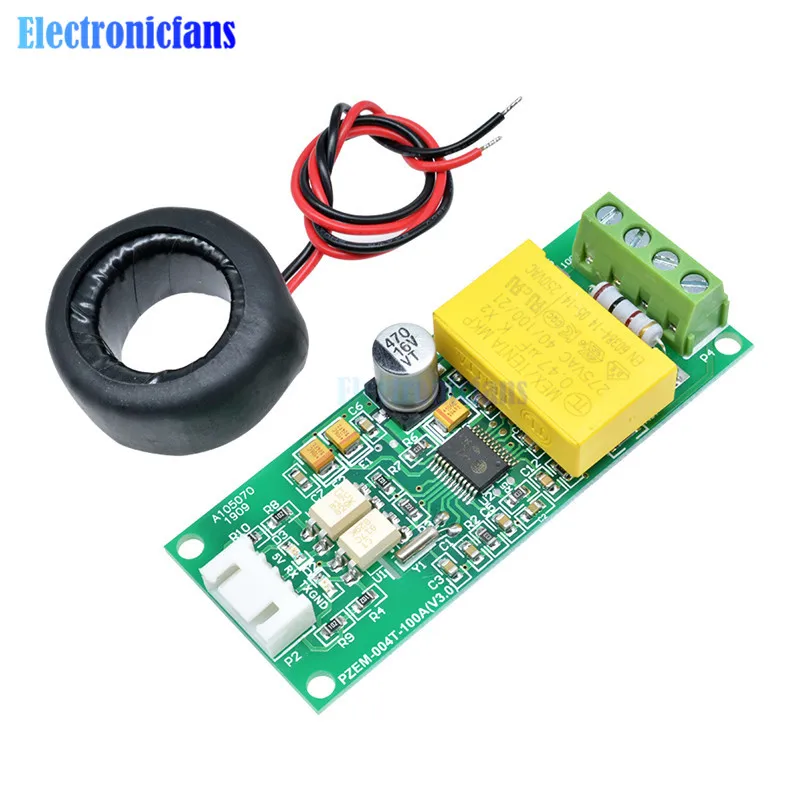
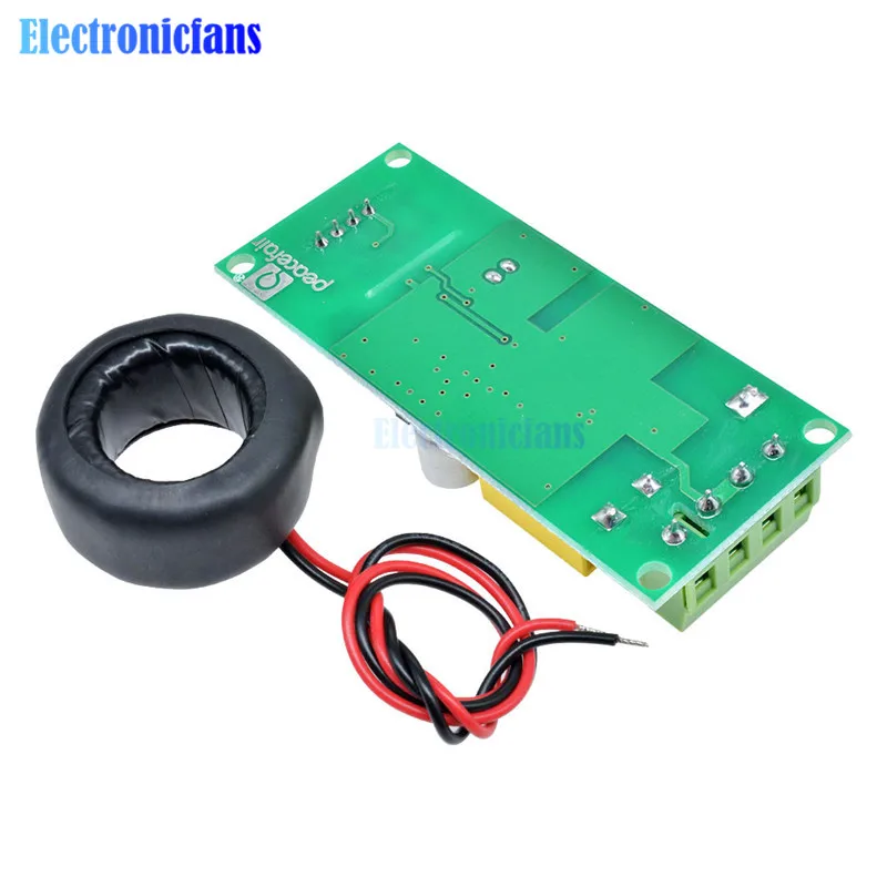
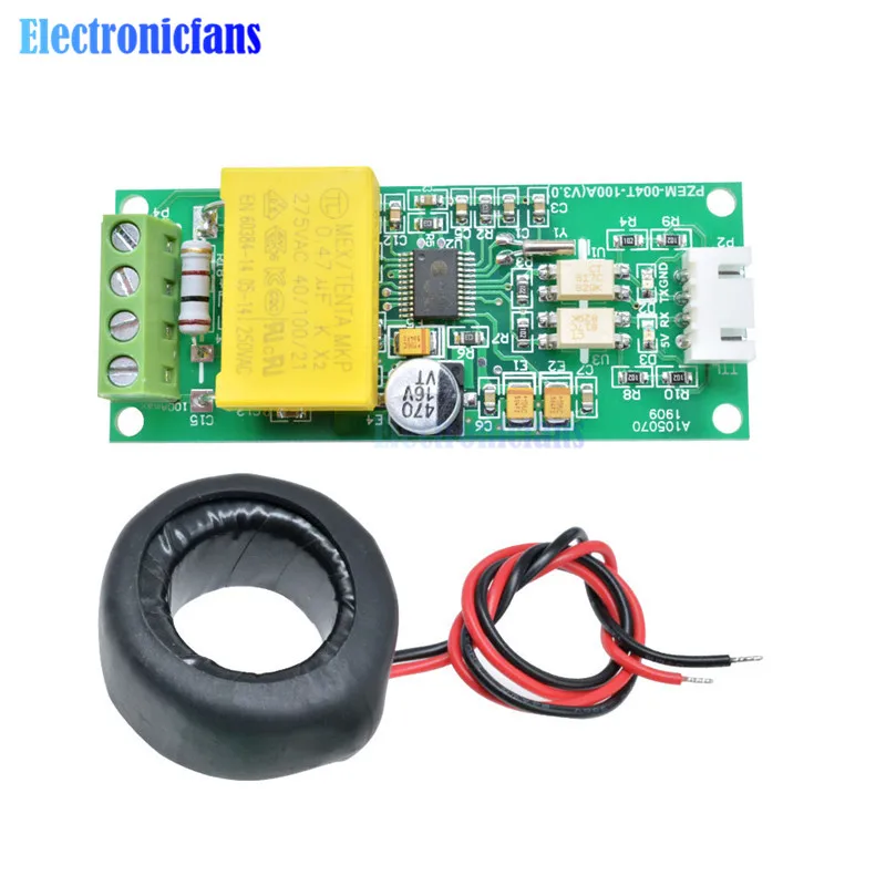
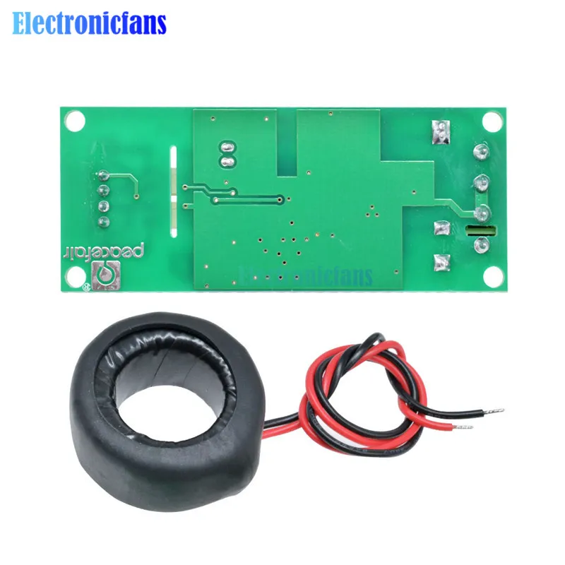
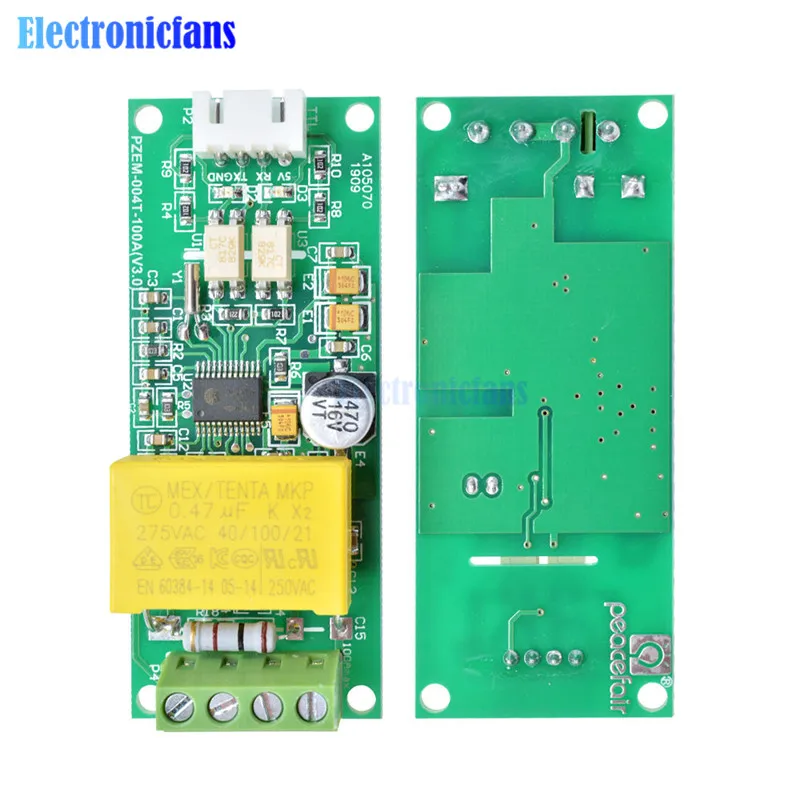
Model: PZEM-004T
Overview
This document describes the specification of the PZEM-004T AC communication module,
the module is mainly used for measuring AC voltage, current, active power, frequency, power
factor and active energy, the module is without display function, the data is read through the TTL
interface.
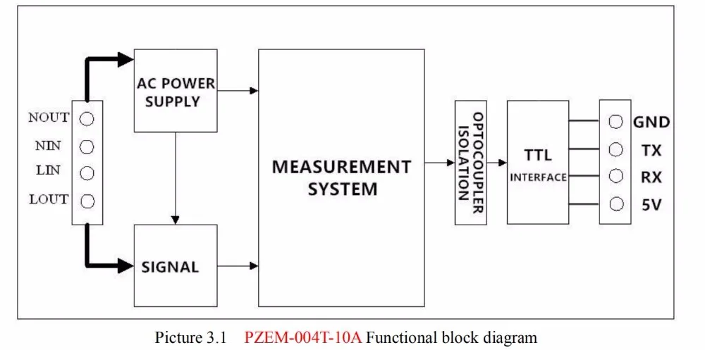
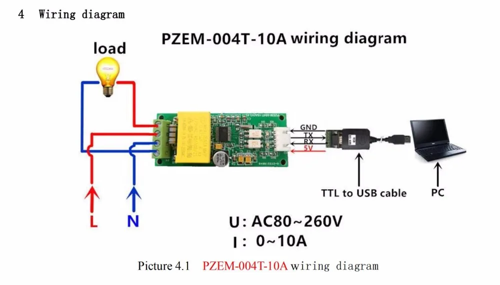
PZEM-004T-10A: Measuring Range 10A (Built-in Shunt)
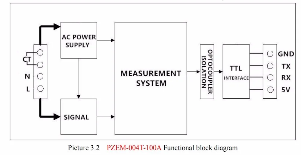
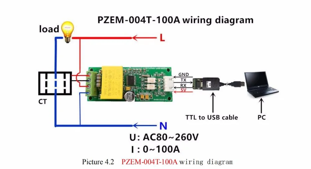
PZEM-004T-100A: Measuring Range 100A (external transformer)
1.Function description
1.1 Voltage
1.1.1 Measuring range:80~260V
1.1.2 Resolution: 0.1V
1.1.3 Measurement accuracy: 0.5%
1.2 Current
1.2.1 Measuring range: 0~10A(PZEM-004T-10A); 0~100A(PZEM-004T-100A)
1.2.2 Starting measure current: 0.01A(PZEM-004T-10A); 0.02A(PZEM-004T-100A)
1.2.3 Resolution: 0.001A
1.2.4 Measurement accuracy: 0.5%
1.3 Active power
1.3.1 Measuring range: 0~2.3kW(PZEM-004T-10A); 0~23kW(PZEM-004T-100A)
1.3.2 Starting measure power: 0.4W
1.3.3 Resolution: 0.1W
1.3.4 Display format:
<1000W, it display one decimal, such as: 999.9W
ge1000W, it display only integer, such as: 1000W
1.3.5 Measurement accuracy: 0.5%
1.4 Power factor
1.4.1 Measuring range: 0.00~1.00
1.4.2 Resolution: 0.01
1.4.3 Measurement accuracy: 1%
1.5 Frequency
1.5.1 Measuring range: 45Hz~65Hz
1.5.2 Resolution: 0.1Hz
1.5.3 Measurement accuracy: 0.5%
1.6 Active energy
1.6.1 Measuring range: 0~9999.99kWh
1.6.2 Resolution: 1Wh
1.6.3 Measurement accuracy: 0.5%
1.6.4 Display format:
<10kWh, the display unit is Wh(1kWh=1000Wh), such as: 9999Wh
ge10kWh, the display unit is kWh, such as: 9999.99kWh
1.6.5 Reset energy: use software to reset.
1.7 Over power alarm
Active power threshold can be set, when the measured active power exceeds the threshold, it
can alarm
1.8 Communication interface
RS485 interface。
2 Communication protocol
2.1 Physical layer protocol
Physical layer use UART to RS485 communication interface
Baud rate is 9600, 8 data bits, 1 stop bit, no parity
2.2 Application layer protocol
The application layer use the Modbus-RTU protocol to communicate. At present, it only
supports function codes such as 0x03 (Read Holding Register), 0x04 (Read Input Register), 0x06
(Write Single Register), 0x41 (Calibration), 0x42 (Reset energy).etc.
0x41 function code is only for internal use (address can be only 0xF8), used for factory
calibration and return to factory maintenance occasions, after the function code to increase 16-bit
password, the default password is 0x3721
The address range of the slave is 0x01 ~ 0xF7. The address 0x00 is used as the broadcast
address, the slave does not need to reply the master. The address 0xF8 is used as the general
address, this address can be only used in single-slave environment and can be used for calibration
etc.operation.
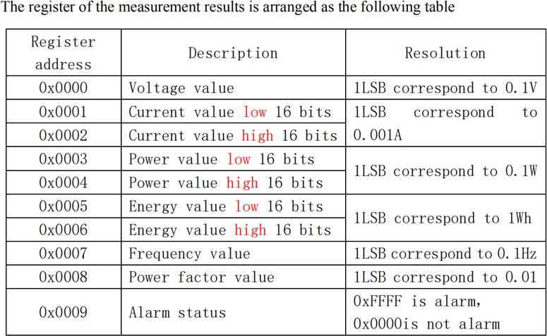
2.3 Read the measurement result
The command format of the master reads the measurement result is(total of 8 bytes):
Slave Address + 0x04 + Register Address High Byte + Register Address Low Byte + Number
of Registers High Byte + Number of Registers Low Byte + CRC Check High Byte + CRC Check
Low Byte.
The command format of the reply from the slave is divided into two kinds:
Correct Reply: Slave Address + 0x04 + Number of Bytes + Register 1 Data High Byte +
Register 1 Data Low Byte + ... + CRC Check High Byte + CRC Check Low Byte
Error Reply: Slave address + 0x84 + Abnormal code + CRC check high byte + CRC check
low byte
Abnormal code analyzed as following (the same below)
⚫ 0x01,Illegal function
⚫ 0x02,Illegal address
⚫ 0x03,Illegal data
⚫ 0x04,Slave error
For example, the master sends the following command (CRC check code is replaced by
0xHH and 0xLL, the same below)
0x01 + 0x04 + 0x00 + 0x00 + 0x00 + 0x0A + 0xHH + 0xLL
Indicates that the master needs to read 10 registers with slave address 0x01 and the start
address of the register is 0x0000
The correct reply from the slave is as following:
0x01 + 0x04 + 0x14 + 0x08 + 0x98 + 0x03 + 0xE8+0x00 + 0x00 +0x08 + 0x98+ 0x00 +
0x00 + 0x00 + 0x00 + 0x00 + 0x00 + 0x01 + 0xF4 + 0x00 + 0x64 + 0x00 + 0x00 + 0xHH + 0xLL
The above data shows
⚫ Voltage is 0x0898, converted to decimal is 2200, display 220.0V
⚫ Current is 0x000003E8, converted to decimal is 1000, display 1.000A
⚫ Power is 0x00000898, converted to decimal is 2200, display 220.0W
⚫ Energy is 0x00000000, converted to decimal is 0, display 0Wh
⚫ Frequency is 0x01F4, converted to decimal is 500, display 50.0Hz
⚫ Power factor is 0x0064, converted to decimal is 100, display 1.00
⚫ Alarm status is 0x0000, indicates that the current power is lower than the alarm power
threshold
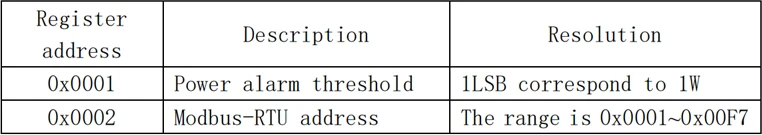
2.4 Read and modify the slave parameters
At present,it only supports reading and modifying slave address and power alarm threshold
The register is arranged as the following table
The command format of the master to read the slave parameters and read the measurement
results are same(descrybed in details in Section 2.3), only need to change the function code from
0x04 to 0x03.
The command format of the master to modify the slave parameters is (total of 8 bytes):
Slave Address + 0x06 + Register Address High Byte + Register Address Low Byte + Register
Value High Byte + Register Value Low Byte + CRC Check High Byte + CRC Check Low Byte.
The command format of the reply from the slave is divided into two kinds:
Correct Response: Slave Address + 0x06 + Number of Bytes + Register Address Low Byte +
Register Value High Byte + Register Value Low Byte + CRC Check High Byte + CRC Check Low
Byte.
Error Reply: Slave address + 0x86 + Abnormal code + CRC check high byte + CRC check
low byte.
For example, the master sets the slave's power alarm threshold:
0x01 + 0x06 + 0x00 + 0x01 + 0x08 + 0xFC + 0xHH + 0xLL
Indicates that the master needs to set the 0x0001 register (power alarm threshold) to 0x08FC
(2300W).
Set up correctly, the slave return to the data which is sent from the master.
For example, the master sets the address of the slave
0x01 + 0x06 + 0x00 + 0x02 + 0x00 + 0x05 + 0xHH + 0xLL
Indicates that the master needs to set the 0x0002 register (Modbus-RTU address) to 0x0005
Set up correctly, the slave return to the data which is sent from the master.
2.5 Reset energy
The command format of the master to reset the slave's energy is (total 4 bytes):
Slave address + 0x42 + CRC check high byte + CRC check low byte.
Correct reply: slave address + 0x42 + CRC check high byte + CRC check low byte.
Error Reply: Slave address + 0xC2 + Abnormal code + CRC check high byte + CRC check
low byte
2.6 Calibration
The command format of the master to calibrate the slave is (total 6 bytes):
0xF8 + 0x41 + 0x37 + 0x21 + CRC check high byte + CRC check low byte.
Correct reply: 0xF8 + 0x41 + 0x37 + 0x21 + CRC check high byte + CRC check low byte.
Error Reply: 0xF8 + 0xC1 + Abnormal code + CRC check high byte + CRC check low byte.
It should be noted that the calibration takes 3 to 4 seconds, after the master sends the
command, if the calibration is successful, it will take 3 ~ 4 seconds to receive the response from
the slave.
2.7 CRC check
CRC check use 16bits format, occupy two bytes, the generator polynomial is X16 + X15 +
X2 +1, the polynomial value used for calculation is 0xA001.
The value of the CRC check is a frame data divide all results of checking all the bytes except
the CRC check value.
3 Functional block diagram
5 Other instructi5.1The TTL interface ohich means, when come it cannot communica5.2 Working temper-20rsquoC ~ +60rsquoC。
Package include:
1x Digital Multi-function Meter
1x Coil

Purchasing & Delivery
Before you make your purchase, it’s helpful to know the measurements of the area you plan to place the furniture. You should also measure any doorways and hallways through which the furniture will pass to get to its final destination.Picking up at the store
Shopify Shop requires that all products are properly inspected BEFORE you take it home to insure there are no surprises. Our team is happy to open all packages and will assist in the inspection process. We will then reseal packages for safe transport. We encourage all customers to bring furniture pads or blankets to protect the items during transport as well as rope or tie downs. Shopify Shop will not be responsible for damage that occurs after leaving the store or during transit. It is the purchaser’s responsibility to make sure the correct items are picked up and in good condition.Delivery
Customers are able to pick the next available delivery day that best fits their schedule. However, to route stops as efficiently as possible, Shopify Shop will provide the time frame. Customers will not be able to choose a time. You will be notified in advance of your scheduled time frame. Please make sure that a responsible adult (18 years or older) will be home at that time.In preparation for your delivery, please remove existing furniture, pictures, mirrors, accessories, etc. to prevent damages. Also insure that the area where you would like your furniture placed is clear of any old furniture and any other items that may obstruct the passageway of the delivery team. Shopify Shop will deliver, assemble, and set-up your new furniture purchase and remove all packing materials from your home. Our delivery crews are not permitted to move your existing furniture or other household items. Delivery personnel will attempt to deliver the purchased items in a safe and controlled manner but will not attempt to place furniture if they feel it will result in damage to the product or your home. Delivery personnel are unable to remove doors, hoist furniture or carry furniture up more than 3 flights of stairs. An elevator must be available for deliveries to the 4th floor and above.
Other Customers also buy:
-
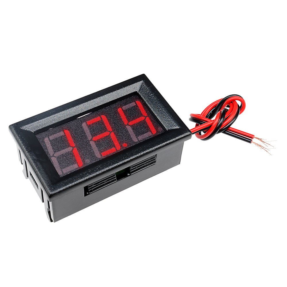
 Translation missing: en.products.product.regular_price $5.99{"id":4417209073735,"title":"AC Digital Multifunction Meter Watt Power Volt Amp TTL Current Test Module PZEM 004T With Coil 0 100A 80 260V AC For Arduino","handle":"ac-digital-multifunction-meter-watt-power-volt-amp-ttl-current-test-module-pzem-004t-with-coil-0-100a-80-260v-ac-for-arduino","description":"\u003cdiv\u003e\n\u003cwidget data-widget-type=\"customText\" id=\"23614578\" title=\"011086\" type=\"custom\"\u003e\u003c\/widget\u003e \u003cp\u003e \u003c\/p\u003e \u003cp\u003e \u003c\/p\u003e \u003cp\u003e \u003cimg alt=\"HTB1ZYSui4PI8KJjSspoq6x6MFXaU\" height=\"40\" src=\"https:\/\/ae01.alicdn.com\/kf\/HTB1ZYSui4PI8KJjSspoq6x6MFXaU.jpg\" width=\"950\"\u003e \u003c\/p\u003e \u003cp\u003e \u003c\/p\u003e \u003cdiv\u003e \u003cspan style=\"font-size: 18.0px;\"\u003e\u003cspan style=\"font-family: arial , helvetica , sans-serif;\"\u003e\u003cstrong\u003eModel: PZEM-004T\u003c\/strong\u003e\u003c\/span\u003e\u003c\/span\u003e \u003c\/div\u003e \u003cdiv\u003e \u003c\/div\u003e \u003cdiv\u003e \u003cdiv\u003e \u003cspan style=\"font-size: 18.0px;\"\u003e\u003cspan style=\"font-family: arial , helvetica , sans-serif;\"\u003eOverview\u003c\/span\u003e\u003c\/span\u003e \u003c\/div\u003e \u003cdiv\u003e \u003cspan style=\"font-size: 18.0px;\"\u003e\u003cspan style=\"font-family: arial , helvetica , sans-serif;\"\u003eThis document describes the specification of the PZEM-004T AC communication module,\u003c\/span\u003e\u003c\/span\u003e \u003c\/div\u003e \u003cdiv\u003e \u003cspan style=\"font-size: 18.0px;\"\u003e\u003cspan style=\"font-family: arial , helvetica , sans-serif;\"\u003ethe module is mainly used for measuring AC voltage, current, active power, frequency, power\u003c\/span\u003e\u003c\/span\u003e \u003c\/div\u003e \u003cdiv\u003e \u003cspan style=\"font-size: 18.0px;\"\u003e\u003cspan style=\"font-family: arial , helvetica , sans-serif;\"\u003efactor and active energy, the module is without display function, the data is read through the TTL\u003c\/span\u003e\u003c\/span\u003e \u003c\/div\u003e \u003cdiv\u003e \u003cspan style=\"font-size: 18.0px;\"\u003e\u003cspan style=\"font-family: arial , helvetica , sans-serif;\"\u003einterface.\u003c\/span\u003e\u003c\/span\u003e \u003c\/div\u003e \u003cdiv\u003e \u003cspan style=\"font-size: 18.0px;\"\u003e\u003cspan style=\"font-family: arial , helvetica , sans-serif;\"\u003ePZEM-004T-10A: Measuring Range 10A (Built-in Shunt)\u003c\/span\u003e\u003c\/span\u003e \u003c\/div\u003e \u003cdiv\u003e \u003cspan style=\"font-size: 18.0px;\"\u003e\u003cspan style=\"font-family: arial , helvetica , sans-serif;\"\u003ePZEM-004T-100A: Measuring Range 100A (external transformer)\u003c\/span\u003e\u003c\/span\u003e \u003c\/div\u003e \u003cdiv\u003e \u003cspan style=\"font-size: 18.0px;\"\u003e\u003cspan style=\"font-family: arial , helvetica , sans-serif;\"\u003e1.Function description\u003c\/span\u003e\u003c\/span\u003e \u003c\/div\u003e \u003cdiv\u003e \u003cspan style=\"font-size: 18.0px;\"\u003e\u003cspan style=\"font-family: arial , helvetica , sans-serif;\"\u003e1.1 Voltage\u003c\/span\u003e\u003c\/span\u003e \u003c\/div\u003e \u003cdiv\u003e \u003cspan style=\"font-size: 18.0px;\"\u003e\u003cspan style=\"font-family: arial , helvetica , sans-serif;\"\u003e1.1.1 Measuring range:80~260V\u003c\/span\u003e\u003c\/span\u003e \u003c\/div\u003e \u003cdiv\u003e \u003cspan style=\"font-size: 18.0px;\"\u003e\u003cspan style=\"font-family: arial , helvetica , sans-serif;\"\u003e1.1.2 Resolution: 0.1V\u003c\/span\u003e\u003c\/span\u003e \u003c\/div\u003e \u003cdiv\u003e \u003cspan style=\"font-size: 18.0px;\"\u003e\u003cspan style=\"font-family: arial , helvetica , sans-serif;\"\u003e1.1.3 Measurement accuracy: 0.5%\u003c\/span\u003e\u003c\/span\u003e \u003c\/div\u003e \u003cdiv\u003e \u003cspan style=\"font-size: 18.0px;\"\u003e\u003cspan style=\"font-family: arial , helvetica , sans-serif;\"\u003e1.2 Current\u003c\/span\u003e\u003c\/span\u003e \u003c\/div\u003e \u003cdiv\u003e \u003cspan style=\"font-size: 18.0px;\"\u003e\u003cspan style=\"font-family: arial , helvetica , sans-serif;\"\u003e1.2.1 Measuring range: 0~10A(PZEM-004T-10A); 0~100A(PZEM-004T-100A)\u003c\/span\u003e\u003c\/span\u003e \u003c\/div\u003e \u003cdiv\u003e \u003cspan style=\"font-size: 18.0px;\"\u003e\u003cspan style=\"font-family: arial , helvetica , sans-serif;\"\u003e1.2.2 Starting measure current: 0.01A(PZEM-004T-10A); 0.02A(PZEM-004T-100A)\u003c\/span\u003e\u003c\/span\u003e \u003c\/div\u003e \u003cdiv\u003e \u003cspan style=\"font-size: 18.0px;\"\u003e\u003cspan style=\"font-family: arial , helvetica , sans-serif;\"\u003e1.2.3 Resolution: 0.001A\u003c\/span\u003e\u003c\/span\u003e \u003c\/div\u003e \u003cdiv\u003e \u003cspan style=\"font-size: 18.0px;\"\u003e\u003cspan style=\"font-family: arial , helvetica , sans-serif;\"\u003e1.2.4 Measurement accuracy: 0.5%\u003c\/span\u003e\u003c\/span\u003e \u003c\/div\u003e \u003cdiv\u003e \u003cspan style=\"font-size: 18.0px;\"\u003e\u003cspan style=\"font-family: arial , helvetica , sans-serif;\"\u003e1.3 Active power\u003c\/span\u003e\u003c\/span\u003e \u003c\/div\u003e \u003cdiv\u003e \u003cspan style=\"font-size: 18.0px;\"\u003e\u003cspan style=\"font-family: arial , helvetica , sans-serif;\"\u003e1.3.1 Measuring range: 0~2.3kW(PZEM-004T-10A); 0~23kW(PZEM-004T-100A)\u003c\/span\u003e\u003c\/span\u003e \u003c\/div\u003e \u003cdiv\u003e \u003cspan style=\"font-size: 18.0px;\"\u003e\u003cspan style=\"font-family: arial , helvetica , sans-serif;\"\u003e1.3.2 Starting measure power: 0.4W\u003c\/span\u003e\u003c\/span\u003e \u003c\/div\u003e \u003cdiv\u003e \u003cspan style=\"font-size: 18.0px;\"\u003e\u003cspan style=\"font-family: arial , helvetica , sans-serif;\"\u003e1.3.3 Resolution: 0.1W\u003c\/span\u003e\u003c\/span\u003e \u003c\/div\u003e \u003cdiv\u003e \u003cspan style=\"font-size: 18.0px;\"\u003e\u003cspan style=\"font-family: arial , helvetica , sans-serif;\"\u003e1.3.4 Display format:\u003c\/span\u003e\u003c\/span\u003e \u003c\/div\u003e \u003cdiv\u003e \u003cspan style=\"font-size: 18.0px;\"\u003e\u003cspan style=\"font-family: arial , helvetica , sans-serif;\"\u003e<1000W, it display one decimal, such as: 999.9W\u003c\/span\u003e\u003c\/span\u003e \u003c\/div\u003e \u003cdiv\u003e \u003cspan style=\"font-size: 18.0px;\"\u003e\u003cspan style=\"font-family: arial , helvetica , sans-serif;\"\u003ege1000W, it display only integer, such as: 1000W\u003c\/span\u003e\u003c\/span\u003e \u003c\/div\u003e \u003cdiv\u003e \u003cspan style=\"font-size: 18.0px;\"\u003e\u003cspan style=\"font-family: arial , helvetica , sans-serif;\"\u003e1.3.5 Measurement accuracy: 0.5%\u003c\/span\u003e\u003c\/span\u003e \u003c\/div\u003e \u003cdiv\u003e \u003cspan style=\"font-size: 18.0px;\"\u003e\u003cspan style=\"font-family: arial , helvetica , sans-serif;\"\u003e1.4 Power factor\u003c\/span\u003e\u003c\/span\u003e \u003c\/div\u003e \u003cdiv\u003e \u003cspan style=\"font-size: 18.0px;\"\u003e\u003cspan style=\"font-family: arial , helvetica , sans-serif;\"\u003e1.4.1 Measuring range: 0.00~1.00\u003c\/span\u003e\u003c\/span\u003e \u003c\/div\u003e \u003cdiv\u003e \u003cspan style=\"font-size: 18.0px;\"\u003e\u003cspan style=\"font-family: arial , helvetica , sans-serif;\"\u003e1.4.2 Resolution: 0.01\u003c\/span\u003e\u003c\/span\u003e \u003c\/div\u003e \u003cdiv\u003e \u003cspan style=\"font-size: 18.0px;\"\u003e\u003cspan style=\"font-family: arial , helvetica , sans-serif;\"\u003e1.4.3 Measurement accuracy: 1%\u003c\/span\u003e\u003c\/span\u003e \u003c\/div\u003e \u003cdiv\u003e \u003cspan style=\"font-size: 18.0px;\"\u003e\u003cspan style=\"font-family: arial , helvetica , sans-serif;\"\u003e1.5 Frequency\u003c\/span\u003e\u003c\/span\u003e \u003c\/div\u003e \u003cdiv\u003e \u003cspan style=\"font-size: 18.0px;\"\u003e\u003cspan style=\"font-family: arial , helvetica , sans-serif;\"\u003e1.5.1 Measuring range: 45Hz~65Hz\u003c\/span\u003e\u003c\/span\u003e \u003c\/div\u003e \u003cdiv\u003e \u003cspan style=\"font-size: 18.0px;\"\u003e\u003cspan style=\"font-family: arial , helvetica , sans-serif;\"\u003e1.5.2 Resolution: 0.1Hz\u003c\/span\u003e\u003c\/span\u003e \u003c\/div\u003e \u003cdiv\u003e \u003cspan style=\"font-size: 18.0px;\"\u003e\u003cspan style=\"font-family: arial , helvetica , sans-serif;\"\u003e1.5.3 Measurement accuracy: 0.5%\u003c\/span\u003e\u003c\/span\u003e \u003c\/div\u003e \u003cdiv\u003e \u003cspan style=\"font-size: 18.0px;\"\u003e\u003cspan style=\"font-family: arial , helvetica , sans-serif;\"\u003e1.6 Active energy\u003c\/span\u003e\u003c\/span\u003e \u003c\/div\u003e \u003cdiv\u003e \u003cspan style=\"font-size: 18.0px;\"\u003e\u003cspan style=\"font-family: arial , helvetica , sans-serif;\"\u003e1.6.1 Measuring range: 0~9999.99kWh\u003c\/span\u003e\u003c\/span\u003e \u003c\/div\u003e \u003cdiv\u003e \u003cspan style=\"font-size: 18.0px;\"\u003e\u003cspan style=\"font-family: arial , helvetica , sans-serif;\"\u003e1.6.2 Resolution: 1Wh\u003c\/span\u003e\u003c\/span\u003e \u003c\/div\u003e \u003cdiv\u003e \u003cspan style=\"font-size: 18.0px;\"\u003e\u003cspan style=\"font-family: arial , helvetica , sans-serif;\"\u003e1.6.3 Measurement accuracy: 0.5%\u003c\/span\u003e\u003c\/span\u003e \u003c\/div\u003e \u003cdiv\u003e \u003cspan style=\"font-size: 18.0px;\"\u003e\u003cspan style=\"font-family: arial , helvetica , sans-serif;\"\u003e1.6.4 Display format:\u003c\/span\u003e\u003c\/span\u003e \u003c\/div\u003e \u003cdiv\u003e \u003cspan style=\"font-size: 18.0px;\"\u003e\u003cspan style=\"font-family: arial , helvetica , sans-serif;\"\u003e<10kWh, the display unit is Wh(1kWh=1000Wh), such as: 9999Wh\u003c\/span\u003e\u003c\/span\u003e \u003c\/div\u003e \u003cdiv\u003e \u003cspan style=\"font-size: 18.0px;\"\u003e\u003cspan style=\"font-family: arial , helvetica , sans-serif;\"\u003ege10kWh, the display unit is kWh, such as: 9999.99kWh\u003c\/span\u003e\u003c\/span\u003e \u003c\/div\u003e \u003cdiv\u003e \u003cspan style=\"font-size: 18.0px;\"\u003e\u003cspan style=\"font-family: arial , helvetica , sans-serif;\"\u003e1.6.5 Reset energy: use software to reset.\u003c\/span\u003e\u003c\/span\u003e \u003c\/div\u003e \u003cdiv\u003e \u003cspan style=\"font-size: 18.0px;\"\u003e\u003cspan style=\"font-family: arial , helvetica , sans-serif;\"\u003e1.7 Over power alarm\u003c\/span\u003e\u003c\/span\u003e \u003c\/div\u003e \u003cdiv\u003e \u003cspan style=\"font-size: 18.0px;\"\u003e\u003cspan style=\"font-family: arial , helvetica , sans-serif;\"\u003eActive power threshold can be set, when the measured active power exceeds the threshold, it\u003c\/span\u003e\u003c\/span\u003e \u003c\/div\u003e \u003cdiv\u003e \u003cspan style=\"font-size: 18.0px;\"\u003e\u003cspan style=\"font-family: arial , helvetica , sans-serif;\"\u003ecan alarm\u003c\/span\u003e\u003c\/span\u003e \u003c\/div\u003e \u003cdiv\u003e \u003cspan style=\"font-size: 18.0px;\"\u003e\u003cspan style=\"font-family: arial , helvetica , sans-serif;\"\u003e1.8 Communication interface\u003c\/span\u003e\u003c\/span\u003e \u003c\/div\u003e \u003cdiv\u003e \u003cspan style=\"font-size: 18.0px;\"\u003e\u003cspan style=\"font-family: arial , helvetica , sans-serif;\"\u003eRS485 interface。\u003c\/span\u003e\u003c\/span\u003e \u003c\/div\u003e \u003cdiv\u003e \u003cspan style=\"font-size: 18.0px;\"\u003e\u003cspan style=\"font-family: arial , helvetica , sans-serif;\"\u003e2 Communication protocol\u003c\/span\u003e\u003c\/span\u003e \u003c\/div\u003e \u003cdiv\u003e \u003cspan style=\"font-size: 18.0px;\"\u003e\u003cspan style=\"font-family: arial , helvetica , sans-serif;\"\u003e2.1 Physical layer protocol\u003c\/span\u003e\u003c\/span\u003e \u003c\/div\u003e \u003cdiv\u003e \u003cspan style=\"font-size: 18.0px;\"\u003e\u003cspan style=\"font-family: arial , helvetica , sans-serif;\"\u003ePhysical layer use UART to RS485 communication interface\u003c\/span\u003e\u003c\/span\u003e \u003c\/div\u003e \u003cdiv\u003e \u003cspan style=\"font-size: 18.0px;\"\u003e\u003cspan style=\"font-family: arial , helvetica , sans-serif;\"\u003eBaud rate is 9600, 8 data bits, 1 stop bit, no parity\u003c\/span\u003e\u003c\/span\u003e \u003c\/div\u003e \u003cdiv\u003e \u003cspan style=\"font-size: 18.0px;\"\u003e\u003cspan style=\"font-family: arial , helvetica , sans-serif;\"\u003e2.2 Application layer protocol\u003c\/span\u003e\u003c\/span\u003e \u003c\/div\u003e \u003cdiv\u003e \u003cspan style=\"font-size: 18.0px;\"\u003e\u003cspan style=\"font-family: arial , helvetica , sans-serif;\"\u003eThe application layer use the Modbus-RTU protocol to communicate. At present, it only\u003c\/span\u003e\u003c\/span\u003e \u003c\/div\u003e \u003cdiv\u003e \u003cspan style=\"font-size: 18.0px;\"\u003e\u003cspan style=\"font-family: arial , helvetica , sans-serif;\"\u003esupports function codes such as 0x03 (Read Holding Register), 0x04 (Read Input Register), 0x06\u003c\/span\u003e\u003c\/span\u003e \u003c\/div\u003e \u003cdiv\u003e \u003cspan style=\"font-size: 18.0px;\"\u003e\u003cspan style=\"font-family: arial , helvetica , sans-serif;\"\u003e(Write Single Register), 0x41 (Calibration), 0x42 (Reset energy).etc.\u003c\/span\u003e\u003c\/span\u003e \u003c\/div\u003e \u003cdiv\u003e \u003cspan style=\"font-size: 18.0px;\"\u003e\u003cspan style=\"font-family: arial , helvetica , sans-serif;\"\u003e0x41 function code is only for internal use (address can be only 0xF8), used for factory\u003c\/span\u003e\u003c\/span\u003e \u003c\/div\u003e \u003cdiv\u003e \u003cspan style=\"font-size: 18.0px;\"\u003e\u003cspan style=\"font-family: arial , helvetica , sans-serif;\"\u003ecalibration and return to factory maintenance occasions, after the function code to increase 16-bit\u003c\/span\u003e\u003c\/span\u003e \u003c\/div\u003e \u003cdiv\u003e \u003cspan style=\"font-size: 18.0px;\"\u003e\u003cspan style=\"font-family: arial , helvetica , sans-serif;\"\u003epassword, the default password is 0x3721\u003c\/span\u003e\u003c\/span\u003e \u003c\/div\u003e \u003cdiv\u003e \u003cspan style=\"font-size: 18.0px;\"\u003e\u003cspan style=\"font-family: arial , helvetica , sans-serif;\"\u003eThe address range of the slave is 0x01 ~ 0xF7. The address 0x00 is used as the broadcast\u003c\/span\u003e\u003c\/span\u003e \u003c\/div\u003e \u003cdiv\u003e \u003cspan style=\"font-size: 18.0px;\"\u003e\u003cspan style=\"font-family: arial , helvetica , sans-serif;\"\u003eaddress, the slave does not need to reply the master. The address 0xF8 is used as the general\u003c\/span\u003e\u003c\/span\u003e \u003c\/div\u003e \u003cdiv\u003e \u003cspan style=\"font-size: 18.0px;\"\u003e\u003cspan style=\"font-family: arial , helvetica , sans-serif;\"\u003eaddress, this address can be only used in single-slave environment and can be used for calibration\u003c\/span\u003e\u003c\/span\u003e \u003c\/div\u003e \u003cdiv\u003e \u003cspan style=\"font-size: 18.0px;\"\u003e\u003cspan style=\"font-family: arial , helvetica , sans-serif;\"\u003eetc.operation.\u003c\/span\u003e\u003c\/span\u003e \u003c\/div\u003e \u003cdiv\u003e \u003cspan style=\"font-size: 18.0px;\"\u003e\u003cspan style=\"font-family: arial , helvetica , sans-serif;\"\u003e2.3 Read the measurement result\u003c\/span\u003e\u003c\/span\u003e \u003c\/div\u003e \u003cdiv\u003e \u003cspan style=\"font-size: 18.0px;\"\u003e\u003cspan style=\"font-family: arial , helvetica , sans-serif;\"\u003eThe command format of the master reads the measurement result is(total of 8 bytes):\u003c\/span\u003e\u003c\/span\u003e \u003c\/div\u003e \u003cdiv\u003e \u003cspan style=\"font-size: 18.0px;\"\u003e\u003cspan style=\"font-family: arial , helvetica , sans-serif;\"\u003eSlave Address + 0x04 + Register Address High Byte + Register Address Low Byte + Number\u003c\/span\u003e\u003c\/span\u003e \u003c\/div\u003e \u003cdiv\u003e \u003cspan style=\"font-size: 18.0px;\"\u003e\u003cspan style=\"font-family: arial , helvetica , sans-serif;\"\u003eof Registers High Byte + Number of Registers Low Byte + CRC Check High Byte + CRC Check\u003c\/span\u003e\u003c\/span\u003e \u003c\/div\u003e \u003cdiv\u003e \u003cspan style=\"font-size: 18.0px;\"\u003e\u003cspan style=\"font-family: arial , helvetica , sans-serif;\"\u003eLow Byte.\u003c\/span\u003e\u003c\/span\u003e \u003c\/div\u003e \u003cdiv\u003e \u003cspan style=\"font-size: 18.0px;\"\u003e\u003cspan style=\"font-family: arial , helvetica , sans-serif;\"\u003eThe command format of the reply from the slave is divided into two kinds:\u003c\/span\u003e\u003c\/span\u003e \u003c\/div\u003e \u003cdiv\u003e \u003cspan style=\"font-size: 18.0px;\"\u003e\u003cspan style=\"font-family: arial , helvetica , sans-serif;\"\u003eCorrect Reply: Slave Address + 0x04 + Number of Bytes + Register 1 Data High Byte +\u003c\/span\u003e\u003c\/span\u003e \u003c\/div\u003e \u003cdiv\u003e \u003cspan style=\"font-size: 18.0px;\"\u003e\u003cspan style=\"font-family: arial , helvetica , sans-serif;\"\u003eRegister 1 Data Low Byte + ... + CRC Check High Byte + CRC Check Low Byte\u003c\/span\u003e\u003c\/span\u003e \u003c\/div\u003e \u003cdiv\u003e \u003cspan style=\"font-size: 18.0px;\"\u003e\u003cspan style=\"font-family: arial , helvetica , sans-serif;\"\u003eError Reply: Slave address + 0x84 + Abnormal code + CRC check high byte + CRC check\u003c\/span\u003e\u003c\/span\u003e \u003c\/div\u003e \u003cdiv\u003e \u003cspan style=\"font-size: 18.0px;\"\u003e\u003cspan style=\"font-family: arial , helvetica , sans-serif;\"\u003elow byte\u003c\/span\u003e\u003c\/span\u003e \u003c\/div\u003e \u003cdiv\u003e \u003cspan style=\"font-size: 18.0px;\"\u003e\u003cspan style=\"font-family: arial , helvetica , sans-serif;\"\u003eAbnormal code analyzed as following (the same below)\u003c\/span\u003e\u003c\/span\u003e \u003c\/div\u003e \u003cdiv\u003e \u003cspan style=\"font-size: 18.0px;\"\u003e\u003cspan style=\"font-family: arial , helvetica , sans-serif;\"\u003e⚫ 0x01,Illegal function\u003c\/span\u003e\u003c\/span\u003e \u003c\/div\u003e \u003cdiv\u003e \u003cspan style=\"font-size: 18.0px;\"\u003e\u003cspan style=\"font-family: arial , helvetica , sans-serif;\"\u003e⚫ 0x02,Illegal address\u003c\/span\u003e\u003c\/span\u003e \u003c\/div\u003e \u003cdiv\u003e \u003cspan style=\"font-size: 18.0px;\"\u003e\u003cspan style=\"font-family: arial , helvetica , sans-serif;\"\u003e⚫ 0x03,Illegal data\u003c\/span\u003e\u003c\/span\u003e \u003c\/div\u003e \u003c\/div\u003e \u003cdiv\u003e \u003cspan style=\"font-family: arial , helvetica , sans-serif;font-size: 18.0px;\"\u003e⚫ 0x04,Slave error\u003c\/span\u003e \u003cspan style=\"font-family: arial , helvetica , sans-serif;font-size: 18.0px;\"\u003e \u003c\/span\u003e \u003c\/div\u003e \u003cdiv\u003e \u003cspan style=\"font-family: arial , helvetica , sans-serif;font-size: 18.0px;\"\u003e\u003cimg alt=\"1\" src=\"https:\/\/ae01.alicdn.com\/kf\/HTB1hnE1RzTpK1RjSZKPq6y3UpXaT.jpg\"\u003e\u003c\/span\u003e \u003c\/div\u003e \u003cdiv\u003e \u003c\/div\u003e \u003cdiv\u003e \u003cspan style=\"font-family: arial , helvetica , sans-serif;font-size: 18.0px;\"\u003eFor example, the master sends the following command (CRC check code is replaced by\u003c\/span\u003e \u003c\/div\u003e \u003cdiv\u003e \u003cspan style=\"font-size: 18.0px;\"\u003e\u003cspan style=\"font-family: arial , helvetica , sans-serif;\"\u003e0xHH and 0xLL, the same below)\u003c\/span\u003e\u003c\/span\u003e \u003c\/div\u003e \u003cdiv\u003e \u003cspan style=\"font-size: 18.0px;\"\u003e\u003cspan style=\"font-family: arial , helvetica , sans-serif;\"\u003e0x01 + 0x04 + 0x00 + 0x00 + 0x00 + 0x0A + 0xHH + 0xLL\u003c\/span\u003e\u003c\/span\u003e \u003c\/div\u003e \u003cdiv\u003e \u003cspan style=\"font-size: 18.0px;\"\u003e\u003cspan style=\"font-family: arial , helvetica , sans-serif;\"\u003eIndicates that the master needs to read 10 registers with slave address 0x01 and the start\u003c\/span\u003e\u003c\/span\u003e \u003c\/div\u003e \u003cdiv\u003e \u003cspan style=\"font-size: 18.0px;\"\u003e\u003cspan style=\"font-family: arial , helvetica , sans-serif;\"\u003eaddress of the register is 0x0000\u003c\/span\u003e\u003c\/span\u003e \u003c\/div\u003e \u003cdiv\u003e \u003cspan style=\"font-size: 18.0px;\"\u003e\u003cspan style=\"font-family: arial , helvetica , sans-serif;\"\u003eThe correct reply from the slave is as following:\u003c\/span\u003e\u003c\/span\u003e \u003c\/div\u003e \u003cdiv\u003e \u003cspan style=\"font-size: 18.0px;\"\u003e\u003cspan style=\"font-family: arial , helvetica , sans-serif;\"\u003e0x01 + 0x04 + 0x14 + 0x08 + 0x98 + 0x03 + 0xE8+0x00 + 0x00 +0x08 + 0x98+ 0x00 +\u003c\/span\u003e\u003c\/span\u003e \u003c\/div\u003e \u003cdiv\u003e \u003cspan style=\"font-size: 18.0px;\"\u003e\u003cspan style=\"font-family: arial , helvetica , sans-serif;\"\u003e0x00 + 0x00 + 0x00 + 0x00 + 0x00 + 0x01 + 0xF4 + 0x00 + 0x64 + 0x00 + 0x00 + 0xHH + 0xLL\u003c\/span\u003e\u003c\/span\u003e \u003c\/div\u003e \u003cdiv\u003e \u003cspan style=\"font-size: 18.0px;\"\u003e\u003cspan style=\"font-family: arial , helvetica , sans-serif;\"\u003eThe above data shows\u003c\/span\u003e\u003c\/span\u003e \u003c\/div\u003e \u003cdiv\u003e \u003cspan style=\"font-size: 18.0px;\"\u003e\u003cspan style=\"font-family: arial , helvetica , sans-serif;\"\u003e⚫ Voltage is 0x0898, converted to decimal is 2200, display 220.0V\u003c\/span\u003e\u003c\/span\u003e \u003c\/div\u003e \u003cdiv\u003e \u003cspan style=\"font-size: 18.0px;\"\u003e\u003cspan style=\"font-family: arial , helvetica , sans-serif;\"\u003e⚫ Current is 0x000003E8, converted to decimal is 1000, display 1.000A\u003c\/span\u003e\u003c\/span\u003e \u003c\/div\u003e \u003cdiv\u003e \u003cspan style=\"font-size: 18.0px;\"\u003e\u003cspan style=\"font-family: arial , helvetica , sans-serif;\"\u003e⚫ Power is 0x00000898, converted to decimal is 2200, display 220.0W\u003c\/span\u003e\u003c\/span\u003e \u003c\/div\u003e \u003cdiv\u003e \u003cspan style=\"font-size: 18.0px;\"\u003e\u003cspan style=\"font-family: arial , helvetica , sans-serif;\"\u003e⚫ Energy is 0x00000000, converted to decimal is 0, display 0Wh\u003c\/span\u003e\u003c\/span\u003e \u003c\/div\u003e \u003cdiv\u003e \u003cspan style=\"font-size: 18.0px;\"\u003e\u003cspan style=\"font-family: arial , helvetica , sans-serif;\"\u003e⚫ Frequency is 0x01F4, converted to decimal is 500, display 50.0Hz\u003c\/span\u003e\u003c\/span\u003e \u003c\/div\u003e \u003cdiv\u003e \u003cspan style=\"font-size: 18.0px;\"\u003e\u003cspan style=\"font-family: arial , helvetica , sans-serif;\"\u003e⚫ Power factor is 0x0064, converted to decimal is 100, display 1.00\u003c\/span\u003e\u003c\/span\u003e \u003c\/div\u003e \u003cdiv\u003e \u003cspan style=\"font-size: 18.0px;\"\u003e\u003cspan style=\"font-family: arial , helvetica , sans-serif;\"\u003e⚫ Alarm status is 0x0000, indicates that the current power is lower than the alarm power\u003c\/span\u003e\u003c\/span\u003e \u003c\/div\u003e \u003cdiv\u003e \u003cspan style=\"font-size: 18.0px;\"\u003e\u003cspan style=\"font-family: arial , helvetica , sans-serif;\"\u003ethreshold\u003c\/span\u003e\u003c\/span\u003e \u003c\/div\u003e \u003cdiv\u003e \u003cspan style=\"font-size: 18.0px;\"\u003e\u003cspan style=\"font-family: arial , helvetica , sans-serif;\"\u003e2.4 Read and modify the slave parameters\u003c\/span\u003e\u003c\/span\u003e \u003c\/div\u003e \u003cdiv\u003e \u003cspan style=\"font-size: 18.0px;\"\u003e\u003cspan style=\"font-family: arial , helvetica , sans-serif;\"\u003eAt present,it only supports reading and modifying slave address and power alarm threshold\u003c\/span\u003e\u003c\/span\u003e \u003c\/div\u003e \u003cdiv\u003e \u003cspan style=\"font-size: 18.0px;\"\u003e\u003cspan style=\"font-family: arial , helvetica , sans-serif;\"\u003eThe register is arranged as the following table\u003c\/span\u003e\u003c\/span\u003e \u003c\/div\u003e \u003cdiv\u003e \u003cspan style=\"font-size: 18.0px;\"\u003e\u003cspan style=\"font-family: arial , helvetica , sans-serif;\"\u003e\u003cimg alt=\"2\" src=\"https:\/\/ae01.alicdn.com\/kf\/HTB1QmhWeK3tHKVjSZSgq6x4QFXa5.jpg\"\u003e\u003c\/span\u003e\u003c\/span\u003e \u003c\/div\u003e \u003cdiv\u003e \u003c\/div\u003e \u003cdiv\u003e \u003cspan style=\"font-family: arial , helvetica , sans-serif;font-size: 18.0px;\"\u003eThe command format of the master to read the slave parameters and read the measurement\u003c\/span\u003e \u003c\/div\u003e \u003cdiv\u003e \u003cspan style=\"font-size: 18.0px;\"\u003e\u003cspan style=\"font-family: arial , helvetica , sans-serif;\"\u003eresults are same(descrybed in details in Section 2.3), only need to change the function code from\u003c\/span\u003e\u003c\/span\u003e \u003c\/div\u003e \u003cdiv\u003e \u003cspan style=\"font-size: 18.0px;\"\u003e\u003cspan style=\"font-family: arial , helvetica , sans-serif;\"\u003e0x04 to 0x03.\u003c\/span\u003e\u003c\/span\u003e \u003c\/div\u003e \u003cdiv\u003e \u003cspan style=\"font-size: 18.0px;\"\u003e\u003cspan style=\"font-family: arial , helvetica , sans-serif;\"\u003eThe command format of the master to modify the slave parameters is (total of 8 bytes):\u003c\/span\u003e\u003c\/span\u003e \u003c\/div\u003e \u003cdiv\u003e \u003cspan style=\"font-size: 18.0px;\"\u003e\u003cspan style=\"font-family: arial , helvetica , sans-serif;\"\u003eSlave Address + 0x06 + Register Address High Byte + Register Address Low Byte + Register\u003c\/span\u003e\u003c\/span\u003e \u003c\/div\u003e \u003cdiv\u003e \u003cspan style=\"font-size: 18.0px;\"\u003e\u003cspan style=\"font-family: arial , helvetica , sans-serif;\"\u003eValue High Byte + Register Value Low Byte + CRC Check High Byte + CRC Check Low Byte.\u003c\/span\u003e\u003c\/span\u003e \u003c\/div\u003e \u003cdiv\u003e \u003cspan style=\"font-size: 18.0px;\"\u003e\u003cspan style=\"font-family: arial , helvetica , sans-serif;\"\u003eThe command format of the reply from the slave is divided into two kinds:\u003c\/span\u003e\u003c\/span\u003e \u003c\/div\u003e \u003cdiv\u003e \u003cspan style=\"font-size: 18.0px;\"\u003e\u003cspan style=\"font-family: arial , helvetica , sans-serif;\"\u003eCorrect Response: Slave Address + 0x06 + Number of Bytes + Register Address Low Byte +\u003c\/span\u003e\u003c\/span\u003e \u003c\/div\u003e \u003cdiv\u003e \u003cspan style=\"font-size: 18.0px;\"\u003e\u003cspan style=\"font-family: arial , helvetica , sans-serif;\"\u003eRegister Value High Byte + Register Value Low Byte + CRC Check High Byte + CRC Check Low\u003c\/span\u003e\u003c\/span\u003e \u003c\/div\u003e \u003cdiv\u003e \u003cspan style=\"font-size: 18.0px;\"\u003e\u003cspan style=\"font-family: arial , helvetica , sans-serif;\"\u003eByte.\u003c\/span\u003e\u003c\/span\u003e \u003c\/div\u003e \u003cdiv\u003e \u003cspan style=\"font-size: 18.0px;\"\u003e\u003cspan style=\"font-family: arial , helvetica , sans-serif;\"\u003eError Reply: Slave address + 0x86 + Abnormal code + CRC check high byte + CRC check\u003c\/span\u003e\u003c\/span\u003e \u003c\/div\u003e \u003cdiv\u003e \u003cspan style=\"font-size: 18.0px;\"\u003e\u003cspan style=\"font-family: arial , helvetica , sans-serif;\"\u003elow byte.\u003c\/span\u003e\u003c\/span\u003e \u003c\/div\u003e \u003cdiv\u003e \u003cspan style=\"font-size: 18.0px;\"\u003e\u003cspan style=\"font-family: arial , helvetica , sans-serif;\"\u003eFor example, the master sets the slave's power alarm threshold:\u003c\/span\u003e\u003c\/span\u003e \u003c\/div\u003e \u003cdiv\u003e \u003cspan style=\"font-size: 18.0px;\"\u003e\u003cspan style=\"font-family: arial , helvetica , sans-serif;\"\u003e0x01 + 0x06 + 0x00 + 0x01 + 0x08 + 0xFC + 0xHH + 0xLL\u003c\/span\u003e\u003c\/span\u003e \u003c\/div\u003e \u003cdiv\u003e \u003cspan style=\"font-size: 18.0px;\"\u003e\u003cspan style=\"font-family: arial , helvetica , sans-serif;\"\u003eIndicates that the master needs to set the 0x0001 register (power alarm threshold) to 0x08FC\u003c\/span\u003e\u003c\/span\u003e \u003c\/div\u003e \u003cdiv\u003e \u003cspan style=\"font-size: 18.0px;\"\u003e\u003cspan style=\"font-family: arial , helvetica , sans-serif;\"\u003e(2300W).\u003c\/span\u003e\u003c\/span\u003e \u003c\/div\u003e \u003cdiv\u003e \u003cspan style=\"font-size: 18.0px;\"\u003e\u003cspan style=\"font-family: arial , helvetica , sans-serif;\"\u003eSet up correctly, the slave return to the data which is sent from the master.\u003c\/span\u003e\u003c\/span\u003e \u003c\/div\u003e \u003cdiv\u003e \u003cspan style=\"font-size: 18.0px;\"\u003e\u003cspan style=\"font-family: arial , helvetica , sans-serif;\"\u003eFor example, the master sets the address of the slave\u003c\/span\u003e\u003c\/span\u003e \u003c\/div\u003e \u003cdiv\u003e \u003cspan style=\"font-size: 18.0px;\"\u003e\u003cspan style=\"font-family: arial , helvetica , sans-serif;\"\u003e0x01 + 0x06 + 0x00 + 0x02 + 0x00 + 0x05 + 0xHH + 0xLL\u003c\/span\u003e\u003c\/span\u003e \u003c\/div\u003e \u003cdiv\u003e \u003cspan style=\"font-size: 18.0px;\"\u003e\u003cspan style=\"font-family: arial , helvetica , sans-serif;\"\u003eIndicates that the master needs to set the 0x0002 register (Modbus-RTU address) to 0x0005\u003c\/span\u003e\u003c\/span\u003e \u003c\/div\u003e \u003cdiv\u003e \u003cspan style=\"font-size: 18.0px;\"\u003e\u003cspan style=\"font-family: arial , helvetica , sans-serif;\"\u003eSet up correctly, the slave return to the data which is sent from the master.\u003c\/span\u003e\u003c\/span\u003e \u003c\/div\u003e \u003cdiv\u003e \u003cspan style=\"font-size: 18.0px;\"\u003e\u003cspan style=\"font-family: arial , helvetica , sans-serif;\"\u003e2.5 Reset energy\u003c\/span\u003e\u003c\/span\u003e \u003c\/div\u003e \u003cdiv\u003e \u003cspan style=\"font-size: 18.0px;\"\u003e\u003cspan style=\"font-family: arial , helvetica , sans-serif;\"\u003eThe command format of the master to reset the slave's energy is (total 4 bytes):\u003c\/span\u003e\u003c\/span\u003e \u003c\/div\u003e \u003cdiv\u003e \u003cspan style=\"font-size: 18.0px;\"\u003e\u003cspan style=\"font-family: arial , helvetica , sans-serif;\"\u003eSlave address + 0x42 + CRC check high byte + CRC check low byte.\u003c\/span\u003e\u003c\/span\u003e \u003c\/div\u003e \u003cdiv\u003e \u003cspan style=\"font-size: 18.0px;\"\u003e\u003cspan style=\"font-family: arial , helvetica , sans-serif;\"\u003eCorrect reply: slave address + 0x42 + CRC check high byte + CRC check low byte.\u003c\/span\u003e\u003c\/span\u003e \u003c\/div\u003e \u003cdiv\u003e \u003cspan style=\"font-size: 18.0px;\"\u003e\u003cspan style=\"font-family: arial , helvetica , sans-serif;\"\u003eError Reply: Slave address + 0xC2 + Abnormal code + CRC check high byte + CRC check\u003c\/span\u003e\u003c\/span\u003e \u003c\/div\u003e \u003cdiv\u003e \u003cspan style=\"font-size: 18.0px;\"\u003e\u003cspan style=\"font-family: arial , helvetica , sans-serif;\"\u003elow byte\u003c\/span\u003e\u003c\/span\u003e \u003c\/div\u003e \u003cdiv\u003e \u003cspan style=\"font-size: 18.0px;\"\u003e\u003cspan style=\"font-family: arial , helvetica , sans-serif;\"\u003e2.6 Calibration\u003c\/span\u003e\u003c\/span\u003e \u003c\/div\u003e \u003cdiv\u003e \u003cspan style=\"font-size: 18.0px;\"\u003e\u003cspan style=\"font-family: arial , helvetica , sans-serif;\"\u003eThe command format of the master to calibrate the slave is (total 6 bytes):\u003c\/span\u003e\u003c\/span\u003e \u003c\/div\u003e \u003cdiv\u003e \u003cspan style=\"font-size: 18.0px;\"\u003e\u003cspan style=\"font-family: arial , helvetica , sans-serif;\"\u003e0xF8 + 0x41 + 0x37 + 0x21 + CRC check high byte + CRC check low byte.\u003c\/span\u003e\u003c\/span\u003e \u003c\/div\u003e \u003cdiv\u003e \u003cspan style=\"font-size: 18.0px;\"\u003e\u003cspan style=\"font-family: arial , helvetica , sans-serif;\"\u003eCorrect reply: 0xF8 + 0x41 + 0x37 + 0x21 + CRC check high byte + CRC check low byte.\u003c\/span\u003e\u003c\/span\u003e \u003c\/div\u003e \u003cdiv\u003e \u003cspan style=\"font-size: 18.0px;\"\u003e\u003cspan style=\"font-family: arial , helvetica , sans-serif;\"\u003eError Reply: 0xF8 + 0xC1 + Abnormal code + CRC check high byte + CRC check low byte.\u003c\/span\u003e\u003c\/span\u003e \u003c\/div\u003e \u003cdiv\u003e \u003cspan style=\"font-size: 18.0px;\"\u003e\u003cspan style=\"font-family: arial , helvetica , sans-serif;\"\u003eIt should be noted that the calibration takes 3 to 4 seconds, after the master sends the\u003c\/span\u003e\u003c\/span\u003e \u003c\/div\u003e \u003cdiv\u003e \u003cspan style=\"font-size: 18.0px;\"\u003e\u003cspan style=\"font-family: arial , helvetica , sans-serif;\"\u003ecommand, if the calibration is successful, it will take 3 ~ 4 seconds to receive the response from\u003c\/span\u003e\u003c\/span\u003e \u003c\/div\u003e \u003cdiv\u003e \u003cspan style=\"font-size: 18.0px;\"\u003e\u003cspan style=\"font-family: arial , helvetica , sans-serif;\"\u003ethe slave.\u003c\/span\u003e\u003c\/span\u003e \u003c\/div\u003e \u003cdiv\u003e \u003cspan style=\"font-size: 18.0px;\"\u003e\u003cspan style=\"font-family: arial , helvetica , sans-serif;\"\u003e2.7 CRC check\u003c\/span\u003e\u003c\/span\u003e \u003c\/div\u003e \u003cdiv\u003e \u003cspan style=\"font-size: 18.0px;\"\u003e\u003cspan style=\"font-family: arial , helvetica , sans-serif;\"\u003eCRC check use 16bits format, occupy two bytes, the generator polynomial is X16 + X15 +\u003c\/span\u003e\u003c\/span\u003e \u003c\/div\u003e \u003cdiv\u003e \u003cspan style=\"font-size: 18.0px;\"\u003e\u003cspan style=\"font-family: arial , helvetica , sans-serif;\"\u003eX2 +1, the polynomial value used for calculation is 0xA001.\u003c\/span\u003e\u003c\/span\u003e \u003c\/div\u003e \u003cdiv\u003e \u003cspan style=\"font-size: 18.0px;\"\u003e\u003cspan style=\"font-family: arial , helvetica , sans-serif;\"\u003eThe value of the CRC check is a frame data divide all results of checking all the bytes except\u003c\/span\u003e\u003c\/span\u003e \u003c\/div\u003e \u003cdiv\u003e \u003cspan style=\"font-size: 18.0px;\"\u003e\u003cspan style=\"font-family: arial , helvetica , sans-serif;\"\u003ethe CRC check value.\u003c\/span\u003e\u003c\/span\u003e \u003c\/div\u003e \u003cdiv\u003e \u003cspan style=\"font-size: 18.0px;\"\u003e\u003cspan style=\"font-family: arial , helvetica , sans-serif;\"\u003e3 Functional block diagram\u003c\/span\u003e\u003c\/span\u003e \u003c\/div\u003e \u003cdiv\u003e \u003cspan style=\"font-size: 18.0px;\"\u003e\u003cspan style=\"font-family: arial , helvetica , sans-serif;\"\u003e\u003cimg alt=\"33\" src=\"https:\/\/ae01.alicdn.com\/kf\/HTB1hYMZRrvpK1RjSZFqq6AXUVXap.jpg\"\u003e\u003cimg alt=\"44\" src=\"https:\/\/ae01.alicdn.com\/kf\/HTB1Z_oZRAvoK1RjSZFDq6xY3pXaH.jpg\"\u003e\u003cimg alt=\"55\" src=\"https:\/\/ae01.alicdn.com\/kf\/HTB1WlsVRr2pK1RjSZFsq6yNlXXaH.jpg\"\u003e\u003cimg alt=\"66\" src=\"https:\/\/ae01.alicdn.com\/kf\/HTB1_No5RpzqK1RjSZFvq6AB7VXaA.jpg\"\u003e\u003c\/span\u003e\u003c\/span\u003e \u003c\/div\u003e \u003cdiv\u003e \u003c\/div\u003e \u003cdiv\u003e \u003cspan style=\"font-family: arial , helvetica , sans-serif;font-size: 18.0px;\"\u003e5 Other instructi5.1The TTL interface ohich means, when come it cannot communica5.2 Working temper-20rsquoC ~ +60rsquoC。\u003c\/span\u003e \u003c\/div\u003e \u003cdiv\u003e \u003c\/div\u003e \u003cdiv\u003e \u003c\/div\u003e \u003cdiv\u003e \u003cspan style=\"font-size: 18.0px;\"\u003e\u003cspan style=\"font-family: arial , helvetica , sans-serif;\"\u003ePackage include:\u003c\/span\u003e\u003c\/span\u003e \u003c\/div\u003e \u003cdiv\u003e \u003c\/div\u003e \u003cdiv\u003e \u003c\/div\u003e \u003cdiv\u003e \u003cspan style=\"font-size: 18.0px;\"\u003e\u003cspan style=\"font-family: arial , helvetica , sans-serif;\"\u003e1x Digital Multi-function Meter\u003c\/span\u003e\u003c\/span\u003e \u003c\/div\u003e \u003cdiv\u003e \u003cspan style=\"font-size: 18.0px;\"\u003e\u003cspan style=\"font-family: arial , helvetica , sans-serif;\"\u003e1x Coil\u003c\/span\u003e\u003c\/span\u003e \u003c\/div\u003e \u003cdiv\u003e \u003c\/div\u003e \u003cdiv\u003e \u003c\/div\u003e \u003cdiv\u003e \u003cimg alt=\"HTB1jCuMiY_I8KJjy1Xaq6zsxpXaS\" height=\"40\" src=\"https:\/\/ae01.alicdn.com\/kf\/HTB1jCuMiY_I8KJjy1Xaq6zsxpXaS.jpg\" width=\"950\"\u003e \u003c\/div\u003e \u003cdiv\u003e \u003c\/div\u003e \u003cdiv\u003e \u003c\/div\u003e \u003cdiv\u003e \u003cimg alt=\"[011446 (1)\" src=\"https:\/\/ae01.alicdn.com\/kf\/HTB1mOfRc21H3KVjSZFHq6zKppXaI.jpg\"\u003e\u003cimg alt=\"[011446 (2)\" src=\"https:\/\/ae01.alicdn.com\/kf\/HTB1JB6Rc21H3KVjSZFBq6zSMXXa6.jpg\"\u003e\u003cimg alt=\"[011446 (3)\" src=\"https:\/\/ae01.alicdn.com\/kf\/HTB1Gm6Uc.uF3KVjSZK9q6zVtXXaF.jpg\"\u003e\u003cimg alt=\"[011446 (6)\" src=\"https:\/\/ae01.alicdn.com\/kf\/HTB1mqvSc2WG3KVjSZFgq6zTspXa9.jpg\"\u003e\u003cimg alt=\"[011446 (7)\" src=\"https:\/\/ae01.alicdn.com\/kf\/HTB1nLfVc8GE3KVjSZFhq6AkaFXa2.jpg\"\u003e\u003cimg alt=\"[011446 (8)\" src=\"https:\/\/ae01.alicdn.com\/kf\/HTB1h4r1c8Kw3KVjSZTEq6AuRpXae.jpg\"\u003e\u003cimg alt=\"[011446 (9)\" src=\"https:\/\/ae01.alicdn.com\/kf\/HTB1nA6Sc.WF3KVjSZPhq6xclXXaa.jpg\"\u003e\u003cimg alt=\"[011446 (10)\" src=\"https:\/\/ae01.alicdn.com\/kf\/HTB1YNjSc.KF3KVjSZFEq6xExFXaq.jpg\"\u003e \u003c\/div\u003e \u003cdiv\u003e \u003c\/div\u003e \u003cdiv\u003e \u003c\/div\u003e \u003cdiv\u003e \u003c\/div\u003e \u003cdiv\u003e \u003cimg alt=\"HTB1CoFQi_TI8KJjSsphq6AFppXax\" height=\"40\" src=\"https:\/\/ae01.alicdn.com\/kf\/HTB1CoFQi_TI8KJjSsphq6AFppXax.jpg\" width=\"950\"\u003e \u003c\/div\u003e \u003cdiv\u003e \u003c\/div\u003e \u003cdiv\u003e \u003c\/div\u003e \u003cdiv\u003e \u003cspan style=\"font-size: 18.0px;\"\u003e\u003cspan style=\"font-family: arial , helvetica , sans-serif;\"\u003e\u003cwidget data-widget-type=\"customText\" id=\"22506092\" title=\"catalogue\" type=\"custom\"\u003e\u003c\/widget\u003e\u003c\/span\u003e\u003c\/span\u003e \u003c\/div\u003e \u003cdiv\u003e \u003c\/div\u003e \u003cdiv\u003e \u003c\/div\u003e \u003cdiv\u003e \u003c\/div\u003e \u003cdiv\u003e \u003c\/div\u003e \u003cp style=\"overflow: hidden;height: 1.0px;padding-bottom: 0.0px;padding-top: 0.0px;padding-left: 0.0px;margin: 0.0px;padding-right: 0.0px;\"\u003e \u003c\/p\u003e \u003cdiv style=\"font-size: 24.0px;font-weight: 600;color: #ff0000;padding-bottom: 8.0px;text-align: center;padding-top: 8.0px;padding-left: 8.0px;padding-right: 8.0px;\"\u003e \u003cimg alt=\"HTB1hs.8XfvsK1RjSspdq6AZepXaz\" height=\"1600\" src=\"https:\/\/ae01.alicdn.com\/kf\/HTB1hs.8XfvsK1RjSspdq6AZepXaz.jpg\" width=\"960\"\u003e \u003c\/div\u003e \u003cscript\u003ewindow.adminAccountId=201164481;\u003c\/script\u003e \u003c\/div\u003e","published_at":"2019-12-23T15:11:26+08:00","created_at":"2019-12-23T15:11:39+08:00","vendor":"diymore","type":"GPS\/GPRS Module","tags":[],"price":999,"price_min":999,"price_max":999,"available":true,"price_varies":false,"compare_at_price":null,"compare_at_price_min":0,"compare_at_price_max":0,"compare_at_price_varies":false,"variants":[{"id":31566818148423,"title":"Default Title","option1":"Default Title","option2":null,"option3":null,"sku":"011446","requires_shipping":true,"taxable":false,"featured_image":null,"available":true,"name":"AC Digital Multifunction Meter Watt Power Volt Amp TTL Current Test Module PZEM 004T With Coil 0 100A 80 260V AC For Arduino","public_title":null,"options":["Default Title"],"price":999,"weight":0,"compare_at_price":null,"inventory_management":"shopify","barcode":"","requires_selling_plan":false,"selling_plan_allocations":[],"quantity_rule":{"min":1,"max":null,"increment":1}}],"images":["\/\/www.diymore.cc\/cdn\/shop\/products\/AC-Digital-Multifunction-Meter-Watt-Power-Volt-Amp-TTL-Current-Test-Module-PZEM-004T-With-Coil_851.jpg?v=1588696534","\/\/www.diymore.cc\/cdn\/shop\/products\/AC-Digital-Multifunction-Meter-Watt-Power-Volt-Amp-TTL-Current-Test-Module-PZEM-004T-With-Coil_b4b588d7-f687-4114-be73-503570c06a07_421.jpg?v=1588696534","\/\/www.diymore.cc\/cdn\/shop\/products\/AC-Digital-Multifunction-Meter-Watt-Power-Volt-Amp-TTL-Current-Test-Module-PZEM-004T-With-Coil_239023ee-d161-478e-a487-655519a1f7c9_794.jpg?v=1588696534","\/\/www.diymore.cc\/cdn\/shop\/products\/AC-Digital-Multifunction-Meter-Watt-Power-Volt-Amp-TTL-Current-Test-Module-PZEM-004T-With-Coil_8ab8cbac-3d82-4519-9119-c8aa2fbfb987_307.jpg?v=1588696534","\/\/www.diymore.cc\/cdn\/shop\/products\/AC-Digital-Multifunction-Meter-Watt-Power-Volt-Amp-TTL-Current-Test-Module-PZEM-004T-With-Coil_4b1e267e-fe03-4c68-89ee-8edf13f26f28_642.jpg?v=1588696534","\/\/www.diymore.cc\/cdn\/shop\/products\/AC-Digital-Multifunction-Meter-Watt-Power-Volt-Amp-TTL-Current-Test-Module-PZEM-004T-With-Coil_e3bbf7bf-2c49-474b-b5de-f0b238a2c00e_491.jpg?v=1588696534"],"featured_image":"\/\/www.diymore.cc\/cdn\/shop\/products\/AC-Digital-Multifunction-Meter-Watt-Power-Volt-Amp-TTL-Current-Test-Module-PZEM-004T-With-Coil_851.jpg?v=1588696534","options":["Title"],"media":[{"alt":"Ac Digital Multifunction Meter Watt Power Volt Amp Ttl Current Test Module Pzem 004T With Coil 0","id":6682211123271,"position":1,"preview_image":{"aspect_ratio":1.0,"height":1000,"width":1000,"src":"\/\/www.diymore.cc\/cdn\/shop\/products\/AC-Digital-Multifunction-Meter-Watt-Power-Volt-Amp-TTL-Current-Test-Module-PZEM-004T-With-Coil_851.jpg?v=1588696534"},"aspect_ratio":1.0,"height":1000,"media_type":"image","src":"\/\/www.diymore.cc\/cdn\/shop\/products\/AC-Digital-Multifunction-Meter-Watt-Power-Volt-Amp-TTL-Current-Test-Module-PZEM-004T-With-Coil_851.jpg?v=1588696534","width":1000},{"alt":"Ac Digital Multifunction Meter Watt Power Volt Amp Ttl Current Test Module Pzem 004T With Coil 0","id":6682211352647,"position":2,"preview_image":{"aspect_ratio":1.0,"height":1000,"width":1000,"src":"\/\/www.diymore.cc\/cdn\/shop\/products\/AC-Digital-Multifunction-Meter-Watt-Power-Volt-Amp-TTL-Current-Test-Module-PZEM-004T-With-Coil_b4b588d7-f687-4114-be73-503570c06a07_421.jpg?v=1588696534"},"aspect_ratio":1.0,"height":1000,"media_type":"image","src":"\/\/www.diymore.cc\/cdn\/shop\/products\/AC-Digital-Multifunction-Meter-Watt-Power-Volt-Amp-TTL-Current-Test-Module-PZEM-004T-With-Coil_b4b588d7-f687-4114-be73-503570c06a07_421.jpg?v=1588696534","width":1000},{"alt":"Ac Digital Multifunction Meter Watt Power Volt Amp Ttl Current Test Module Pzem 004T With Coil 0","id":6682211516487,"position":3,"preview_image":{"aspect_ratio":1.0,"height":1000,"width":1000,"src":"\/\/www.diymore.cc\/cdn\/shop\/products\/AC-Digital-Multifunction-Meter-Watt-Power-Volt-Amp-TTL-Current-Test-Module-PZEM-004T-With-Coil_239023ee-d161-478e-a487-655519a1f7c9_794.jpg?v=1588696534"},"aspect_ratio":1.0,"height":1000,"media_type":"image","src":"\/\/www.diymore.cc\/cdn\/shop\/products\/AC-Digital-Multifunction-Meter-Watt-Power-Volt-Amp-TTL-Current-Test-Module-PZEM-004T-With-Coil_239023ee-d161-478e-a487-655519a1f7c9_794.jpg?v=1588696534","width":1000},{"alt":"Ac Digital Multifunction Meter Watt Power Volt Amp Ttl Current Test Module Pzem 004T With Coil 0","id":6682212106311,"position":4,"preview_image":{"aspect_ratio":1.0,"height":1000,"width":1000,"src":"\/\/www.diymore.cc\/cdn\/shop\/products\/AC-Digital-Multifunction-Meter-Watt-Power-Volt-Amp-TTL-Current-Test-Module-PZEM-004T-With-Coil_8ab8cbac-3d82-4519-9119-c8aa2fbfb987_307.jpg?v=1588696534"},"aspect_ratio":1.0,"height":1000,"media_type":"image","src":"\/\/www.diymore.cc\/cdn\/shop\/products\/AC-Digital-Multifunction-Meter-Watt-Power-Volt-Amp-TTL-Current-Test-Module-PZEM-004T-With-Coil_8ab8cbac-3d82-4519-9119-c8aa2fbfb987_307.jpg?v=1588696534","width":1000},{"alt":"Ac Digital Multifunction Meter Watt Power Volt Amp Ttl Current Test Module Pzem 004T With Coil 0","id":6682212466759,"position":5,"preview_image":{"aspect_ratio":1.0,"height":1000,"width":1000,"src":"\/\/www.diymore.cc\/cdn\/shop\/products\/AC-Digital-Multifunction-Meter-Watt-Power-Volt-Amp-TTL-Current-Test-Module-PZEM-004T-With-Coil_4b1e267e-fe03-4c68-89ee-8edf13f26f28_642.jpg?v=1588696534"},"aspect_ratio":1.0,"height":1000,"media_type":"image","src":"\/\/www.diymore.cc\/cdn\/shop\/products\/AC-Digital-Multifunction-Meter-Watt-Power-Volt-Amp-TTL-Current-Test-Module-PZEM-004T-With-Coil_4b1e267e-fe03-4c68-89ee-8edf13f26f28_642.jpg?v=1588696534","width":1000},{"alt":"Ac Digital Multifunction Meter Watt Power Volt Amp Ttl Current Test Module Pzem 004T With Coil 0","id":6682212597831,"position":6,"preview_image":{"aspect_ratio":1.0,"height":1000,"width":1000,"src":"\/\/www.diymore.cc\/cdn\/shop\/products\/AC-Digital-Multifunction-Meter-Watt-Power-Volt-Amp-TTL-Current-Test-Module-PZEM-004T-With-Coil_e3bbf7bf-2c49-474b-b5de-f0b238a2c00e_491.jpg?v=1588696534"},"aspect_ratio":1.0,"height":1000,"media_type":"image","src":"\/\/www.diymore.cc\/cdn\/shop\/products\/AC-Digital-Multifunction-Meter-Watt-Power-Volt-Amp-TTL-Current-Test-Module-PZEM-004T-With-Coil_e3bbf7bf-2c49-474b-b5de-f0b238a2c00e_491.jpg?v=1588696534","width":1000}],"requires_selling_plan":false,"selling_plan_groups":[],"content":"\u003cdiv\u003e\n\u003cwidget data-widget-type=\"customText\" id=\"23614578\" title=\"011086\" type=\"custom\"\u003e\u003c\/widget\u003e \u003cp\u003e \u003c\/p\u003e \u003cp\u003e \u003c\/p\u003e \u003cp\u003e \u003cimg alt=\"HTB1ZYSui4PI8KJjSspoq6x6MFXaU\" height=\"40\" src=\"https:\/\/ae01.alicdn.com\/kf\/HTB1ZYSui4PI8KJjSspoq6x6MFXaU.jpg\" width=\"950\"\u003e \u003c\/p\u003e \u003cp\u003e \u003c\/p\u003e \u003cdiv\u003e \u003cspan style=\"font-size: 18.0px;\"\u003e\u003cspan style=\"font-family: arial , helvetica , sans-serif;\"\u003e\u003cstrong\u003eModel: PZEM-004T\u003c\/strong\u003e\u003c\/span\u003e\u003c\/span\u003e \u003c\/div\u003e \u003cdiv\u003e \u003c\/div\u003e \u003cdiv\u003e \u003cdiv\u003e \u003cspan style=\"font-size: 18.0px;\"\u003e\u003cspan style=\"font-family: arial , helvetica , sans-serif;\"\u003eOverview\u003c\/span\u003e\u003c\/span\u003e \u003c\/div\u003e \u003cdiv\u003e \u003cspan style=\"font-size: 18.0px;\"\u003e\u003cspan style=\"font-family: arial , helvetica , sans-serif;\"\u003eThis document describes the specification of the PZEM-004T AC communication module,\u003c\/span\u003e\u003c\/span\u003e \u003c\/div\u003e \u003cdiv\u003e \u003cspan style=\"font-size: 18.0px;\"\u003e\u003cspan style=\"font-family: arial , helvetica , sans-serif;\"\u003ethe module is mainly used for measuring AC voltage, current, active power, frequency, power\u003c\/span\u003e\u003c\/span\u003e \u003c\/div\u003e \u003cdiv\u003e \u003cspan style=\"font-size: 18.0px;\"\u003e\u003cspan style=\"font-family: arial , helvetica , sans-serif;\"\u003efactor and active energy, the module is without display function, the data is read through the TTL\u003c\/span\u003e\u003c\/span\u003e \u003c\/div\u003e \u003cdiv\u003e \u003cspan style=\"font-size: 18.0px;\"\u003e\u003cspan style=\"font-family: arial , helvetica , sans-serif;\"\u003einterface.\u003c\/span\u003e\u003c\/span\u003e \u003c\/div\u003e \u003cdiv\u003e \u003cspan style=\"font-size: 18.0px;\"\u003e\u003cspan style=\"font-family: arial , helvetica , sans-serif;\"\u003ePZEM-004T-10A: Measuring Range 10A (Built-in Shunt)\u003c\/span\u003e\u003c\/span\u003e \u003c\/div\u003e \u003cdiv\u003e \u003cspan style=\"font-size: 18.0px;\"\u003e\u003cspan style=\"font-family: arial , helvetica , sans-serif;\"\u003ePZEM-004T-100A: Measuring Range 100A (external transformer)\u003c\/span\u003e\u003c\/span\u003e \u003c\/div\u003e \u003cdiv\u003e \u003cspan style=\"font-size: 18.0px;\"\u003e\u003cspan style=\"font-family: arial , helvetica , sans-serif;\"\u003e1.Function description\u003c\/span\u003e\u003c\/span\u003e \u003c\/div\u003e \u003cdiv\u003e \u003cspan style=\"font-size: 18.0px;\"\u003e\u003cspan style=\"font-family: arial , helvetica , sans-serif;\"\u003e1.1 Voltage\u003c\/span\u003e\u003c\/span\u003e \u003c\/div\u003e \u003cdiv\u003e \u003cspan style=\"font-size: 18.0px;\"\u003e\u003cspan style=\"font-family: arial , helvetica , sans-serif;\"\u003e1.1.1 Measuring range:80~260V\u003c\/span\u003e\u003c\/span\u003e \u003c\/div\u003e \u003cdiv\u003e \u003cspan style=\"font-size: 18.0px;\"\u003e\u003cspan style=\"font-family: arial , helvetica , sans-serif;\"\u003e1.1.2 Resolution: 0.1V\u003c\/span\u003e\u003c\/span\u003e \u003c\/div\u003e \u003cdiv\u003e \u003cspan style=\"font-size: 18.0px;\"\u003e\u003cspan style=\"font-family: arial , helvetica , sans-serif;\"\u003e1.1.3 Measurement accuracy: 0.5%\u003c\/span\u003e\u003c\/span\u003e \u003c\/div\u003e \u003cdiv\u003e \u003cspan style=\"font-size: 18.0px;\"\u003e\u003cspan style=\"font-family: arial , helvetica , sans-serif;\"\u003e1.2 Current\u003c\/span\u003e\u003c\/span\u003e \u003c\/div\u003e \u003cdiv\u003e \u003cspan style=\"font-size: 18.0px;\"\u003e\u003cspan style=\"font-family: arial , helvetica , sans-serif;\"\u003e1.2.1 Measuring range: 0~10A(PZEM-004T-10A); 0~100A(PZEM-004T-100A)\u003c\/span\u003e\u003c\/span\u003e \u003c\/div\u003e \u003cdiv\u003e \u003cspan style=\"font-size: 18.0px;\"\u003e\u003cspan style=\"font-family: arial , helvetica , sans-serif;\"\u003e1.2.2 Starting measure current: 0.01A(PZEM-004T-10A); 0.02A(PZEM-004T-100A)\u003c\/span\u003e\u003c\/span\u003e \u003c\/div\u003e \u003cdiv\u003e \u003cspan style=\"font-size: 18.0px;\"\u003e\u003cspan style=\"font-family: arial , helvetica , sans-serif;\"\u003e1.2.3 Resolution: 0.001A\u003c\/span\u003e\u003c\/span\u003e \u003c\/div\u003e \u003cdiv\u003e \u003cspan style=\"font-size: 18.0px;\"\u003e\u003cspan style=\"font-family: arial , helvetica , sans-serif;\"\u003e1.2.4 Measurement accuracy: 0.5%\u003c\/span\u003e\u003c\/span\u003e \u003c\/div\u003e \u003cdiv\u003e \u003cspan style=\"font-size: 18.0px;\"\u003e\u003cspan style=\"font-family: arial , helvetica , sans-serif;\"\u003e1.3 Active power\u003c\/span\u003e\u003c\/span\u003e \u003c\/div\u003e \u003cdiv\u003e \u003cspan style=\"font-size: 18.0px;\"\u003e\u003cspan style=\"font-family: arial , helvetica , sans-serif;\"\u003e1.3.1 Measuring range: 0~2.3kW(PZEM-004T-10A); 0~23kW(PZEM-004T-100A)\u003c\/span\u003e\u003c\/span\u003e \u003c\/div\u003e \u003cdiv\u003e \u003cspan style=\"font-size: 18.0px;\"\u003e\u003cspan style=\"font-family: arial , helvetica , sans-serif;\"\u003e1.3.2 Starting measure power: 0.4W\u003c\/span\u003e\u003c\/span\u003e \u003c\/div\u003e \u003cdiv\u003e \u003cspan style=\"font-size: 18.0px;\"\u003e\u003cspan style=\"font-family: arial , helvetica , sans-serif;\"\u003e1.3.3 Resolution: 0.1W\u003c\/span\u003e\u003c\/span\u003e \u003c\/div\u003e \u003cdiv\u003e \u003cspan style=\"font-size: 18.0px;\"\u003e\u003cspan style=\"font-family: arial , helvetica , sans-serif;\"\u003e1.3.4 Display format:\u003c\/span\u003e\u003c\/span\u003e \u003c\/div\u003e \u003cdiv\u003e \u003cspan style=\"font-size: 18.0px;\"\u003e\u003cspan style=\"font-family: arial , helvetica , sans-serif;\"\u003e<1000W, it display one decimal, such as: 999.9W\u003c\/span\u003e\u003c\/span\u003e \u003c\/div\u003e \u003cdiv\u003e \u003cspan style=\"font-size: 18.0px;\"\u003e\u003cspan style=\"font-family: arial , helvetica , sans-serif;\"\u003ege1000W, it display only integer, such as: 1000W\u003c\/span\u003e\u003c\/span\u003e \u003c\/div\u003e \u003cdiv\u003e \u003cspan style=\"font-size: 18.0px;\"\u003e\u003cspan style=\"font-family: arial , helvetica , sans-serif;\"\u003e1.3.5 Measurement accuracy: 0.5%\u003c\/span\u003e\u003c\/span\u003e \u003c\/div\u003e \u003cdiv\u003e \u003cspan style=\"font-size: 18.0px;\"\u003e\u003cspan style=\"font-family: arial , helvetica , sans-serif;\"\u003e1.4 Power factor\u003c\/span\u003e\u003c\/span\u003e \u003c\/div\u003e \u003cdiv\u003e \u003cspan style=\"font-size: 18.0px;\"\u003e\u003cspan style=\"font-family: arial , helvetica , sans-serif;\"\u003e1.4.1 Measuring range: 0.00~1.00\u003c\/span\u003e\u003c\/span\u003e \u003c\/div\u003e \u003cdiv\u003e \u003cspan style=\"font-size: 18.0px;\"\u003e\u003cspan style=\"font-family: arial , helvetica , sans-serif;\"\u003e1.4.2 Resolution: 0.01\u003c\/span\u003e\u003c\/span\u003e \u003c\/div\u003e \u003cdiv\u003e \u003cspan style=\"font-size: 18.0px;\"\u003e\u003cspan style=\"font-family: arial , helvetica , sans-serif;\"\u003e1.4.3 Measurement accuracy: 1%\u003c\/span\u003e\u003c\/span\u003e \u003c\/div\u003e \u003cdiv\u003e \u003cspan style=\"font-size: 18.0px;\"\u003e\u003cspan style=\"font-family: arial , helvetica , sans-serif;\"\u003e1.5 Frequency\u003c\/span\u003e\u003c\/span\u003e \u003c\/div\u003e \u003cdiv\u003e \u003cspan style=\"font-size: 18.0px;\"\u003e\u003cspan style=\"font-family: arial , helvetica , sans-serif;\"\u003e1.5.1 Measuring range: 45Hz~65Hz\u003c\/span\u003e\u003c\/span\u003e \u003c\/div\u003e \u003cdiv\u003e \u003cspan style=\"font-size: 18.0px;\"\u003e\u003cspan style=\"font-family: arial , helvetica , sans-serif;\"\u003e1.5.2 Resolution: 0.1Hz\u003c\/span\u003e\u003c\/span\u003e \u003c\/div\u003e \u003cdiv\u003e \u003cspan style=\"font-size: 18.0px;\"\u003e\u003cspan style=\"font-family: arial , helvetica , sans-serif;\"\u003e1.5.3 Measurement accuracy: 0.5%\u003c\/span\u003e\u003c\/span\u003e \u003c\/div\u003e \u003cdiv\u003e \u003cspan style=\"font-size: 18.0px;\"\u003e\u003cspan style=\"font-family: arial , helvetica , sans-serif;\"\u003e1.6 Active energy\u003c\/span\u003e\u003c\/span\u003e \u003c\/div\u003e \u003cdiv\u003e \u003cspan style=\"font-size: 18.0px;\"\u003e\u003cspan style=\"font-family: arial , helvetica , sans-serif;\"\u003e1.6.1 Measuring range: 0~9999.99kWh\u003c\/span\u003e\u003c\/span\u003e \u003c\/div\u003e \u003cdiv\u003e \u003cspan style=\"font-size: 18.0px;\"\u003e\u003cspan style=\"font-family: arial , helvetica , sans-serif;\"\u003e1.6.2 Resolution: 1Wh\u003c\/span\u003e\u003c\/span\u003e \u003c\/div\u003e \u003cdiv\u003e \u003cspan style=\"font-size: 18.0px;\"\u003e\u003cspan style=\"font-family: arial , helvetica , sans-serif;\"\u003e1.6.3 Measurement accuracy: 0.5%\u003c\/span\u003e\u003c\/span\u003e \u003c\/div\u003e \u003cdiv\u003e \u003cspan style=\"font-size: 18.0px;\"\u003e\u003cspan style=\"font-family: arial , helvetica , sans-serif;\"\u003e1.6.4 Display format:\u003c\/span\u003e\u003c\/span\u003e \u003c\/div\u003e \u003cdiv\u003e \u003cspan style=\"font-size: 18.0px;\"\u003e\u003cspan style=\"font-family: arial , helvetica , sans-serif;\"\u003e<10kWh, the display unit is Wh(1kWh=1000Wh), such as: 9999Wh\u003c\/span\u003e\u003c\/span\u003e \u003c\/div\u003e \u003cdiv\u003e \u003cspan style=\"font-size: 18.0px;\"\u003e\u003cspan style=\"font-family: arial , helvetica , sans-serif;\"\u003ege10kWh, the display unit is kWh, such as: 9999.99kWh\u003c\/span\u003e\u003c\/span\u003e \u003c\/div\u003e \u003cdiv\u003e \u003cspan style=\"font-size: 18.0px;\"\u003e\u003cspan style=\"font-family: arial , helvetica , sans-serif;\"\u003e1.6.5 Reset energy: use software to reset.\u003c\/span\u003e\u003c\/span\u003e \u003c\/div\u003e \u003cdiv\u003e \u003cspan style=\"font-size: 18.0px;\"\u003e\u003cspan style=\"font-family: arial , helvetica , sans-serif;\"\u003e1.7 Over power alarm\u003c\/span\u003e\u003c\/span\u003e \u003c\/div\u003e \u003cdiv\u003e \u003cspan style=\"font-size: 18.0px;\"\u003e\u003cspan style=\"font-family: arial , helvetica , sans-serif;\"\u003eActive power threshold can be set, when the measured active power exceeds the threshold, it\u003c\/span\u003e\u003c\/span\u003e \u003c\/div\u003e \u003cdiv\u003e \u003cspan style=\"font-size: 18.0px;\"\u003e\u003cspan style=\"font-family: arial , helvetica , sans-serif;\"\u003ecan alarm\u003c\/span\u003e\u003c\/span\u003e \u003c\/div\u003e \u003cdiv\u003e \u003cspan style=\"font-size: 18.0px;\"\u003e\u003cspan style=\"font-family: arial , helvetica , sans-serif;\"\u003e1.8 Communication interface\u003c\/span\u003e\u003c\/span\u003e \u003c\/div\u003e \u003cdiv\u003e \u003cspan style=\"font-size: 18.0px;\"\u003e\u003cspan style=\"font-family: arial , helvetica , sans-serif;\"\u003eRS485 interface。\u003c\/span\u003e\u003c\/span\u003e \u003c\/div\u003e \u003cdiv\u003e \u003cspan style=\"font-size: 18.0px;\"\u003e\u003cspan style=\"font-family: arial , helvetica , sans-serif;\"\u003e2 Communication protocol\u003c\/span\u003e\u003c\/span\u003e \u003c\/div\u003e \u003cdiv\u003e \u003cspan style=\"font-size: 18.0px;\"\u003e\u003cspan style=\"font-family: arial , helvetica , sans-serif;\"\u003e2.1 Physical layer protocol\u003c\/span\u003e\u003c\/span\u003e \u003c\/div\u003e \u003cdiv\u003e \u003cspan style=\"font-size: 18.0px;\"\u003e\u003cspan style=\"font-family: arial , helvetica , sans-serif;\"\u003ePhysical layer use UART to RS485 communication interface\u003c\/span\u003e\u003c\/span\u003e \u003c\/div\u003e \u003cdiv\u003e \u003cspan style=\"font-size: 18.0px;\"\u003e\u003cspan style=\"font-family: arial , helvetica , sans-serif;\"\u003eBaud rate is 9600, 8 data bits, 1 stop bit, no parity\u003c\/span\u003e\u003c\/span\u003e \u003c\/div\u003e \u003cdiv\u003e \u003cspan style=\"font-size: 18.0px;\"\u003e\u003cspan style=\"font-family: arial , helvetica , sans-serif;\"\u003e2.2 Application layer protocol\u003c\/span\u003e\u003c\/span\u003e \u003c\/div\u003e \u003cdiv\u003e \u003cspan style=\"font-size: 18.0px;\"\u003e\u003cspan style=\"font-family: arial , helvetica , sans-serif;\"\u003eThe application layer use the Modbus-RTU protocol to communicate. At present, it only\u003c\/span\u003e\u003c\/span\u003e \u003c\/div\u003e \u003cdiv\u003e \u003cspan style=\"font-size: 18.0px;\"\u003e\u003cspan style=\"font-family: arial , helvetica , sans-serif;\"\u003esupports function codes such as 0x03 (Read Holding Register), 0x04 (Read Input Register), 0x06\u003c\/span\u003e\u003c\/span\u003e \u003c\/div\u003e \u003cdiv\u003e \u003cspan style=\"font-size: 18.0px;\"\u003e\u003cspan style=\"font-family: arial , helvetica , sans-serif;\"\u003e(Write Single Register), 0x41 (Calibration), 0x42 (Reset energy).etc.\u003c\/span\u003e\u003c\/span\u003e \u003c\/div\u003e \u003cdiv\u003e \u003cspan style=\"font-size: 18.0px;\"\u003e\u003cspan style=\"font-family: arial , helvetica , sans-serif;\"\u003e0x41 function code is only for internal use (address can be only 0xF8), used for factory\u003c\/span\u003e\u003c\/span\u003e \u003c\/div\u003e \u003cdiv\u003e \u003cspan style=\"font-size: 18.0px;\"\u003e\u003cspan style=\"font-family: arial , helvetica , sans-serif;\"\u003ecalibration and return to factory maintenance occasions, after the function code to increase 16-bit\u003c\/span\u003e\u003c\/span\u003e \u003c\/div\u003e \u003cdiv\u003e \u003cspan style=\"font-size: 18.0px;\"\u003e\u003cspan style=\"font-family: arial , helvetica , sans-serif;\"\u003epassword, the default password is 0x3721\u003c\/span\u003e\u003c\/span\u003e \u003c\/div\u003e \u003cdiv\u003e \u003cspan style=\"font-size: 18.0px;\"\u003e\u003cspan style=\"font-family: arial , helvetica , sans-serif;\"\u003eThe address range of the slave is 0x01 ~ 0xF7. The address 0x00 is used as the broadcast\u003c\/span\u003e\u003c\/span\u003e \u003c\/div\u003e \u003cdiv\u003e \u003cspan style=\"font-size: 18.0px;\"\u003e\u003cspan style=\"font-family: arial , helvetica , sans-serif;\"\u003eaddress, the slave does not need to reply the master. The address 0xF8 is used as the general\u003c\/span\u003e\u003c\/span\u003e \u003c\/div\u003e \u003cdiv\u003e \u003cspan style=\"font-size: 18.0px;\"\u003e\u003cspan style=\"font-family: arial , helvetica , sans-serif;\"\u003eaddress, this address can be only used in single-slave environment and can be used for calibration\u003c\/span\u003e\u003c\/span\u003e \u003c\/div\u003e \u003cdiv\u003e \u003cspan style=\"font-size: 18.0px;\"\u003e\u003cspan style=\"font-family: arial , helvetica , sans-serif;\"\u003eetc.operation.\u003c\/span\u003e\u003c\/span\u003e \u003c\/div\u003e \u003cdiv\u003e \u003cspan style=\"font-size: 18.0px;\"\u003e\u003cspan style=\"font-family: arial , helvetica , sans-serif;\"\u003e2.3 Read the measurement result\u003c\/span\u003e\u003c\/span\u003e \u003c\/div\u003e \u003cdiv\u003e \u003cspan style=\"font-size: 18.0px;\"\u003e\u003cspan style=\"font-family: arial , helvetica , sans-serif;\"\u003eThe command format of the master reads the measurement result is(total of 8 bytes):\u003c\/span\u003e\u003c\/span\u003e \u003c\/div\u003e \u003cdiv\u003e \u003cspan style=\"font-size: 18.0px;\"\u003e\u003cspan style=\"font-family: arial , helvetica , sans-serif;\"\u003eSlave Address + 0x04 + Register Address High Byte + Register Address Low Byte + Number\u003c\/span\u003e\u003c\/span\u003e \u003c\/div\u003e \u003cdiv\u003e \u003cspan style=\"font-size: 18.0px;\"\u003e\u003cspan style=\"font-family: arial , helvetica , sans-serif;\"\u003eof Registers High Byte + Number of Registers Low Byte + CRC Check High Byte + CRC Check\u003c\/span\u003e\u003c\/span\u003e \u003c\/div\u003e \u003cdiv\u003e \u003cspan style=\"font-size: 18.0px;\"\u003e\u003cspan style=\"font-family: arial , helvetica , sans-serif;\"\u003eLow Byte.\u003c\/span\u003e\u003c\/span\u003e \u003c\/div\u003e \u003cdiv\u003e \u003cspan style=\"font-size: 18.0px;\"\u003e\u003cspan style=\"font-family: arial , helvetica , sans-serif;\"\u003eThe command format of the reply from the slave is divided into two kinds:\u003c\/span\u003e\u003c\/span\u003e \u003c\/div\u003e \u003cdiv\u003e \u003cspan style=\"font-size: 18.0px;\"\u003e\u003cspan style=\"font-family: arial , helvetica , sans-serif;\"\u003eCorrect Reply: Slave Address + 0x04 + Number of Bytes + Register 1 Data High Byte +\u003c\/span\u003e\u003c\/span\u003e \u003c\/div\u003e \u003cdiv\u003e \u003cspan style=\"font-size: 18.0px;\"\u003e\u003cspan style=\"font-family: arial , helvetica , sans-serif;\"\u003eRegister 1 Data Low Byte + ... + CRC Check High Byte + CRC Check Low Byte\u003c\/span\u003e\u003c\/span\u003e \u003c\/div\u003e \u003cdiv\u003e \u003cspan style=\"font-size: 18.0px;\"\u003e\u003cspan style=\"font-family: arial , helvetica , sans-serif;\"\u003eError Reply: Slave address + 0x84 + Abnormal code + CRC check high byte + CRC check\u003c\/span\u003e\u003c\/span\u003e \u003c\/div\u003e \u003cdiv\u003e \u003cspan style=\"font-size: 18.0px;\"\u003e\u003cspan style=\"font-family: arial , helvetica , sans-serif;\"\u003elow byte\u003c\/span\u003e\u003c\/span\u003e \u003c\/div\u003e \u003cdiv\u003e \u003cspan style=\"font-size: 18.0px;\"\u003e\u003cspan style=\"font-family: arial , helvetica , sans-serif;\"\u003eAbnormal code analyzed as following (the same below)\u003c\/span\u003e\u003c\/span\u003e \u003c\/div\u003e \u003cdiv\u003e \u003cspan style=\"font-size: 18.0px;\"\u003e\u003cspan style=\"font-family: arial , helvetica , sans-serif;\"\u003e⚫ 0x01,Illegal function\u003c\/span\u003e\u003c\/span\u003e \u003c\/div\u003e \u003cdiv\u003e \u003cspan style=\"font-size: 18.0px;\"\u003e\u003cspan style=\"font-family: arial , helvetica , sans-serif;\"\u003e⚫ 0x02,Illegal address\u003c\/span\u003e\u003c\/span\u003e \u003c\/div\u003e \u003cdiv\u003e \u003cspan style=\"font-size: 18.0px;\"\u003e\u003cspan style=\"font-family: arial , helvetica , sans-serif;\"\u003e⚫ 0x03,Illegal data\u003c\/span\u003e\u003c\/span\u003e \u003c\/div\u003e \u003c\/div\u003e \u003cdiv\u003e \u003cspan style=\"font-family: arial , helvetica , sans-serif;font-size: 18.0px;\"\u003e⚫ 0x04,Slave error\u003c\/span\u003e \u003cspan style=\"font-family: arial , helvetica , sans-serif;font-size: 18.0px;\"\u003e \u003c\/span\u003e \u003c\/div\u003e \u003cdiv\u003e \u003cspan style=\"font-family: arial , helvetica , sans-serif;font-size: 18.0px;\"\u003e\u003cimg alt=\"1\" src=\"https:\/\/ae01.alicdn.com\/kf\/HTB1hnE1RzTpK1RjSZKPq6y3UpXaT.jpg\"\u003e\u003c\/span\u003e \u003c\/div\u003e \u003cdiv\u003e \u003c\/div\u003e \u003cdiv\u003e \u003cspan style=\"font-family: arial , helvetica , sans-serif;font-size: 18.0px;\"\u003eFor example, the master sends the following command (CRC check code is replaced by\u003c\/span\u003e \u003c\/div\u003e \u003cdiv\u003e \u003cspan style=\"font-size: 18.0px;\"\u003e\u003cspan style=\"font-family: arial , helvetica , sans-serif;\"\u003e0xHH and 0xLL, the same below)\u003c\/span\u003e\u003c\/span\u003e \u003c\/div\u003e \u003cdiv\u003e \u003cspan style=\"font-size: 18.0px;\"\u003e\u003cspan style=\"font-family: arial , helvetica , sans-serif;\"\u003e0x01 + 0x04 + 0x00 + 0x00 + 0x00 + 0x0A + 0xHH + 0xLL\u003c\/span\u003e\u003c\/span\u003e \u003c\/div\u003e \u003cdiv\u003e \u003cspan style=\"font-size: 18.0px;\"\u003e\u003cspan style=\"font-family: arial , helvetica , sans-serif;\"\u003eIndicates that the master needs to read 10 registers with slave address 0x01 and the start\u003c\/span\u003e\u003c\/span\u003e \u003c\/div\u003e \u003cdiv\u003e \u003cspan style=\"font-size: 18.0px;\"\u003e\u003cspan style=\"font-family: arial , helvetica , sans-serif;\"\u003eaddress of the register is 0x0000\u003c\/span\u003e\u003c\/span\u003e \u003c\/div\u003e \u003cdiv\u003e \u003cspan style=\"font-size: 18.0px;\"\u003e\u003cspan style=\"font-family: arial , helvetica , sans-serif;\"\u003eThe correct reply from the slave is as following:\u003c\/span\u003e\u003c\/span\u003e \u003c\/div\u003e \u003cdiv\u003e \u003cspan style=\"font-size: 18.0px;\"\u003e\u003cspan style=\"font-family: arial , helvetica , sans-serif;\"\u003e0x01 + 0x04 + 0x14 + 0x08 + 0x98 + 0x03 + 0xE8+0x00 + 0x00 +0x08 + 0x98+ 0x00 +\u003c\/span\u003e\u003c\/span\u003e \u003c\/div\u003e \u003cdiv\u003e \u003cspan style=\"font-size: 18.0px;\"\u003e\u003cspan style=\"font-family: arial , helvetica , sans-serif;\"\u003e0x00 + 0x00 + 0x00 + 0x00 + 0x00 + 0x01 + 0xF4 + 0x00 + 0x64 + 0x00 + 0x00 + 0xHH + 0xLL\u003c\/span\u003e\u003c\/span\u003e \u003c\/div\u003e \u003cdiv\u003e \u003cspan style=\"font-size: 18.0px;\"\u003e\u003cspan style=\"font-family: arial , helvetica , sans-serif;\"\u003eThe above data shows\u003c\/span\u003e\u003c\/span\u003e \u003c\/div\u003e \u003cdiv\u003e \u003cspan style=\"font-size: 18.0px;\"\u003e\u003cspan style=\"font-family: arial , helvetica , sans-serif;\"\u003e⚫ Voltage is 0x0898, converted to decimal is 2200, display 220.0V\u003c\/span\u003e\u003c\/span\u003e \u003c\/div\u003e \u003cdiv\u003e \u003cspan style=\"font-size: 18.0px;\"\u003e\u003cspan style=\"font-family: arial , helvetica , sans-serif;\"\u003e⚫ Current is 0x000003E8, converted to decimal is 1000, display 1.000A\u003c\/span\u003e\u003c\/span\u003e \u003c\/div\u003e \u003cdiv\u003e \u003cspan style=\"font-size: 18.0px;\"\u003e\u003cspan style=\"font-family: arial , helvetica , sans-serif;\"\u003e⚫ Power is 0x00000898, converted to decimal is 2200, display 220.0W\u003c\/span\u003e\u003c\/span\u003e \u003c\/div\u003e \u003cdiv\u003e \u003cspan style=\"font-size: 18.0px;\"\u003e\u003cspan style=\"font-family: arial , helvetica , sans-serif;\"\u003e⚫ Energy is 0x00000000, converted to decimal is 0, display 0Wh\u003c\/span\u003e\u003c\/span\u003e \u003c\/div\u003e \u003cdiv\u003e \u003cspan style=\"font-size: 18.0px;\"\u003e\u003cspan style=\"font-family: arial , helvetica , sans-serif;\"\u003e⚫ Frequency is 0x01F4, converted to decimal is 500, display 50.0Hz\u003c\/span\u003e\u003c\/span\u003e \u003c\/div\u003e \u003cdiv\u003e \u003cspan style=\"font-size: 18.0px;\"\u003e\u003cspan style=\"font-family: arial , helvetica , sans-serif;\"\u003e⚫ Power factor is 0x0064, converted to decimal is 100, display 1.00\u003c\/span\u003e\u003c\/span\u003e \u003c\/div\u003e \u003cdiv\u003e \u003cspan style=\"font-size: 18.0px;\"\u003e\u003cspan style=\"font-family: arial , helvetica , sans-serif;\"\u003e⚫ Alarm status is 0x0000, indicates that the current power is lower than the alarm power\u003c\/span\u003e\u003c\/span\u003e \u003c\/div\u003e \u003cdiv\u003e \u003cspan style=\"font-size: 18.0px;\"\u003e\u003cspan style=\"font-family: arial , helvetica , sans-serif;\"\u003ethreshold\u003c\/span\u003e\u003c\/span\u003e \u003c\/div\u003e \u003cdiv\u003e \u003cspan style=\"font-size: 18.0px;\"\u003e\u003cspan style=\"font-family: arial , helvetica , sans-serif;\"\u003e2.4 Read and modify the slave parameters\u003c\/span\u003e\u003c\/span\u003e \u003c\/div\u003e \u003cdiv\u003e \u003cspan style=\"font-size: 18.0px;\"\u003e\u003cspan style=\"font-family: arial , helvetica , sans-serif;\"\u003eAt present,it only supports reading and modifying slave address and power alarm threshold\u003c\/span\u003e\u003c\/span\u003e \u003c\/div\u003e \u003cdiv\u003e \u003cspan style=\"font-size: 18.0px;\"\u003e\u003cspan style=\"font-family: arial , helvetica , sans-serif;\"\u003eThe register is arranged as the following table\u003c\/span\u003e\u003c\/span\u003e \u003c\/div\u003e \u003cdiv\u003e \u003cspan style=\"font-size: 18.0px;\"\u003e\u003cspan style=\"font-family: arial , helvetica , sans-serif;\"\u003e\u003cimg alt=\"2\" src=\"https:\/\/ae01.alicdn.com\/kf\/HTB1QmhWeK3tHKVjSZSgq6x4QFXa5.jpg\"\u003e\u003c\/span\u003e\u003c\/span\u003e \u003c\/div\u003e \u003cdiv\u003e \u003c\/div\u003e \u003cdiv\u003e \u003cspan style=\"font-family: arial , helvetica , sans-serif;font-size: 18.0px;\"\u003eThe command format of the master to read the slave parameters and read the measurement\u003c\/span\u003e \u003c\/div\u003e \u003cdiv\u003e \u003cspan style=\"font-size: 18.0px;\"\u003e\u003cspan style=\"font-family: arial , helvetica , sans-serif;\"\u003eresults are same(descrybed in details in Section 2.3), only need to change the function code from\u003c\/span\u003e\u003c\/span\u003e \u003c\/div\u003e \u003cdiv\u003e \u003cspan style=\"font-size: 18.0px;\"\u003e\u003cspan style=\"font-family: arial , helvetica , sans-serif;\"\u003e0x04 to 0x03.\u003c\/span\u003e\u003c\/span\u003e \u003c\/div\u003e \u003cdiv\u003e \u003cspan style=\"font-size: 18.0px;\"\u003e\u003cspan style=\"font-family: arial , helvetica , sans-serif;\"\u003eThe command format of the master to modify the slave parameters is (total of 8 bytes):\u003c\/span\u003e\u003c\/span\u003e \u003c\/div\u003e \u003cdiv\u003e \u003cspan style=\"font-size: 18.0px;\"\u003e\u003cspan style=\"font-family: arial , helvetica , sans-serif;\"\u003eSlave Address + 0x06 + Register Address High Byte + Register Address Low Byte + Register\u003c\/span\u003e\u003c\/span\u003e \u003c\/div\u003e \u003cdiv\u003e \u003cspan style=\"font-size: 18.0px;\"\u003e\u003cspan style=\"font-family: arial , helvetica , sans-serif;\"\u003eValue High Byte + Register Value Low Byte + CRC Check High Byte + CRC Check Low Byte.\u003c\/span\u003e\u003c\/span\u003e \u003c\/div\u003e \u003cdiv\u003e \u003cspan style=\"font-size: 18.0px;\"\u003e\u003cspan style=\"font-family: arial , helvetica , sans-serif;\"\u003eThe command format of the reply from the slave is divided into two kinds:\u003c\/span\u003e\u003c\/span\u003e \u003c\/div\u003e \u003cdiv\u003e \u003cspan style=\"font-size: 18.0px;\"\u003e\u003cspan style=\"font-family: arial , helvetica , sans-serif;\"\u003eCorrect Response: Slave Address + 0x06 + Number of Bytes + Register Address Low Byte +\u003c\/span\u003e\u003c\/span\u003e \u003c\/div\u003e \u003cdiv\u003e \u003cspan style=\"font-size: 18.0px;\"\u003e\u003cspan style=\"font-family: arial , helvetica , sans-serif;\"\u003eRegister Value High Byte + Register Value Low Byte + CRC Check High Byte + CRC Check Low\u003c\/span\u003e\u003c\/span\u003e \u003c\/div\u003e \u003cdiv\u003e \u003cspan style=\"font-size: 18.0px;\"\u003e\u003cspan style=\"font-family: arial , helvetica , sans-serif;\"\u003eByte.\u003c\/span\u003e\u003c\/span\u003e \u003c\/div\u003e \u003cdiv\u003e \u003cspan style=\"font-size: 18.0px;\"\u003e\u003cspan style=\"font-family: arial , helvetica , sans-serif;\"\u003eError Reply: Slave address + 0x86 + Abnormal code + CRC check high byte + CRC check\u003c\/span\u003e\u003c\/span\u003e \u003c\/div\u003e \u003cdiv\u003e \u003cspan style=\"font-size: 18.0px;\"\u003e\u003cspan style=\"font-family: arial , helvetica , sans-serif;\"\u003elow byte.\u003c\/span\u003e\u003c\/span\u003e \u003c\/div\u003e \u003cdiv\u003e \u003cspan style=\"font-size: 18.0px;\"\u003e\u003cspan style=\"font-family: arial , helvetica , sans-serif;\"\u003eFor example, the master sets the slave's power alarm threshold:\u003c\/span\u003e\u003c\/span\u003e \u003c\/div\u003e \u003cdiv\u003e \u003cspan style=\"font-size: 18.0px;\"\u003e\u003cspan style=\"font-family: arial , helvetica , sans-serif;\"\u003e0x01 + 0x06 + 0x00 + 0x01 + 0x08 + 0xFC + 0xHH + 0xLL\u003c\/span\u003e\u003c\/span\u003e \u003c\/div\u003e \u003cdiv\u003e \u003cspan style=\"font-size: 18.0px;\"\u003e\u003cspan style=\"font-family: arial , helvetica , sans-serif;\"\u003eIndicates that the master needs to set the 0x0001 register (power alarm threshold) to 0x08FC\u003c\/span\u003e\u003c\/span\u003e \u003c\/div\u003e \u003cdiv\u003e \u003cspan style=\"font-size: 18.0px;\"\u003e\u003cspan style=\"font-family: arial , helvetica , sans-serif;\"\u003e(2300W).\u003c\/span\u003e\u003c\/span\u003e \u003c\/div\u003e \u003cdiv\u003e \u003cspan style=\"font-size: 18.0px;\"\u003e\u003cspan style=\"font-family: arial , helvetica , sans-serif;\"\u003eSet up correctly, the slave return to the data which is sent from the master.\u003c\/span\u003e\u003c\/span\u003e \u003c\/div\u003e \u003cdiv\u003e \u003cspan style=\"font-size: 18.0px;\"\u003e\u003cspan style=\"font-family: arial , helvetica , sans-serif;\"\u003eFor example, the master sets the address of the slave\u003c\/span\u003e\u003c\/span\u003e \u003c\/div\u003e \u003cdiv\u003e \u003cspan style=\"font-size: 18.0px;\"\u003e\u003cspan style=\"font-family: arial , helvetica , sans-serif;\"\u003e0x01 + 0x06 + 0x00 + 0x02 + 0x00 + 0x05 + 0xHH + 0xLL\u003c\/span\u003e\u003c\/span\u003e \u003c\/div\u003e \u003cdiv\u003e \u003cspan style=\"font-size: 18.0px;\"\u003e\u003cspan style=\"font-family: arial , helvetica , sans-serif;\"\u003eIndicates that the master needs to set the 0x0002 register (Modbus-RTU address) to 0x0005\u003c\/span\u003e\u003c\/span\u003e \u003c\/div\u003e \u003cdiv\u003e \u003cspan style=\"font-size: 18.0px;\"\u003e\u003cspan style=\"font-family: arial , helvetica , sans-serif;\"\u003eSet up correctly, the slave return to the data which is sent from the master.\u003c\/span\u003e\u003c\/span\u003e \u003c\/div\u003e \u003cdiv\u003e \u003cspan style=\"font-size: 18.0px;\"\u003e\u003cspan style=\"font-family: arial , helvetica , sans-serif;\"\u003e2.5 Reset energy\u003c\/span\u003e\u003c\/span\u003e \u003c\/div\u003e \u003cdiv\u003e \u003cspan style=\"font-size: 18.0px;\"\u003e\u003cspan style=\"font-family: arial , helvetica , sans-serif;\"\u003eThe command format of the master to reset the slave's energy is (total 4 bytes):\u003c\/span\u003e\u003c\/span\u003e \u003c\/div\u003e \u003cdiv\u003e \u003cspan style=\"font-size: 18.0px;\"\u003e\u003cspan style=\"font-family: arial , helvetica , sans-serif;\"\u003eSlave address + 0x42 + CRC check high byte + CRC check low byte.\u003c\/span\u003e\u003c\/span\u003e \u003c\/div\u003e \u003cdiv\u003e \u003cspan style=\"font-size: 18.0px;\"\u003e\u003cspan style=\"font-family: arial , helvetica , sans-serif;\"\u003eCorrect reply: slave address + 0x42 + CRC check high byte + CRC check low byte.\u003c\/span\u003e\u003c\/span\u003e \u003c\/div\u003e \u003cdiv\u003e \u003cspan style=\"font-size: 18.0px;\"\u003e\u003cspan style=\"font-family: arial , helvetica , sans-serif;\"\u003eError Reply: Slave address + 0xC2 + Abnormal code + CRC check high byte + CRC check\u003c\/span\u003e\u003c\/span\u003e \u003c\/div\u003e \u003cdiv\u003e \u003cspan style=\"font-size: 18.0px;\"\u003e\u003cspan style=\"font-family: arial , helvetica , sans-serif;\"\u003elow byte\u003c\/span\u003e\u003c\/span\u003e \u003c\/div\u003e \u003cdiv\u003e \u003cspan style=\"font-size: 18.0px;\"\u003e\u003cspan style=\"font-family: arial , helvetica , sans-serif;\"\u003e2.6 Calibration\u003c\/span\u003e\u003c\/span\u003e \u003c\/div\u003e \u003cdiv\u003e \u003cspan style=\"font-size: 18.0px;\"\u003e\u003cspan style=\"font-family: arial , helvetica , sans-serif;\"\u003eThe command format of the master to calibrate the slave is (total 6 bytes):\u003c\/span\u003e\u003c\/span\u003e \u003c\/div\u003e \u003cdiv\u003e \u003cspan style=\"font-size: 18.0px;\"\u003e\u003cspan style=\"font-family: arial , helvetica , sans-serif;\"\u003e0xF8 + 0x41 + 0x37 + 0x21 + CRC check high byte + CRC check low byte.\u003c\/span\u003e\u003c\/span\u003e \u003c\/div\u003e \u003cdiv\u003e \u003cspan style=\"font-size: 18.0px;\"\u003e\u003cspan style=\"font-family: arial , helvetica , sans-serif;\"\u003eCorrect reply: 0xF8 + 0x41 + 0x37 + 0x21 + CRC check high byte + CRC check low byte.\u003c\/span\u003e\u003c\/span\u003e \u003c\/div\u003e \u003cdiv\u003e \u003cspan style=\"font-size: 18.0px;\"\u003e\u003cspan style=\"font-family: arial , helvetica , sans-serif;\"\u003eError Reply: 0xF8 + 0xC1 + Abnormal code + CRC check high byte + CRC check low byte.\u003c\/span\u003e\u003c\/span\u003e \u003c\/div\u003e \u003cdiv\u003e \u003cspan style=\"font-size: 18.0px;\"\u003e\u003cspan style=\"font-family: arial , helvetica , sans-serif;\"\u003eIt should be noted that the calibration takes 3 to 4 seconds, after the master sends the\u003c\/span\u003e\u003c\/span\u003e \u003c\/div\u003e \u003cdiv\u003e \u003cspan style=\"font-size: 18.0px;\"\u003e\u003cspan style=\"font-family: arial , helvetica , sans-serif;\"\u003ecommand, if the calibration is successful, it will take 3 ~ 4 seconds to receive the response from\u003c\/span\u003e\u003c\/span\u003e \u003c\/div\u003e \u003cdiv\u003e \u003cspan style=\"font-size: 18.0px;\"\u003e\u003cspan style=\"font-family: arial , helvetica , sans-serif;\"\u003ethe slave.\u003c\/span\u003e\u003c\/span\u003e \u003c\/div\u003e \u003cdiv\u003e \u003cspan style=\"font-size: 18.0px;\"\u003e\u003cspan style=\"font-family: arial , helvetica , sans-serif;\"\u003e2.7 CRC check\u003c\/span\u003e\u003c\/span\u003e \u003c\/div\u003e \u003cdiv\u003e \u003cspan style=\"font-size: 18.0px;\"\u003e\u003cspan style=\"font-family: arial , helvetica , sans-serif;\"\u003eCRC check use 16bits format, occupy two bytes, the generator polynomial is X16 + X15 +\u003c\/span\u003e\u003c\/span\u003e \u003c\/div\u003e \u003cdiv\u003e \u003cspan style=\"font-size: 18.0px;\"\u003e\u003cspan style=\"font-family: arial , helvetica , sans-serif;\"\u003eX2 +1, the polynomial value used for calculation is 0xA001.\u003c\/span\u003e\u003c\/span\u003e \u003c\/div\u003e \u003cdiv\u003e \u003cspan style=\"font-size: 18.0px;\"\u003e\u003cspan style=\"font-family: arial , helvetica , sans-serif;\"\u003eThe value of the CRC check is a frame data divide all results of checking all the bytes except\u003c\/span\u003e\u003c\/span\u003e \u003c\/div\u003e \u003cdiv\u003e \u003cspan style=\"font-size: 18.0px;\"\u003e\u003cspan style=\"font-family: arial , helvetica , sans-serif;\"\u003ethe CRC check value.\u003c\/span\u003e\u003c\/span\u003e \u003c\/div\u003e \u003cdiv\u003e \u003cspan style=\"font-size: 18.0px;\"\u003e\u003cspan style=\"font-family: arial , helvetica , sans-serif;\"\u003e3 Functional block diagram\u003c\/span\u003e\u003c\/span\u003e \u003c\/div\u003e \u003cdiv\u003e \u003cspan style=\"font-size: 18.0px;\"\u003e\u003cspan style=\"font-family: arial , helvetica , sans-serif;\"\u003e\u003cimg alt=\"33\" src=\"https:\/\/ae01.alicdn.com\/kf\/HTB1hYMZRrvpK1RjSZFqq6AXUVXap.jpg\"\u003e\u003cimg alt=\"44\" src=\"https:\/\/ae01.alicdn.com\/kf\/HTB1Z_oZRAvoK1RjSZFDq6xY3pXaH.jpg\"\u003e\u003cimg alt=\"55\" src=\"https:\/\/ae01.alicdn.com\/kf\/HTB1WlsVRr2pK1RjSZFsq6yNlXXaH.jpg\"\u003e\u003cimg alt=\"66\" src=\"https:\/\/ae01.alicdn.com\/kf\/HTB1_No5RpzqK1RjSZFvq6AB7VXaA.jpg\"\u003e\u003c\/span\u003e\u003c\/span\u003e \u003c\/div\u003e \u003cdiv\u003e \u003c\/div\u003e \u003cdiv\u003e \u003cspan style=\"font-family: arial , helvetica , sans-serif;font-size: 18.0px;\"\u003e5 Other instructi5.1The TTL interface ohich means, when come it cannot communica5.2 Working temper-20rsquoC ~ +60rsquoC。\u003c\/span\u003e \u003c\/div\u003e \u003cdiv\u003e \u003c\/div\u003e \u003cdiv\u003e \u003c\/div\u003e \u003cdiv\u003e \u003cspan style=\"font-size: 18.0px;\"\u003e\u003cspan style=\"font-family: arial , helvetica , sans-serif;\"\u003ePackage include:\u003c\/span\u003e\u003c\/span\u003e \u003c\/div\u003e \u003cdiv\u003e \u003c\/div\u003e \u003cdiv\u003e \u003c\/div\u003e \u003cdiv\u003e \u003cspan style=\"font-size: 18.0px;\"\u003e\u003cspan style=\"font-family: arial , helvetica , sans-serif;\"\u003e1x Digital Multi-function Meter\u003c\/span\u003e\u003c\/span\u003e \u003c\/div\u003e \u003cdiv\u003e \u003cspan style=\"font-size: 18.0px;\"\u003e\u003cspan style=\"font-family: arial , helvetica , sans-serif;\"\u003e1x Coil\u003c\/span\u003e\u003c\/span\u003e \u003c\/div\u003e \u003cdiv\u003e \u003c\/div\u003e \u003cdiv\u003e \u003c\/div\u003e \u003cdiv\u003e \u003cimg alt=\"HTB1jCuMiY_I8KJjy1Xaq6zsxpXaS\" height=\"40\" src=\"https:\/\/ae01.alicdn.com\/kf\/HTB1jCuMiY_I8KJjy1Xaq6zsxpXaS.jpg\" width=\"950\"\u003e \u003c\/div\u003e \u003cdiv\u003e \u003c\/div\u003e \u003cdiv\u003e \u003c\/div\u003e \u003cdiv\u003e \u003cimg alt=\"[011446 (1)\" src=\"https:\/\/ae01.alicdn.com\/kf\/HTB1mOfRc21H3KVjSZFHq6zKppXaI.jpg\"\u003e\u003cimg alt=\"[011446 (2)\" src=\"https:\/\/ae01.alicdn.com\/kf\/HTB1JB6Rc21H3KVjSZFBq6zSMXXa6.jpg\"\u003e\u003cimg alt=\"[011446 (3)\" src=\"https:\/\/ae01.alicdn.com\/kf\/HTB1Gm6Uc.uF3KVjSZK9q6zVtXXaF.jpg\"\u003e\u003cimg alt=\"[011446 (6)\" src=\"https:\/\/ae01.alicdn.com\/kf\/HTB1mqvSc2WG3KVjSZFgq6zTspXa9.jpg\"\u003e\u003cimg alt=\"[011446 (7)\" src=\"https:\/\/ae01.alicdn.com\/kf\/HTB1nLfVc8GE3KVjSZFhq6AkaFXa2.jpg\"\u003e\u003cimg alt=\"[011446 (8)\" src=\"https:\/\/ae01.alicdn.com\/kf\/HTB1h4r1c8Kw3KVjSZTEq6AuRpXae.jpg\"\u003e\u003cimg alt=\"[011446 (9)\" src=\"https:\/\/ae01.alicdn.com\/kf\/HTB1nA6Sc.WF3KVjSZPhq6xclXXaa.jpg\"\u003e\u003cimg alt=\"[011446 (10)\" src=\"https:\/\/ae01.alicdn.com\/kf\/HTB1YNjSc.KF3KVjSZFEq6xExFXaq.jpg\"\u003e \u003c\/div\u003e \u003cdiv\u003e \u003c\/div\u003e \u003cdiv\u003e \u003c\/div\u003e \u003cdiv\u003e \u003c\/div\u003e \u003cdiv\u003e \u003cimg alt=\"HTB1CoFQi_TI8KJjSsphq6AFppXax\" height=\"40\" src=\"https:\/\/ae01.alicdn.com\/kf\/HTB1CoFQi_TI8KJjSsphq6AFppXax.jpg\" width=\"950\"\u003e \u003c\/div\u003e \u003cdiv\u003e \u003c\/div\u003e \u003cdiv\u003e \u003c\/div\u003e \u003cdiv\u003e \u003cspan style=\"font-size: 18.0px;\"\u003e\u003cspan style=\"font-family: arial , helvetica , sans-serif;\"\u003e\u003cwidget data-widget-type=\"customText\" id=\"22506092\" title=\"catalogue\" type=\"custom\"\u003e\u003c\/widget\u003e\u003c\/span\u003e\u003c\/span\u003e \u003c\/div\u003e \u003cdiv\u003e \u003c\/div\u003e \u003cdiv\u003e \u003c\/div\u003e \u003cdiv\u003e \u003c\/div\u003e \u003cdiv\u003e \u003c\/div\u003e \u003cp style=\"overflow: hidden;height: 1.0px;padding-bottom: 0.0px;padding-top: 0.0px;padding-left: 0.0px;margin: 0.0px;padding-right: 0.0px;\"\u003e \u003c\/p\u003e \u003cdiv style=\"font-size: 24.0px;font-weight: 600;color: #ff0000;padding-bottom: 8.0px;text-align: center;padding-top: 8.0px;padding-left: 8.0px;padding-right: 8.0px;\"\u003e \u003cimg alt=\"HTB1hs.8XfvsK1RjSspdq6AZepXaz\" height=\"1600\" src=\"https:\/\/ae01.alicdn.com\/kf\/HTB1hs.8XfvsK1RjSspdq6AZepXaz.jpg\" width=\"960\"\u003e \u003c\/div\u003e \u003cscript\u003ewindow.adminAccountId=201164481;\u003c\/script\u003e \u003c\/div\u003e"}
 -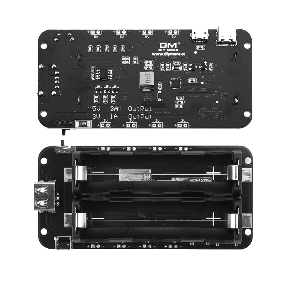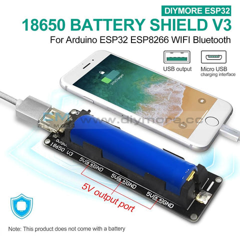
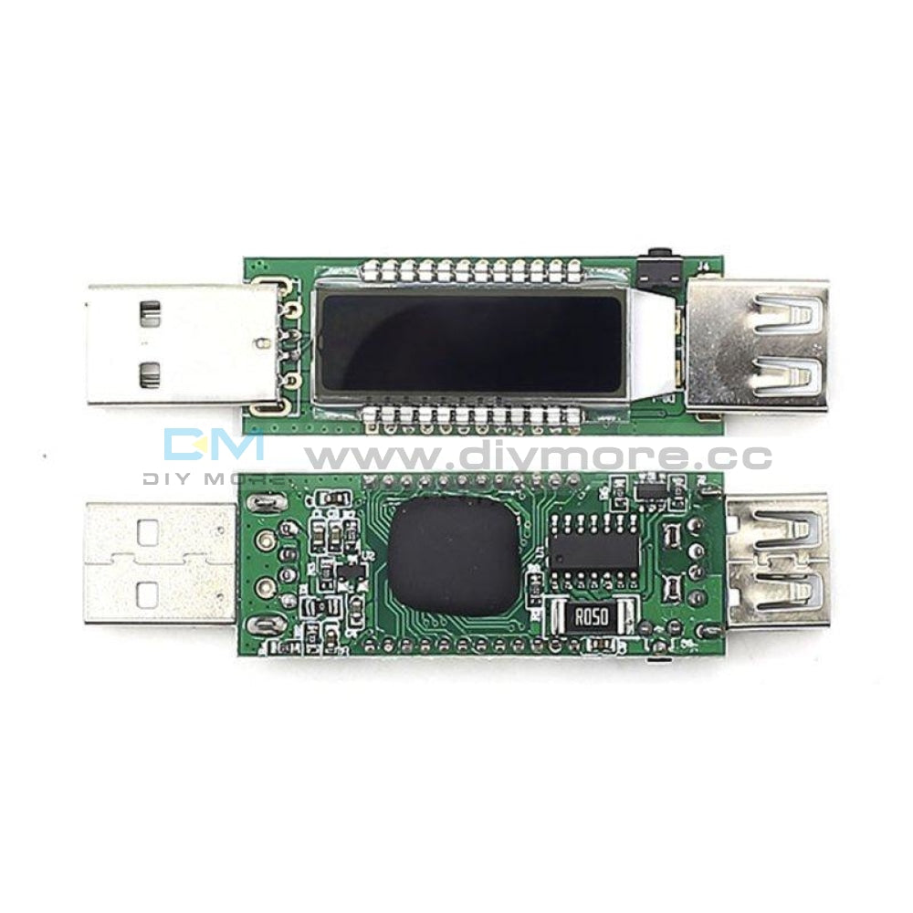
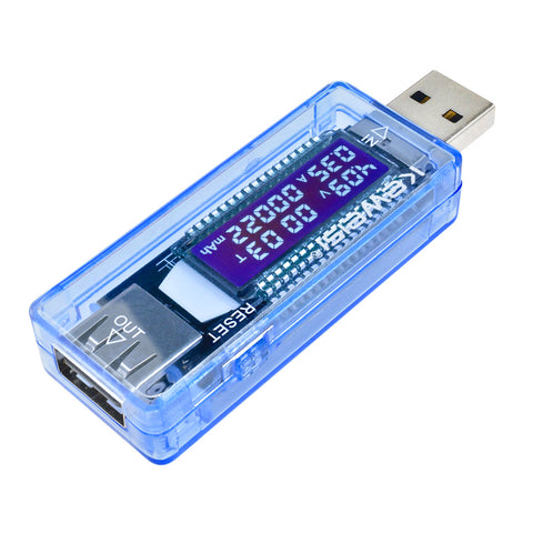 Translation missing: en.products.product.regular_price $7.99{"id":4417209073735,"title":"AC Digital Multifunction Meter Watt Power Volt Amp TTL Current Test Module PZEM 004T With Coil 0 100A 80 260V AC For Arduino","handle":"ac-digital-multifunction-meter-watt-power-volt-amp-ttl-current-test-module-pzem-004t-with-coil-0-100a-80-260v-ac-for-arduino","description":"\u003cdiv\u003e\n\u003cwidget data-widget-type=\"customText\" id=\"23614578\" title=\"011086\" type=\"custom\"\u003e\u003c\/widget\u003e \u003cp\u003e \u003c\/p\u003e \u003cp\u003e \u003c\/p\u003e \u003cp\u003e \u003cimg alt=\"HTB1ZYSui4PI8KJjSspoq6x6MFXaU\" height=\"40\" src=\"https:\/\/ae01.alicdn.com\/kf\/HTB1ZYSui4PI8KJjSspoq6x6MFXaU.jpg\" width=\"950\"\u003e \u003c\/p\u003e \u003cp\u003e \u003c\/p\u003e \u003cdiv\u003e \u003cspan style=\"font-size: 18.0px;\"\u003e\u003cspan style=\"font-family: arial , helvetica , sans-serif;\"\u003e\u003cstrong\u003eModel: PZEM-004T\u003c\/strong\u003e\u003c\/span\u003e\u003c\/span\u003e \u003c\/div\u003e \u003cdiv\u003e \u003c\/div\u003e \u003cdiv\u003e \u003cdiv\u003e \u003cspan style=\"font-size: 18.0px;\"\u003e\u003cspan style=\"font-family: arial , helvetica , sans-serif;\"\u003eOverview\u003c\/span\u003e\u003c\/span\u003e \u003c\/div\u003e \u003cdiv\u003e \u003cspan style=\"font-size: 18.0px;\"\u003e\u003cspan style=\"font-family: arial , helvetica , sans-serif;\"\u003eThis document describes the specification of the PZEM-004T AC communication module,\u003c\/span\u003e\u003c\/span\u003e \u003c\/div\u003e \u003cdiv\u003e \u003cspan style=\"font-size: 18.0px;\"\u003e\u003cspan style=\"font-family: arial , helvetica , sans-serif;\"\u003ethe module is mainly used for measuring AC voltage, current, active power, frequency, power\u003c\/span\u003e\u003c\/span\u003e \u003c\/div\u003e \u003cdiv\u003e \u003cspan style=\"font-size: 18.0px;\"\u003e\u003cspan style=\"font-family: arial , helvetica , sans-serif;\"\u003efactor and active energy, the module is without display function, the data is read through the TTL\u003c\/span\u003e\u003c\/span\u003e \u003c\/div\u003e \u003cdiv\u003e \u003cspan style=\"font-size: 18.0px;\"\u003e\u003cspan style=\"font-family: arial , helvetica , sans-serif;\"\u003einterface.\u003c\/span\u003e\u003c\/span\u003e \u003c\/div\u003e \u003cdiv\u003e \u003cspan style=\"font-size: 18.0px;\"\u003e\u003cspan style=\"font-family: arial , helvetica , sans-serif;\"\u003ePZEM-004T-10A: Measuring Range 10A (Built-in Shunt)\u003c\/span\u003e\u003c\/span\u003e \u003c\/div\u003e \u003cdiv\u003e \u003cspan style=\"font-size: 18.0px;\"\u003e\u003cspan style=\"font-family: arial , helvetica , sans-serif;\"\u003ePZEM-004T-100A: Measuring Range 100A (external transformer)\u003c\/span\u003e\u003c\/span\u003e \u003c\/div\u003e \u003cdiv\u003e \u003cspan style=\"font-size: 18.0px;\"\u003e\u003cspan style=\"font-family: arial , helvetica , sans-serif;\"\u003e1.Function description\u003c\/span\u003e\u003c\/span\u003e \u003c\/div\u003e \u003cdiv\u003e \u003cspan style=\"font-size: 18.0px;\"\u003e\u003cspan style=\"font-family: arial , helvetica , sans-serif;\"\u003e1.1 Voltage\u003c\/span\u003e\u003c\/span\u003e \u003c\/div\u003e \u003cdiv\u003e \u003cspan style=\"font-size: 18.0px;\"\u003e\u003cspan style=\"font-family: arial , helvetica , sans-serif;\"\u003e1.1.1 Measuring range:80~260V\u003c\/span\u003e\u003c\/span\u003e \u003c\/div\u003e \u003cdiv\u003e \u003cspan style=\"font-size: 18.0px;\"\u003e\u003cspan style=\"font-family: arial , helvetica , sans-serif;\"\u003e1.1.2 Resolution: 0.1V\u003c\/span\u003e\u003c\/span\u003e \u003c\/div\u003e \u003cdiv\u003e \u003cspan style=\"font-size: 18.0px;\"\u003e\u003cspan style=\"font-family: arial , helvetica , sans-serif;\"\u003e1.1.3 Measurement accuracy: 0.5%\u003c\/span\u003e\u003c\/span\u003e \u003c\/div\u003e \u003cdiv\u003e \u003cspan style=\"font-size: 18.0px;\"\u003e\u003cspan style=\"font-family: arial , helvetica , sans-serif;\"\u003e1.2 Current\u003c\/span\u003e\u003c\/span\u003e \u003c\/div\u003e \u003cdiv\u003e \u003cspan style=\"font-size: 18.0px;\"\u003e\u003cspan style=\"font-family: arial , helvetica , sans-serif;\"\u003e1.2.1 Measuring range: 0~10A(PZEM-004T-10A); 0~100A(PZEM-004T-100A)\u003c\/span\u003e\u003c\/span\u003e \u003c\/div\u003e \u003cdiv\u003e \u003cspan style=\"font-size: 18.0px;\"\u003e\u003cspan style=\"font-family: arial , helvetica , sans-serif;\"\u003e1.2.2 Starting measure current: 0.01A(PZEM-004T-10A); 0.02A(PZEM-004T-100A)\u003c\/span\u003e\u003c\/span\u003e \u003c\/div\u003e \u003cdiv\u003e \u003cspan style=\"font-size: 18.0px;\"\u003e\u003cspan style=\"font-family: arial , helvetica , sans-serif;\"\u003e1.2.3 Resolution: 0.001A\u003c\/span\u003e\u003c\/span\u003e \u003c\/div\u003e \u003cdiv\u003e \u003cspan style=\"font-size: 18.0px;\"\u003e\u003cspan style=\"font-family: arial , helvetica , sans-serif;\"\u003e1.2.4 Measurement accuracy: 0.5%\u003c\/span\u003e\u003c\/span\u003e \u003c\/div\u003e \u003cdiv\u003e \u003cspan style=\"font-size: 18.0px;\"\u003e\u003cspan style=\"font-family: arial , helvetica , sans-serif;\"\u003e1.3 Active power\u003c\/span\u003e\u003c\/span\u003e \u003c\/div\u003e \u003cdiv\u003e \u003cspan style=\"font-size: 18.0px;\"\u003e\u003cspan style=\"font-family: arial , helvetica , sans-serif;\"\u003e1.3.1 Measuring range: 0~2.3kW(PZEM-004T-10A); 0~23kW(PZEM-004T-100A)\u003c\/span\u003e\u003c\/span\u003e \u003c\/div\u003e \u003cdiv\u003e \u003cspan style=\"font-size: 18.0px;\"\u003e\u003cspan style=\"font-family: arial , helvetica , sans-serif;\"\u003e1.3.2 Starting measure power: 0.4W\u003c\/span\u003e\u003c\/span\u003e \u003c\/div\u003e \u003cdiv\u003e \u003cspan style=\"font-size: 18.0px;\"\u003e\u003cspan style=\"font-family: arial , helvetica , sans-serif;\"\u003e1.3.3 Resolution: 0.1W\u003c\/span\u003e\u003c\/span\u003e \u003c\/div\u003e \u003cdiv\u003e \u003cspan style=\"font-size: 18.0px;\"\u003e\u003cspan style=\"font-family: arial , helvetica , sans-serif;\"\u003e1.3.4 Display format:\u003c\/span\u003e\u003c\/span\u003e \u003c\/div\u003e \u003cdiv\u003e \u003cspan style=\"font-size: 18.0px;\"\u003e\u003cspan style=\"font-family: arial , helvetica , sans-serif;\"\u003e<1000W, it display one decimal, such as: 999.9W\u003c\/span\u003e\u003c\/span\u003e \u003c\/div\u003e \u003cdiv\u003e \u003cspan style=\"font-size: 18.0px;\"\u003e\u003cspan style=\"font-family: arial , helvetica , sans-serif;\"\u003ege1000W, it display only integer, such as: 1000W\u003c\/span\u003e\u003c\/span\u003e \u003c\/div\u003e \u003cdiv\u003e \u003cspan style=\"font-size: 18.0px;\"\u003e\u003cspan style=\"font-family: arial , helvetica , sans-serif;\"\u003e1.3.5 Measurement accuracy: 0.5%\u003c\/span\u003e\u003c\/span\u003e \u003c\/div\u003e \u003cdiv\u003e \u003cspan style=\"font-size: 18.0px;\"\u003e\u003cspan style=\"font-family: arial , helvetica , sans-serif;\"\u003e1.4 Power factor\u003c\/span\u003e\u003c\/span\u003e \u003c\/div\u003e \u003cdiv\u003e \u003cspan style=\"font-size: 18.0px;\"\u003e\u003cspan style=\"font-family: arial , helvetica , sans-serif;\"\u003e1.4.1 Measuring range: 0.00~1.00\u003c\/span\u003e\u003c\/span\u003e \u003c\/div\u003e \u003cdiv\u003e \u003cspan style=\"font-size: 18.0px;\"\u003e\u003cspan style=\"font-family: arial , helvetica , sans-serif;\"\u003e1.4.2 Resolution: 0.01\u003c\/span\u003e\u003c\/span\u003e \u003c\/div\u003e \u003cdiv\u003e \u003cspan style=\"font-size: 18.0px;\"\u003e\u003cspan style=\"font-family: arial , helvetica , sans-serif;\"\u003e1.4.3 Measurement accuracy: 1%\u003c\/span\u003e\u003c\/span\u003e \u003c\/div\u003e \u003cdiv\u003e \u003cspan style=\"font-size: 18.0px;\"\u003e\u003cspan style=\"font-family: arial , helvetica , sans-serif;\"\u003e1.5 Frequency\u003c\/span\u003e\u003c\/span\u003e \u003c\/div\u003e \u003cdiv\u003e \u003cspan style=\"font-size: 18.0px;\"\u003e\u003cspan style=\"font-family: arial , helvetica , sans-serif;\"\u003e1.5.1 Measuring range: 45Hz~65Hz\u003c\/span\u003e\u003c\/span\u003e \u003c\/div\u003e \u003cdiv\u003e \u003cspan style=\"font-size: 18.0px;\"\u003e\u003cspan style=\"font-family: arial , helvetica , sans-serif;\"\u003e1.5.2 Resolution: 0.1Hz\u003c\/span\u003e\u003c\/span\u003e \u003c\/div\u003e \u003cdiv\u003e \u003cspan style=\"font-size: 18.0px;\"\u003e\u003cspan style=\"font-family: arial , helvetica , sans-serif;\"\u003e1.5.3 Measurement accuracy: 0.5%\u003c\/span\u003e\u003c\/span\u003e \u003c\/div\u003e \u003cdiv\u003e \u003cspan style=\"font-size: 18.0px;\"\u003e\u003cspan style=\"font-family: arial , helvetica , sans-serif;\"\u003e1.6 Active energy\u003c\/span\u003e\u003c\/span\u003e \u003c\/div\u003e \u003cdiv\u003e \u003cspan style=\"font-size: 18.0px;\"\u003e\u003cspan style=\"font-family: arial , helvetica , sans-serif;\"\u003e1.6.1 Measuring range: 0~9999.99kWh\u003c\/span\u003e\u003c\/span\u003e \u003c\/div\u003e \u003cdiv\u003e \u003cspan style=\"font-size: 18.0px;\"\u003e\u003cspan style=\"font-family: arial , helvetica , sans-serif;\"\u003e1.6.2 Resolution: 1Wh\u003c\/span\u003e\u003c\/span\u003e \u003c\/div\u003e \u003cdiv\u003e \u003cspan style=\"font-size: 18.0px;\"\u003e\u003cspan style=\"font-family: arial , helvetica , sans-serif;\"\u003e1.6.3 Measurement accuracy: 0.5%\u003c\/span\u003e\u003c\/span\u003e \u003c\/div\u003e \u003cdiv\u003e \u003cspan style=\"font-size: 18.0px;\"\u003e\u003cspan style=\"font-family: arial , helvetica , sans-serif;\"\u003e1.6.4 Display format:\u003c\/span\u003e\u003c\/span\u003e \u003c\/div\u003e \u003cdiv\u003e \u003cspan style=\"font-size: 18.0px;\"\u003e\u003cspan style=\"font-family: arial , helvetica , sans-serif;\"\u003e<10kWh, the display unit is Wh(1kWh=1000Wh), such as: 9999Wh\u003c\/span\u003e\u003c\/span\u003e \u003c\/div\u003e \u003cdiv\u003e \u003cspan style=\"font-size: 18.0px;\"\u003e\u003cspan style=\"font-family: arial , helvetica , sans-serif;\"\u003ege10kWh, the display unit is kWh, such as: 9999.99kWh\u003c\/span\u003e\u003c\/span\u003e \u003c\/div\u003e \u003cdiv\u003e \u003cspan style=\"font-size: 18.0px;\"\u003e\u003cspan style=\"font-family: arial , helvetica , sans-serif;\"\u003e1.6.5 Reset energy: use software to reset.\u003c\/span\u003e\u003c\/span\u003e \u003c\/div\u003e \u003cdiv\u003e \u003cspan style=\"font-size: 18.0px;\"\u003e\u003cspan style=\"font-family: arial , helvetica , sans-serif;\"\u003e1.7 Over power alarm\u003c\/span\u003e\u003c\/span\u003e \u003c\/div\u003e \u003cdiv\u003e \u003cspan style=\"font-size: 18.0px;\"\u003e\u003cspan style=\"font-family: arial , helvetica , sans-serif;\"\u003eActive power threshold can be set, when the measured active power exceeds the threshold, it\u003c\/span\u003e\u003c\/span\u003e \u003c\/div\u003e \u003cdiv\u003e \u003cspan style=\"font-size: 18.0px;\"\u003e\u003cspan style=\"font-family: arial , helvetica , sans-serif;\"\u003ecan alarm\u003c\/span\u003e\u003c\/span\u003e \u003c\/div\u003e \u003cdiv\u003e \u003cspan style=\"font-size: 18.0px;\"\u003e\u003cspan style=\"font-family: arial , helvetica , sans-serif;\"\u003e1.8 Communication interface\u003c\/span\u003e\u003c\/span\u003e \u003c\/div\u003e \u003cdiv\u003e \u003cspan style=\"font-size: 18.0px;\"\u003e\u003cspan style=\"font-family: arial , helvetica , sans-serif;\"\u003eRS485 interface。\u003c\/span\u003e\u003c\/span\u003e \u003c\/div\u003e \u003cdiv\u003e \u003cspan style=\"font-size: 18.0px;\"\u003e\u003cspan style=\"font-family: arial , helvetica , sans-serif;\"\u003e2 Communication protocol\u003c\/span\u003e\u003c\/span\u003e \u003c\/div\u003e \u003cdiv\u003e \u003cspan style=\"font-size: 18.0px;\"\u003e\u003cspan style=\"font-family: arial , helvetica , sans-serif;\"\u003e2.1 Physical layer protocol\u003c\/span\u003e\u003c\/span\u003e \u003c\/div\u003e \u003cdiv\u003e \u003cspan style=\"font-size: 18.0px;\"\u003e\u003cspan style=\"font-family: arial , helvetica , sans-serif;\"\u003ePhysical layer use UART to RS485 communication interface\u003c\/span\u003e\u003c\/span\u003e \u003c\/div\u003e \u003cdiv\u003e \u003cspan style=\"font-size: 18.0px;\"\u003e\u003cspan style=\"font-family: arial , helvetica , sans-serif;\"\u003eBaud rate is 9600, 8 data bits, 1 stop bit, no parity\u003c\/span\u003e\u003c\/span\u003e \u003c\/div\u003e \u003cdiv\u003e \u003cspan style=\"font-size: 18.0px;\"\u003e\u003cspan style=\"font-family: arial , helvetica , sans-serif;\"\u003e2.2 Application layer protocol\u003c\/span\u003e\u003c\/span\u003e \u003c\/div\u003e \u003cdiv\u003e \u003cspan style=\"font-size: 18.0px;\"\u003e\u003cspan style=\"font-family: arial , helvetica , sans-serif;\"\u003eThe application layer use the Modbus-RTU protocol to communicate. At present, it only\u003c\/span\u003e\u003c\/span\u003e \u003c\/div\u003e \u003cdiv\u003e \u003cspan style=\"font-size: 18.0px;\"\u003e\u003cspan style=\"font-family: arial , helvetica , sans-serif;\"\u003esupports function codes such as 0x03 (Read Holding Register), 0x04 (Read Input Register), 0x06\u003c\/span\u003e\u003c\/span\u003e \u003c\/div\u003e \u003cdiv\u003e \u003cspan style=\"font-size: 18.0px;\"\u003e\u003cspan style=\"font-family: arial , helvetica , sans-serif;\"\u003e(Write Single Register), 0x41 (Calibration), 0x42 (Reset energy).etc.\u003c\/span\u003e\u003c\/span\u003e \u003c\/div\u003e \u003cdiv\u003e \u003cspan style=\"font-size: 18.0px;\"\u003e\u003cspan style=\"font-family: arial , helvetica , sans-serif;\"\u003e0x41 function code is only for internal use (address can be only 0xF8), used for factory\u003c\/span\u003e\u003c\/span\u003e \u003c\/div\u003e \u003cdiv\u003e \u003cspan style=\"font-size: 18.0px;\"\u003e\u003cspan style=\"font-family: arial , helvetica , sans-serif;\"\u003ecalibration and return to factory maintenance occasions, after the function code to increase 16-bit\u003c\/span\u003e\u003c\/span\u003e \u003c\/div\u003e \u003cdiv\u003e \u003cspan style=\"font-size: 18.0px;\"\u003e\u003cspan style=\"font-family: arial , helvetica , sans-serif;\"\u003epassword, the default password is 0x3721\u003c\/span\u003e\u003c\/span\u003e \u003c\/div\u003e \u003cdiv\u003e \u003cspan style=\"font-size: 18.0px;\"\u003e\u003cspan style=\"font-family: arial , helvetica , sans-serif;\"\u003eThe address range of the slave is 0x01 ~ 0xF7. The address 0x00 is used as the broadcast\u003c\/span\u003e\u003c\/span\u003e \u003c\/div\u003e \u003cdiv\u003e \u003cspan style=\"font-size: 18.0px;\"\u003e\u003cspan style=\"font-family: arial , helvetica , sans-serif;\"\u003eaddress, the slave does not need to reply the master. The address 0xF8 is used as the general\u003c\/span\u003e\u003c\/span\u003e \u003c\/div\u003e \u003cdiv\u003e \u003cspan style=\"font-size: 18.0px;\"\u003e\u003cspan style=\"font-family: arial , helvetica , sans-serif;\"\u003eaddress, this address can be only used in single-slave environment and can be used for calibration\u003c\/span\u003e\u003c\/span\u003e \u003c\/div\u003e \u003cdiv\u003e \u003cspan style=\"font-size: 18.0px;\"\u003e\u003cspan style=\"font-family: arial , helvetica , sans-serif;\"\u003eetc.operation.\u003c\/span\u003e\u003c\/span\u003e \u003c\/div\u003e \u003cdiv\u003e \u003cspan style=\"font-size: 18.0px;\"\u003e\u003cspan style=\"font-family: arial , helvetica , sans-serif;\"\u003e2.3 Read the measurement result\u003c\/span\u003e\u003c\/span\u003e \u003c\/div\u003e \u003cdiv\u003e \u003cspan style=\"font-size: 18.0px;\"\u003e\u003cspan style=\"font-family: arial , helvetica , sans-serif;\"\u003eThe command format of the master reads the measurement result is(total of 8 bytes):\u003c\/span\u003e\u003c\/span\u003e \u003c\/div\u003e \u003cdiv\u003e \u003cspan style=\"font-size: 18.0px;\"\u003e\u003cspan style=\"font-family: arial , helvetica , sans-serif;\"\u003eSlave Address + 0x04 + Register Address High Byte + Register Address Low Byte + Number\u003c\/span\u003e\u003c\/span\u003e \u003c\/div\u003e \u003cdiv\u003e \u003cspan style=\"font-size: 18.0px;\"\u003e\u003cspan style=\"font-family: arial , helvetica , sans-serif;\"\u003eof Registers High Byte + Number of Registers Low Byte + CRC Check High Byte + CRC Check\u003c\/span\u003e\u003c\/span\u003e \u003c\/div\u003e \u003cdiv\u003e \u003cspan style=\"font-size: 18.0px;\"\u003e\u003cspan style=\"font-family: arial , helvetica , sans-serif;\"\u003eLow Byte.\u003c\/span\u003e\u003c\/span\u003e \u003c\/div\u003e \u003cdiv\u003e \u003cspan style=\"font-size: 18.0px;\"\u003e\u003cspan style=\"font-family: arial , helvetica , sans-serif;\"\u003eThe command format of the reply from the slave is divided into two kinds:\u003c\/span\u003e\u003c\/span\u003e \u003c\/div\u003e \u003cdiv\u003e \u003cspan style=\"font-size: 18.0px;\"\u003e\u003cspan style=\"font-family: arial , helvetica , sans-serif;\"\u003eCorrect Reply: Slave Address + 0x04 + Number of Bytes + Register 1 Data High Byte +\u003c\/span\u003e\u003c\/span\u003e \u003c\/div\u003e \u003cdiv\u003e \u003cspan style=\"font-size: 18.0px;\"\u003e\u003cspan style=\"font-family: arial , helvetica , sans-serif;\"\u003eRegister 1 Data Low Byte + ... + CRC Check High Byte + CRC Check Low Byte\u003c\/span\u003e\u003c\/span\u003e \u003c\/div\u003e \u003cdiv\u003e \u003cspan style=\"font-size: 18.0px;\"\u003e\u003cspan style=\"font-family: arial , helvetica , sans-serif;\"\u003eError Reply: Slave address + 0x84 + Abnormal code + CRC check high byte + CRC check\u003c\/span\u003e\u003c\/span\u003e \u003c\/div\u003e \u003cdiv\u003e \u003cspan style=\"font-size: 18.0px;\"\u003e\u003cspan style=\"font-family: arial , helvetica , sans-serif;\"\u003elow byte\u003c\/span\u003e\u003c\/span\u003e \u003c\/div\u003e \u003cdiv\u003e \u003cspan style=\"font-size: 18.0px;\"\u003e\u003cspan style=\"font-family: arial , helvetica , sans-serif;\"\u003eAbnormal code analyzed as following (the same below)\u003c\/span\u003e\u003c\/span\u003e \u003c\/div\u003e \u003cdiv\u003e \u003cspan style=\"font-size: 18.0px;\"\u003e\u003cspan style=\"font-family: arial , helvetica , sans-serif;\"\u003e⚫ 0x01,Illegal function\u003c\/span\u003e\u003c\/span\u003e \u003c\/div\u003e \u003cdiv\u003e \u003cspan style=\"font-size: 18.0px;\"\u003e\u003cspan style=\"font-family: arial , helvetica , sans-serif;\"\u003e⚫ 0x02,Illegal address\u003c\/span\u003e\u003c\/span\u003e \u003c\/div\u003e \u003cdiv\u003e \u003cspan style=\"font-size: 18.0px;\"\u003e\u003cspan style=\"font-family: arial , helvetica , sans-serif;\"\u003e⚫ 0x03,Illegal data\u003c\/span\u003e\u003c\/span\u003e \u003c\/div\u003e \u003c\/div\u003e \u003cdiv\u003e \u003cspan style=\"font-family: arial , helvetica , sans-serif;font-size: 18.0px;\"\u003e⚫ 0x04,Slave error\u003c\/span\u003e \u003cspan style=\"font-family: arial , helvetica , sans-serif;font-size: 18.0px;\"\u003e \u003c\/span\u003e \u003c\/div\u003e \u003cdiv\u003e \u003cspan style=\"font-family: arial , helvetica , sans-serif;font-size: 18.0px;\"\u003e\u003cimg alt=\"1\" src=\"https:\/\/ae01.alicdn.com\/kf\/HTB1hnE1RzTpK1RjSZKPq6y3UpXaT.jpg\"\u003e\u003c\/span\u003e \u003c\/div\u003e \u003cdiv\u003e \u003c\/div\u003e \u003cdiv\u003e \u003cspan style=\"font-family: arial , helvetica , sans-serif;font-size: 18.0px;\"\u003eFor example, the master sends the following command (CRC check code is replaced by\u003c\/span\u003e \u003c\/div\u003e \u003cdiv\u003e \u003cspan style=\"font-size: 18.0px;\"\u003e\u003cspan style=\"font-family: arial , helvetica , sans-serif;\"\u003e0xHH and 0xLL, the same below)\u003c\/span\u003e\u003c\/span\u003e \u003c\/div\u003e \u003cdiv\u003e \u003cspan style=\"font-size: 18.0px;\"\u003e\u003cspan style=\"font-family: arial , helvetica , sans-serif;\"\u003e0x01 + 0x04 + 0x00 + 0x00 + 0x00 + 0x0A + 0xHH + 0xLL\u003c\/span\u003e\u003c\/span\u003e \u003c\/div\u003e \u003cdiv\u003e \u003cspan style=\"font-size: 18.0px;\"\u003e\u003cspan style=\"font-family: arial , helvetica , sans-serif;\"\u003eIndicates that the master needs to read 10 registers with slave address 0x01 and the start\u003c\/span\u003e\u003c\/span\u003e \u003c\/div\u003e \u003cdiv\u003e \u003cspan style=\"font-size: 18.0px;\"\u003e\u003cspan style=\"font-family: arial , helvetica , sans-serif;\"\u003eaddress of the register is 0x0000\u003c\/span\u003e\u003c\/span\u003e \u003c\/div\u003e \u003cdiv\u003e \u003cspan style=\"font-size: 18.0px;\"\u003e\u003cspan style=\"font-family: arial , helvetica , sans-serif;\"\u003eThe correct reply from the slave is as following:\u003c\/span\u003e\u003c\/span\u003e \u003c\/div\u003e \u003cdiv\u003e \u003cspan style=\"font-size: 18.0px;\"\u003e\u003cspan style=\"font-family: arial , helvetica , sans-serif;\"\u003e0x01 + 0x04 + 0x14 + 0x08 + 0x98 + 0x03 + 0xE8+0x00 + 0x00 +0x08 + 0x98+ 0x00 +\u003c\/span\u003e\u003c\/span\u003e \u003c\/div\u003e \u003cdiv\u003e \u003cspan style=\"font-size: 18.0px;\"\u003e\u003cspan style=\"font-family: arial , helvetica , sans-serif;\"\u003e0x00 + 0x00 + 0x00 + 0x00 + 0x00 + 0x01 + 0xF4 + 0x00 + 0x64 + 0x00 + 0x00 + 0xHH + 0xLL\u003c\/span\u003e\u003c\/span\u003e \u003c\/div\u003e \u003cdiv\u003e \u003cspan style=\"font-size: 18.0px;\"\u003e\u003cspan style=\"font-family: arial , helvetica , sans-serif;\"\u003eThe above data shows\u003c\/span\u003e\u003c\/span\u003e \u003c\/div\u003e \u003cdiv\u003e \u003cspan style=\"font-size: 18.0px;\"\u003e\u003cspan style=\"font-family: arial , helvetica , sans-serif;\"\u003e⚫ Voltage is 0x0898, converted to decimal is 2200, display 220.0V\u003c\/span\u003e\u003c\/span\u003e \u003c\/div\u003e \u003cdiv\u003e \u003cspan style=\"font-size: 18.0px;\"\u003e\u003cspan style=\"font-family: arial , helvetica , sans-serif;\"\u003e⚫ Current is 0x000003E8, converted to decimal is 1000, display 1.000A\u003c\/span\u003e\u003c\/span\u003e \u003c\/div\u003e \u003cdiv\u003e \u003cspan style=\"font-size: 18.0px;\"\u003e\u003cspan style=\"font-family: arial , helvetica , sans-serif;\"\u003e⚫ Power is 0x00000898, converted to decimal is 2200, display 220.0W\u003c\/span\u003e\u003c\/span\u003e \u003c\/div\u003e \u003cdiv\u003e \u003cspan style=\"font-size: 18.0px;\"\u003e\u003cspan style=\"font-family: arial , helvetica , sans-serif;\"\u003e⚫ Energy is 0x00000000, converted to decimal is 0, display 0Wh\u003c\/span\u003e\u003c\/span\u003e \u003c\/div\u003e \u003cdiv\u003e \u003cspan style=\"font-size: 18.0px;\"\u003e\u003cspan style=\"font-family: arial , helvetica , sans-serif;\"\u003e⚫ Frequency is 0x01F4, converted to decimal is 500, display 50.0Hz\u003c\/span\u003e\u003c\/span\u003e \u003c\/div\u003e \u003cdiv\u003e \u003cspan style=\"font-size: 18.0px;\"\u003e\u003cspan style=\"font-family: arial , helvetica , sans-serif;\"\u003e⚫ Power factor is 0x0064, converted to decimal is 100, display 1.00\u003c\/span\u003e\u003c\/span\u003e \u003c\/div\u003e \u003cdiv\u003e \u003cspan style=\"font-size: 18.0px;\"\u003e\u003cspan style=\"font-family: arial , helvetica , sans-serif;\"\u003e⚫ Alarm status is 0x0000, indicates that the current power is lower than the alarm power\u003c\/span\u003e\u003c\/span\u003e \u003c\/div\u003e \u003cdiv\u003e \u003cspan style=\"font-size: 18.0px;\"\u003e\u003cspan style=\"font-family: arial , helvetica , sans-serif;\"\u003ethreshold\u003c\/span\u003e\u003c\/span\u003e \u003c\/div\u003e \u003cdiv\u003e \u003cspan style=\"font-size: 18.0px;\"\u003e\u003cspan style=\"font-family: arial , helvetica , sans-serif;\"\u003e2.4 Read and modify the slave parameters\u003c\/span\u003e\u003c\/span\u003e \u003c\/div\u003e \u003cdiv\u003e \u003cspan style=\"font-size: 18.0px;\"\u003e\u003cspan style=\"font-family: arial , helvetica , sans-serif;\"\u003eAt present,it only supports reading and modifying slave address and power alarm threshold\u003c\/span\u003e\u003c\/span\u003e \u003c\/div\u003e \u003cdiv\u003e \u003cspan style=\"font-size: 18.0px;\"\u003e\u003cspan style=\"font-family: arial , helvetica , sans-serif;\"\u003eThe register is arranged as the following table\u003c\/span\u003e\u003c\/span\u003e \u003c\/div\u003e \u003cdiv\u003e \u003cspan style=\"font-size: 18.0px;\"\u003e\u003cspan style=\"font-family: arial , helvetica , sans-serif;\"\u003e\u003cimg alt=\"2\" src=\"https:\/\/ae01.alicdn.com\/kf\/HTB1QmhWeK3tHKVjSZSgq6x4QFXa5.jpg\"\u003e\u003c\/span\u003e\u003c\/span\u003e \u003c\/div\u003e \u003cdiv\u003e \u003c\/div\u003e \u003cdiv\u003e \u003cspan style=\"font-family: arial , helvetica , sans-serif;font-size: 18.0px;\"\u003eThe command format of the master to read the slave parameters and read the measurement\u003c\/span\u003e \u003c\/div\u003e \u003cdiv\u003e \u003cspan style=\"font-size: 18.0px;\"\u003e\u003cspan style=\"font-family: arial , helvetica , sans-serif;\"\u003eresults are same(descrybed in details in Section 2.3), only need to change the function code from\u003c\/span\u003e\u003c\/span\u003e \u003c\/div\u003e \u003cdiv\u003e \u003cspan style=\"font-size: 18.0px;\"\u003e\u003cspan style=\"font-family: arial , helvetica , sans-serif;\"\u003e0x04 to 0x03.\u003c\/span\u003e\u003c\/span\u003e \u003c\/div\u003e \u003cdiv\u003e \u003cspan style=\"font-size: 18.0px;\"\u003e\u003cspan style=\"font-family: arial , helvetica , sans-serif;\"\u003eThe command format of the master to modify the slave parameters is (total of 8 bytes):\u003c\/span\u003e\u003c\/span\u003e \u003c\/div\u003e \u003cdiv\u003e \u003cspan style=\"font-size: 18.0px;\"\u003e\u003cspan style=\"font-family: arial , helvetica , sans-serif;\"\u003eSlave Address + 0x06 + Register Address High Byte + Register Address Low Byte + Register\u003c\/span\u003e\u003c\/span\u003e \u003c\/div\u003e \u003cdiv\u003e \u003cspan style=\"font-size: 18.0px;\"\u003e\u003cspan style=\"font-family: arial , helvetica , sans-serif;\"\u003eValue High Byte + Register Value Low Byte + CRC Check High Byte + CRC Check Low Byte.\u003c\/span\u003e\u003c\/span\u003e \u003c\/div\u003e \u003cdiv\u003e \u003cspan style=\"font-size: 18.0px;\"\u003e\u003cspan style=\"font-family: arial , helvetica , sans-serif;\"\u003eThe command format of the reply from the slave is divided into two kinds:\u003c\/span\u003e\u003c\/span\u003e \u003c\/div\u003e \u003cdiv\u003e \u003cspan style=\"font-size: 18.0px;\"\u003e\u003cspan style=\"font-family: arial , helvetica , sans-serif;\"\u003eCorrect Response: Slave Address + 0x06 + Number of Bytes + Register Address Low Byte +\u003c\/span\u003e\u003c\/span\u003e \u003c\/div\u003e \u003cdiv\u003e \u003cspan style=\"font-size: 18.0px;\"\u003e\u003cspan style=\"font-family: arial , helvetica , sans-serif;\"\u003eRegister Value High Byte + Register Value Low Byte + CRC Check High Byte + CRC Check Low\u003c\/span\u003e\u003c\/span\u003e \u003c\/div\u003e \u003cdiv\u003e \u003cspan style=\"font-size: 18.0px;\"\u003e\u003cspan style=\"font-family: arial , helvetica , sans-serif;\"\u003eByte.\u003c\/span\u003e\u003c\/span\u003e \u003c\/div\u003e \u003cdiv\u003e \u003cspan style=\"font-size: 18.0px;\"\u003e\u003cspan style=\"font-family: arial , helvetica , sans-serif;\"\u003eError Reply: Slave address + 0x86 + Abnormal code + CRC check high byte + CRC check\u003c\/span\u003e\u003c\/span\u003e \u003c\/div\u003e \u003cdiv\u003e \u003cspan style=\"font-size: 18.0px;\"\u003e\u003cspan style=\"font-family: arial , helvetica , sans-serif;\"\u003elow byte.\u003c\/span\u003e\u003c\/span\u003e \u003c\/div\u003e \u003cdiv\u003e \u003cspan style=\"font-size: 18.0px;\"\u003e\u003cspan style=\"font-family: arial , helvetica , sans-serif;\"\u003eFor example, the master sets the slave's power alarm threshold:\u003c\/span\u003e\u003c\/span\u003e \u003c\/div\u003e \u003cdiv\u003e \u003cspan style=\"font-size: 18.0px;\"\u003e\u003cspan style=\"font-family: arial , helvetica , sans-serif;\"\u003e0x01 + 0x06 + 0x00 + 0x01 + 0x08 + 0xFC + 0xHH + 0xLL\u003c\/span\u003e\u003c\/span\u003e \u003c\/div\u003e \u003cdiv\u003e \u003cspan style=\"font-size: 18.0px;\"\u003e\u003cspan style=\"font-family: arial , helvetica , sans-serif;\"\u003eIndicates that the master needs to set the 0x0001 register (power alarm threshold) to 0x08FC\u003c\/span\u003e\u003c\/span\u003e \u003c\/div\u003e \u003cdiv\u003e \u003cspan style=\"font-size: 18.0px;\"\u003e\u003cspan style=\"font-family: arial , helvetica , sans-serif;\"\u003e(2300W).\u003c\/span\u003e\u003c\/span\u003e \u003c\/div\u003e \u003cdiv\u003e \u003cspan style=\"font-size: 18.0px;\"\u003e\u003cspan style=\"font-family: arial , helvetica , sans-serif;\"\u003eSet up correctly, the slave return to the data which is sent from the master.\u003c\/span\u003e\u003c\/span\u003e \u003c\/div\u003e \u003cdiv\u003e \u003cspan style=\"font-size: 18.0px;\"\u003e\u003cspan style=\"font-family: arial , helvetica , sans-serif;\"\u003eFor example, the master sets the address of the slave\u003c\/span\u003e\u003c\/span\u003e \u003c\/div\u003e \u003cdiv\u003e \u003cspan style=\"font-size: 18.0px;\"\u003e\u003cspan style=\"font-family: arial , helvetica , sans-serif;\"\u003e0x01 + 0x06 + 0x00 + 0x02 + 0x00 + 0x05 + 0xHH + 0xLL\u003c\/span\u003e\u003c\/span\u003e \u003c\/div\u003e \u003cdiv\u003e \u003cspan style=\"font-size: 18.0px;\"\u003e\u003cspan style=\"font-family: arial , helvetica , sans-serif;\"\u003eIndicates that the master needs to set the 0x0002 register (Modbus-RTU address) to 0x0005\u003c\/span\u003e\u003c\/span\u003e \u003c\/div\u003e \u003cdiv\u003e \u003cspan style=\"font-size: 18.0px;\"\u003e\u003cspan style=\"font-family: arial , helvetica , sans-serif;\"\u003eSet up correctly, the slave return to the data which is sent from the master.\u003c\/span\u003e\u003c\/span\u003e \u003c\/div\u003e \u003cdiv\u003e \u003cspan style=\"font-size: 18.0px;\"\u003e\u003cspan style=\"font-family: arial , helvetica , sans-serif;\"\u003e2.5 Reset energy\u003c\/span\u003e\u003c\/span\u003e \u003c\/div\u003e \u003cdiv\u003e \u003cspan style=\"font-size: 18.0px;\"\u003e\u003cspan style=\"font-family: arial , helvetica , sans-serif;\"\u003eThe command format of the master to reset the slave's energy is (total 4 bytes):\u003c\/span\u003e\u003c\/span\u003e \u003c\/div\u003e \u003cdiv\u003e \u003cspan style=\"font-size: 18.0px;\"\u003e\u003cspan style=\"font-family: arial , helvetica , sans-serif;\"\u003eSlave address + 0x42 + CRC check high byte + CRC check low byte.\u003c\/span\u003e\u003c\/span\u003e \u003c\/div\u003e \u003cdiv\u003e \u003cspan style=\"font-size: 18.0px;\"\u003e\u003cspan style=\"font-family: arial , helvetica , sans-serif;\"\u003eCorrect reply: slave address + 0x42 + CRC check high byte + CRC check low byte.\u003c\/span\u003e\u003c\/span\u003e \u003c\/div\u003e \u003cdiv\u003e \u003cspan style=\"font-size: 18.0px;\"\u003e\u003cspan style=\"font-family: arial , helvetica , sans-serif;\"\u003eError Reply: Slave address + 0xC2 + Abnormal code + CRC check high byte + CRC check\u003c\/span\u003e\u003c\/span\u003e \u003c\/div\u003e \u003cdiv\u003e \u003cspan style=\"font-size: 18.0px;\"\u003e\u003cspan style=\"font-family: arial , helvetica , sans-serif;\"\u003elow byte\u003c\/span\u003e\u003c\/span\u003e \u003c\/div\u003e \u003cdiv\u003e \u003cspan style=\"font-size: 18.0px;\"\u003e\u003cspan style=\"font-family: arial , helvetica , sans-serif;\"\u003e2.6 Calibration\u003c\/span\u003e\u003c\/span\u003e \u003c\/div\u003e \u003cdiv\u003e \u003cspan style=\"font-size: 18.0px;\"\u003e\u003cspan style=\"font-family: arial , helvetica , sans-serif;\"\u003eThe command format of the master to calibrate the slave is (total 6 bytes):\u003c\/span\u003e\u003c\/span\u003e \u003c\/div\u003e \u003cdiv\u003e \u003cspan style=\"font-size: 18.0px;\"\u003e\u003cspan style=\"font-family: arial , helvetica , sans-serif;\"\u003e0xF8 + 0x41 + 0x37 + 0x21 + CRC check high byte + CRC check low byte.\u003c\/span\u003e\u003c\/span\u003e \u003c\/div\u003e \u003cdiv\u003e \u003cspan style=\"font-size: 18.0px;\"\u003e\u003cspan style=\"font-family: arial , helvetica , sans-serif;\"\u003eCorrect reply: 0xF8 + 0x41 + 0x37 + 0x21 + CRC check high byte + CRC check low byte.\u003c\/span\u003e\u003c\/span\u003e \u003c\/div\u003e \u003cdiv\u003e \u003cspan style=\"font-size: 18.0px;\"\u003e\u003cspan style=\"font-family: arial , helvetica , sans-serif;\"\u003eError Reply: 0xF8 + 0xC1 + Abnormal code + CRC check high byte + CRC check low byte.\u003c\/span\u003e\u003c\/span\u003e \u003c\/div\u003e \u003cdiv\u003e \u003cspan style=\"font-size: 18.0px;\"\u003e\u003cspan style=\"font-family: arial , helvetica , sans-serif;\"\u003eIt should be noted that the calibration takes 3 to 4 seconds, after the master sends the\u003c\/span\u003e\u003c\/span\u003e \u003c\/div\u003e \u003cdiv\u003e \u003cspan style=\"font-size: 18.0px;\"\u003e\u003cspan style=\"font-family: arial , helvetica , sans-serif;\"\u003ecommand, if the calibration is successful, it will take 3 ~ 4 seconds to receive the response from\u003c\/span\u003e\u003c\/span\u003e \u003c\/div\u003e \u003cdiv\u003e \u003cspan style=\"font-size: 18.0px;\"\u003e\u003cspan style=\"font-family: arial , helvetica , sans-serif;\"\u003ethe slave.\u003c\/span\u003e\u003c\/span\u003e \u003c\/div\u003e \u003cdiv\u003e \u003cspan style=\"font-size: 18.0px;\"\u003e\u003cspan style=\"font-family: arial , helvetica , sans-serif;\"\u003e2.7 CRC check\u003c\/span\u003e\u003c\/span\u003e \u003c\/div\u003e \u003cdiv\u003e \u003cspan style=\"font-size: 18.0px;\"\u003e\u003cspan style=\"font-family: arial , helvetica , sans-serif;\"\u003eCRC check use 16bits format, occupy two bytes, the generator polynomial is X16 + X15 +\u003c\/span\u003e\u003c\/span\u003e \u003c\/div\u003e \u003cdiv\u003e \u003cspan style=\"font-size: 18.0px;\"\u003e\u003cspan style=\"font-family: arial , helvetica , sans-serif;\"\u003eX2 +1, the polynomial value used for calculation is 0xA001.\u003c\/span\u003e\u003c\/span\u003e \u003c\/div\u003e \u003cdiv\u003e \u003cspan style=\"font-size: 18.0px;\"\u003e\u003cspan style=\"font-family: arial , helvetica , sans-serif;\"\u003eThe value of the CRC check is a frame data divide all results of checking all the bytes except\u003c\/span\u003e\u003c\/span\u003e \u003c\/div\u003e \u003cdiv\u003e \u003cspan style=\"font-size: 18.0px;\"\u003e\u003cspan style=\"font-family: arial , helvetica , sans-serif;\"\u003ethe CRC check value.\u003c\/span\u003e\u003c\/span\u003e \u003c\/div\u003e \u003cdiv\u003e \u003cspan style=\"font-size: 18.0px;\"\u003e\u003cspan style=\"font-family: arial , helvetica , sans-serif;\"\u003e3 Functional block diagram\u003c\/span\u003e\u003c\/span\u003e \u003c\/div\u003e \u003cdiv\u003e \u003cspan style=\"font-size: 18.0px;\"\u003e\u003cspan style=\"font-family: arial , helvetica , sans-serif;\"\u003e\u003cimg alt=\"33\" src=\"https:\/\/ae01.alicdn.com\/kf\/HTB1hYMZRrvpK1RjSZFqq6AXUVXap.jpg\"\u003e\u003cimg alt=\"44\" src=\"https:\/\/ae01.alicdn.com\/kf\/HTB1Z_oZRAvoK1RjSZFDq6xY3pXaH.jpg\"\u003e\u003cimg alt=\"55\" src=\"https:\/\/ae01.alicdn.com\/kf\/HTB1WlsVRr2pK1RjSZFsq6yNlXXaH.jpg\"\u003e\u003cimg alt=\"66\" src=\"https:\/\/ae01.alicdn.com\/kf\/HTB1_No5RpzqK1RjSZFvq6AB7VXaA.jpg\"\u003e\u003c\/span\u003e\u003c\/span\u003e \u003c\/div\u003e \u003cdiv\u003e \u003c\/div\u003e \u003cdiv\u003e \u003cspan style=\"font-family: arial , helvetica , sans-serif;font-size: 18.0px;\"\u003e5 Other instructi5.1The TTL interface ohich means, when come it cannot communica5.2 Working temper-20rsquoC ~ +60rsquoC。\u003c\/span\u003e \u003c\/div\u003e \u003cdiv\u003e \u003c\/div\u003e \u003cdiv\u003e \u003c\/div\u003e \u003cdiv\u003e \u003cspan style=\"font-size: 18.0px;\"\u003e\u003cspan style=\"font-family: arial , helvetica , sans-serif;\"\u003ePackage include:\u003c\/span\u003e\u003c\/span\u003e \u003c\/div\u003e \u003cdiv\u003e \u003c\/div\u003e \u003cdiv\u003e \u003c\/div\u003e \u003cdiv\u003e \u003cspan style=\"font-size: 18.0px;\"\u003e\u003cspan style=\"font-family: arial , helvetica , sans-serif;\"\u003e1x Digital Multi-function Meter\u003c\/span\u003e\u003c\/span\u003e \u003c\/div\u003e \u003cdiv\u003e \u003cspan style=\"font-size: 18.0px;\"\u003e\u003cspan style=\"font-family: arial , helvetica , sans-serif;\"\u003e1x Coil\u003c\/span\u003e\u003c\/span\u003e \u003c\/div\u003e \u003cdiv\u003e \u003c\/div\u003e \u003cdiv\u003e \u003c\/div\u003e \u003cdiv\u003e \u003cimg alt=\"HTB1jCuMiY_I8KJjy1Xaq6zsxpXaS\" height=\"40\" src=\"https:\/\/ae01.alicdn.com\/kf\/HTB1jCuMiY_I8KJjy1Xaq6zsxpXaS.jpg\" width=\"950\"\u003e \u003c\/div\u003e \u003cdiv\u003e \u003c\/div\u003e \u003cdiv\u003e \u003c\/div\u003e \u003cdiv\u003e \u003cimg alt=\"[011446 (1)\" src=\"https:\/\/ae01.alicdn.com\/kf\/HTB1mOfRc21H3KVjSZFHq6zKppXaI.jpg\"\u003e\u003cimg alt=\"[011446 (2)\" src=\"https:\/\/ae01.alicdn.com\/kf\/HTB1JB6Rc21H3KVjSZFBq6zSMXXa6.jpg\"\u003e\u003cimg alt=\"[011446 (3)\" src=\"https:\/\/ae01.alicdn.com\/kf\/HTB1Gm6Uc.uF3KVjSZK9q6zVtXXaF.jpg\"\u003e\u003cimg alt=\"[011446 (6)\" src=\"https:\/\/ae01.alicdn.com\/kf\/HTB1mqvSc2WG3KVjSZFgq6zTspXa9.jpg\"\u003e\u003cimg alt=\"[011446 (7)\" src=\"https:\/\/ae01.alicdn.com\/kf\/HTB1nLfVc8GE3KVjSZFhq6AkaFXa2.jpg\"\u003e\u003cimg alt=\"[011446 (8)\" src=\"https:\/\/ae01.alicdn.com\/kf\/HTB1h4r1c8Kw3KVjSZTEq6AuRpXae.jpg\"\u003e\u003cimg alt=\"[011446 (9)\" src=\"https:\/\/ae01.alicdn.com\/kf\/HTB1nA6Sc.WF3KVjSZPhq6xclXXaa.jpg\"\u003e\u003cimg alt=\"[011446 (10)\" src=\"https:\/\/ae01.alicdn.com\/kf\/HTB1YNjSc.KF3KVjSZFEq6xExFXaq.jpg\"\u003e \u003c\/div\u003e \u003cdiv\u003e \u003c\/div\u003e \u003cdiv\u003e \u003c\/div\u003e \u003cdiv\u003e \u003c\/div\u003e \u003cdiv\u003e \u003cimg alt=\"HTB1CoFQi_TI8KJjSsphq6AFppXax\" height=\"40\" src=\"https:\/\/ae01.alicdn.com\/kf\/HTB1CoFQi_TI8KJjSsphq6AFppXax.jpg\" width=\"950\"\u003e \u003c\/div\u003e \u003cdiv\u003e \u003c\/div\u003e \u003cdiv\u003e \u003c\/div\u003e \u003cdiv\u003e \u003cspan style=\"font-size: 18.0px;\"\u003e\u003cspan style=\"font-family: arial , helvetica , sans-serif;\"\u003e\u003cwidget data-widget-type=\"customText\" id=\"22506092\" title=\"catalogue\" type=\"custom\"\u003e\u003c\/widget\u003e\u003c\/span\u003e\u003c\/span\u003e \u003c\/div\u003e \u003cdiv\u003e \u003c\/div\u003e \u003cdiv\u003e \u003c\/div\u003e \u003cdiv\u003e \u003c\/div\u003e \u003cdiv\u003e \u003c\/div\u003e \u003cp style=\"overflow: hidden;height: 1.0px;padding-bottom: 0.0px;padding-top: 0.0px;padding-left: 0.0px;margin: 0.0px;padding-right: 0.0px;\"\u003e \u003c\/p\u003e \u003cdiv style=\"font-size: 24.0px;font-weight: 600;color: #ff0000;padding-bottom: 8.0px;text-align: center;padding-top: 8.0px;padding-left: 8.0px;padding-right: 8.0px;\"\u003e \u003cimg alt=\"HTB1hs.8XfvsK1RjSspdq6AZepXaz\" height=\"1600\" src=\"https:\/\/ae01.alicdn.com\/kf\/HTB1hs.8XfvsK1RjSspdq6AZepXaz.jpg\" width=\"960\"\u003e \u003c\/div\u003e \u003cscript\u003ewindow.adminAccountId=201164481;\u003c\/script\u003e \u003c\/div\u003e","published_at":"2019-12-23T15:11:26+08:00","created_at":"2019-12-23T15:11:39+08:00","vendor":"diymore","type":"GPS\/GPRS Module","tags":[],"price":999,"price_min":999,"price_max":999,"available":true,"price_varies":false,"compare_at_price":null,"compare_at_price_min":0,"compare_at_price_max":0,"compare_at_price_varies":false,"variants":[{"id":31566818148423,"title":"Default Title","option1":"Default Title","option2":null,"option3":null,"sku":"011446","requires_shipping":true,"taxable":false,"featured_image":null,"available":true,"name":"AC Digital Multifunction Meter Watt Power Volt Amp TTL Current Test Module PZEM 004T With Coil 0 100A 80 260V AC For Arduino","public_title":null,"options":["Default Title"],"price":999,"weight":0,"compare_at_price":null,"inventory_management":"shopify","barcode":"","requires_selling_plan":false,"selling_plan_allocations":[],"quantity_rule":{"min":1,"max":null,"increment":1}}],"images":["\/\/www.diymore.cc\/cdn\/shop\/products\/AC-Digital-Multifunction-Meter-Watt-Power-Volt-Amp-TTL-Current-Test-Module-PZEM-004T-With-Coil_851.jpg?v=1588696534","\/\/www.diymore.cc\/cdn\/shop\/products\/AC-Digital-Multifunction-Meter-Watt-Power-Volt-Amp-TTL-Current-Test-Module-PZEM-004T-With-Coil_b4b588d7-f687-4114-be73-503570c06a07_421.jpg?v=1588696534","\/\/www.diymore.cc\/cdn\/shop\/products\/AC-Digital-Multifunction-Meter-Watt-Power-Volt-Amp-TTL-Current-Test-Module-PZEM-004T-With-Coil_239023ee-d161-478e-a487-655519a1f7c9_794.jpg?v=1588696534","\/\/www.diymore.cc\/cdn\/shop\/products\/AC-Digital-Multifunction-Meter-Watt-Power-Volt-Amp-TTL-Current-Test-Module-PZEM-004T-With-Coil_8ab8cbac-3d82-4519-9119-c8aa2fbfb987_307.jpg?v=1588696534","\/\/www.diymore.cc\/cdn\/shop\/products\/AC-Digital-Multifunction-Meter-Watt-Power-Volt-Amp-TTL-Current-Test-Module-PZEM-004T-With-Coil_4b1e267e-fe03-4c68-89ee-8edf13f26f28_642.jpg?v=1588696534","\/\/www.diymore.cc\/cdn\/shop\/products\/AC-Digital-Multifunction-Meter-Watt-Power-Volt-Amp-TTL-Current-Test-Module-PZEM-004T-With-Coil_e3bbf7bf-2c49-474b-b5de-f0b238a2c00e_491.jpg?v=1588696534"],"featured_image":"\/\/www.diymore.cc\/cdn\/shop\/products\/AC-Digital-Multifunction-Meter-Watt-Power-Volt-Amp-TTL-Current-Test-Module-PZEM-004T-With-Coil_851.jpg?v=1588696534","options":["Title"],"media":[{"alt":"Ac Digital Multifunction Meter Watt Power Volt Amp Ttl Current Test Module Pzem 004T With Coil 0","id":6682211123271,"position":1,"preview_image":{"aspect_ratio":1.0,"height":1000,"width":1000,"src":"\/\/www.diymore.cc\/cdn\/shop\/products\/AC-Digital-Multifunction-Meter-Watt-Power-Volt-Amp-TTL-Current-Test-Module-PZEM-004T-With-Coil_851.jpg?v=1588696534"},"aspect_ratio":1.0,"height":1000,"media_type":"image","src":"\/\/www.diymore.cc\/cdn\/shop\/products\/AC-Digital-Multifunction-Meter-Watt-Power-Volt-Amp-TTL-Current-Test-Module-PZEM-004T-With-Coil_851.jpg?v=1588696534","width":1000},{"alt":"Ac Digital Multifunction Meter Watt Power Volt Amp Ttl Current Test Module Pzem 004T With Coil 0","id":6682211352647,"position":2,"preview_image":{"aspect_ratio":1.0,"height":1000,"width":1000,"src":"\/\/www.diymore.cc\/cdn\/shop\/products\/AC-Digital-Multifunction-Meter-Watt-Power-Volt-Amp-TTL-Current-Test-Module-PZEM-004T-With-Coil_b4b588d7-f687-4114-be73-503570c06a07_421.jpg?v=1588696534"},"aspect_ratio":1.0,"height":1000,"media_type":"image","src":"\/\/www.diymore.cc\/cdn\/shop\/products\/AC-Digital-Multifunction-Meter-Watt-Power-Volt-Amp-TTL-Current-Test-Module-PZEM-004T-With-Coil_b4b588d7-f687-4114-be73-503570c06a07_421.jpg?v=1588696534","width":1000},{"alt":"Ac Digital Multifunction Meter Watt Power Volt Amp Ttl Current Test Module Pzem 004T With Coil 0","id":6682211516487,"position":3,"preview_image":{"aspect_ratio":1.0,"height":1000,"width":1000,"src":"\/\/www.diymore.cc\/cdn\/shop\/products\/AC-Digital-Multifunction-Meter-Watt-Power-Volt-Amp-TTL-Current-Test-Module-PZEM-004T-With-Coil_239023ee-d161-478e-a487-655519a1f7c9_794.jpg?v=1588696534"},"aspect_ratio":1.0,"height":1000,"media_type":"image","src":"\/\/www.diymore.cc\/cdn\/shop\/products\/AC-Digital-Multifunction-Meter-Watt-Power-Volt-Amp-TTL-Current-Test-Module-PZEM-004T-With-Coil_239023ee-d161-478e-a487-655519a1f7c9_794.jpg?v=1588696534","width":1000},{"alt":"Ac Digital Multifunction Meter Watt Power Volt Amp Ttl Current Test Module Pzem 004T With Coil 0","id":6682212106311,"position":4,"preview_image":{"aspect_ratio":1.0,"height":1000,"width":1000,"src":"\/\/www.diymore.cc\/cdn\/shop\/products\/AC-Digital-Multifunction-Meter-Watt-Power-Volt-Amp-TTL-Current-Test-Module-PZEM-004T-With-Coil_8ab8cbac-3d82-4519-9119-c8aa2fbfb987_307.jpg?v=1588696534"},"aspect_ratio":1.0,"height":1000,"media_type":"image","src":"\/\/www.diymore.cc\/cdn\/shop\/products\/AC-Digital-Multifunction-Meter-Watt-Power-Volt-Amp-TTL-Current-Test-Module-PZEM-004T-With-Coil_8ab8cbac-3d82-4519-9119-c8aa2fbfb987_307.jpg?v=1588696534","width":1000},{"alt":"Ac Digital Multifunction Meter Watt Power Volt Amp Ttl Current Test Module Pzem 004T With Coil 0","id":6682212466759,"position":5,"preview_image":{"aspect_ratio":1.0,"height":1000,"width":1000,"src":"\/\/www.diymore.cc\/cdn\/shop\/products\/AC-Digital-Multifunction-Meter-Watt-Power-Volt-Amp-TTL-Current-Test-Module-PZEM-004T-With-Coil_4b1e267e-fe03-4c68-89ee-8edf13f26f28_642.jpg?v=1588696534"},"aspect_ratio":1.0,"height":1000,"media_type":"image","src":"\/\/www.diymore.cc\/cdn\/shop\/products\/AC-Digital-Multifunction-Meter-Watt-Power-Volt-Amp-TTL-Current-Test-Module-PZEM-004T-With-Coil_4b1e267e-fe03-4c68-89ee-8edf13f26f28_642.jpg?v=1588696534","width":1000},{"alt":"Ac Digital Multifunction Meter Watt Power Volt Amp Ttl Current Test Module Pzem 004T With Coil 0","id":6682212597831,"position":6,"preview_image":{"aspect_ratio":1.0,"height":1000,"width":1000,"src":"\/\/www.diymore.cc\/cdn\/shop\/products\/AC-Digital-Multifunction-Meter-Watt-Power-Volt-Amp-TTL-Current-Test-Module-PZEM-004T-With-Coil_e3bbf7bf-2c49-474b-b5de-f0b238a2c00e_491.jpg?v=1588696534"},"aspect_ratio":1.0,"height":1000,"media_type":"image","src":"\/\/www.diymore.cc\/cdn\/shop\/products\/AC-Digital-Multifunction-Meter-Watt-Power-Volt-Amp-TTL-Current-Test-Module-PZEM-004T-With-Coil_e3bbf7bf-2c49-474b-b5de-f0b238a2c00e_491.jpg?v=1588696534","width":1000}],"requires_selling_plan":false,"selling_plan_groups":[],"content":"\u003cdiv\u003e\n\u003cwidget data-widget-type=\"customText\" id=\"23614578\" title=\"011086\" type=\"custom\"\u003e\u003c\/widget\u003e \u003cp\u003e \u003c\/p\u003e \u003cp\u003e \u003c\/p\u003e \u003cp\u003e \u003cimg alt=\"HTB1ZYSui4PI8KJjSspoq6x6MFXaU\" height=\"40\" src=\"https:\/\/ae01.alicdn.com\/kf\/HTB1ZYSui4PI8KJjSspoq6x6MFXaU.jpg\" width=\"950\"\u003e \u003c\/p\u003e \u003cp\u003e \u003c\/p\u003e \u003cdiv\u003e \u003cspan style=\"font-size: 18.0px;\"\u003e\u003cspan style=\"font-family: arial , helvetica , sans-serif;\"\u003e\u003cstrong\u003eModel: PZEM-004T\u003c\/strong\u003e\u003c\/span\u003e\u003c\/span\u003e \u003c\/div\u003e \u003cdiv\u003e \u003c\/div\u003e \u003cdiv\u003e \u003cdiv\u003e \u003cspan style=\"font-size: 18.0px;\"\u003e\u003cspan style=\"font-family: arial , helvetica , sans-serif;\"\u003eOverview\u003c\/span\u003e\u003c\/span\u003e \u003c\/div\u003e \u003cdiv\u003e \u003cspan style=\"font-size: 18.0px;\"\u003e\u003cspan style=\"font-family: arial , helvetica , sans-serif;\"\u003eThis document describes the specification of the PZEM-004T AC communication module,\u003c\/span\u003e\u003c\/span\u003e \u003c\/div\u003e \u003cdiv\u003e \u003cspan style=\"font-size: 18.0px;\"\u003e\u003cspan style=\"font-family: arial , helvetica , sans-serif;\"\u003ethe module is mainly used for measuring AC voltage, current, active power, frequency, power\u003c\/span\u003e\u003c\/span\u003e \u003c\/div\u003e \u003cdiv\u003e \u003cspan style=\"font-size: 18.0px;\"\u003e\u003cspan style=\"font-family: arial , helvetica , sans-serif;\"\u003efactor and active energy, the module is without display function, the data is read through the TTL\u003c\/span\u003e\u003c\/span\u003e \u003c\/div\u003e \u003cdiv\u003e \u003cspan style=\"font-size: 18.0px;\"\u003e\u003cspan style=\"font-family: arial , helvetica , sans-serif;\"\u003einterface.\u003c\/span\u003e\u003c\/span\u003e \u003c\/div\u003e \u003cdiv\u003e \u003cspan style=\"font-size: 18.0px;\"\u003e\u003cspan style=\"font-family: arial , helvetica , sans-serif;\"\u003ePZEM-004T-10A: Measuring Range 10A (Built-in Shunt)\u003c\/span\u003e\u003c\/span\u003e \u003c\/div\u003e \u003cdiv\u003e \u003cspan style=\"font-size: 18.0px;\"\u003e\u003cspan style=\"font-family: arial , helvetica , sans-serif;\"\u003ePZEM-004T-100A: Measuring Range 100A (external transformer)\u003c\/span\u003e\u003c\/span\u003e \u003c\/div\u003e \u003cdiv\u003e \u003cspan style=\"font-size: 18.0px;\"\u003e\u003cspan style=\"font-family: arial , helvetica , sans-serif;\"\u003e1.Function description\u003c\/span\u003e\u003c\/span\u003e \u003c\/div\u003e \u003cdiv\u003e \u003cspan style=\"font-size: 18.0px;\"\u003e\u003cspan style=\"font-family: arial , helvetica , sans-serif;\"\u003e1.1 Voltage\u003c\/span\u003e\u003c\/span\u003e \u003c\/div\u003e \u003cdiv\u003e \u003cspan style=\"font-size: 18.0px;\"\u003e\u003cspan style=\"font-family: arial , helvetica , sans-serif;\"\u003e1.1.1 Measuring range:80~260V\u003c\/span\u003e\u003c\/span\u003e \u003c\/div\u003e \u003cdiv\u003e \u003cspan style=\"font-size: 18.0px;\"\u003e\u003cspan style=\"font-family: arial , helvetica , sans-serif;\"\u003e1.1.2 Resolution: 0.1V\u003c\/span\u003e\u003c\/span\u003e \u003c\/div\u003e \u003cdiv\u003e \u003cspan style=\"font-size: 18.0px;\"\u003e\u003cspan style=\"font-family: arial , helvetica , sans-serif;\"\u003e1.1.3 Measurement accuracy: 0.5%\u003c\/span\u003e\u003c\/span\u003e \u003c\/div\u003e \u003cdiv\u003e \u003cspan style=\"font-size: 18.0px;\"\u003e\u003cspan style=\"font-family: arial , helvetica , sans-serif;\"\u003e1.2 Current\u003c\/span\u003e\u003c\/span\u003e \u003c\/div\u003e \u003cdiv\u003e \u003cspan style=\"font-size: 18.0px;\"\u003e\u003cspan style=\"font-family: arial , helvetica , sans-serif;\"\u003e1.2.1 Measuring range: 0~10A(PZEM-004T-10A); 0~100A(PZEM-004T-100A)\u003c\/span\u003e\u003c\/span\u003e \u003c\/div\u003e \u003cdiv\u003e \u003cspan style=\"font-size: 18.0px;\"\u003e\u003cspan style=\"font-family: arial , helvetica , sans-serif;\"\u003e1.2.2 Starting measure current: 0.01A(PZEM-004T-10A); 0.02A(PZEM-004T-100A)\u003c\/span\u003e\u003c\/span\u003e \u003c\/div\u003e \u003cdiv\u003e \u003cspan style=\"font-size: 18.0px;\"\u003e\u003cspan style=\"font-family: arial , helvetica , sans-serif;\"\u003e1.2.3 Resolution: 0.001A\u003c\/span\u003e\u003c\/span\u003e \u003c\/div\u003e \u003cdiv\u003e \u003cspan style=\"font-size: 18.0px;\"\u003e\u003cspan style=\"font-family: arial , helvetica , sans-serif;\"\u003e1.2.4 Measurement accuracy: 0.5%\u003c\/span\u003e\u003c\/span\u003e \u003c\/div\u003e \u003cdiv\u003e \u003cspan style=\"font-size: 18.0px;\"\u003e\u003cspan style=\"font-family: arial , helvetica , sans-serif;\"\u003e1.3 Active power\u003c\/span\u003e\u003c\/span\u003e \u003c\/div\u003e \u003cdiv\u003e \u003cspan style=\"font-size: 18.0px;\"\u003e\u003cspan style=\"font-family: arial , helvetica , sans-serif;\"\u003e1.3.1 Measuring range: 0~2.3kW(PZEM-004T-10A); 0~23kW(PZEM-004T-100A)\u003c\/span\u003e\u003c\/span\u003e \u003c\/div\u003e \u003cdiv\u003e \u003cspan style=\"font-size: 18.0px;\"\u003e\u003cspan style=\"font-family: arial , helvetica , sans-serif;\"\u003e1.3.2 Starting measure power: 0.4W\u003c\/span\u003e\u003c\/span\u003e \u003c\/div\u003e \u003cdiv\u003e \u003cspan style=\"font-size: 18.0px;\"\u003e\u003cspan style=\"font-family: arial , helvetica , sans-serif;\"\u003e1.3.3 Resolution: 0.1W\u003c\/span\u003e\u003c\/span\u003e \u003c\/div\u003e \u003cdiv\u003e \u003cspan style=\"font-size: 18.0px;\"\u003e\u003cspan style=\"font-family: arial , helvetica , sans-serif;\"\u003e1.3.4 Display format:\u003c\/span\u003e\u003c\/span\u003e \u003c\/div\u003e \u003cdiv\u003e \u003cspan style=\"font-size: 18.0px;\"\u003e\u003cspan style=\"font-family: arial , helvetica , sans-serif;\"\u003e<1000W, it display one decimal, such as: 999.9W\u003c\/span\u003e\u003c\/span\u003e \u003c\/div\u003e \u003cdiv\u003e \u003cspan style=\"font-size: 18.0px;\"\u003e\u003cspan style=\"font-family: arial , helvetica , sans-serif;\"\u003ege1000W, it display only integer, such as: 1000W\u003c\/span\u003e\u003c\/span\u003e \u003c\/div\u003e \u003cdiv\u003e \u003cspan style=\"font-size: 18.0px;\"\u003e\u003cspan style=\"font-family: arial , helvetica , sans-serif;\"\u003e1.3.5 Measurement accuracy: 0.5%\u003c\/span\u003e\u003c\/span\u003e \u003c\/div\u003e \u003cdiv\u003e \u003cspan style=\"font-size: 18.0px;\"\u003e\u003cspan style=\"font-family: arial , helvetica , sans-serif;\"\u003e1.4 Power factor\u003c\/span\u003e\u003c\/span\u003e \u003c\/div\u003e \u003cdiv\u003e \u003cspan style=\"font-size: 18.0px;\"\u003e\u003cspan style=\"font-family: arial , helvetica , sans-serif;\"\u003e1.4.1 Measuring range: 0.00~1.00\u003c\/span\u003e\u003c\/span\u003e \u003c\/div\u003e \u003cdiv\u003e \u003cspan style=\"font-size: 18.0px;\"\u003e\u003cspan style=\"font-family: arial , helvetica , sans-serif;\"\u003e1.4.2 Resolution: 0.01\u003c\/span\u003e\u003c\/span\u003e \u003c\/div\u003e \u003cdiv\u003e \u003cspan style=\"font-size: 18.0px;\"\u003e\u003cspan style=\"font-family: arial , helvetica , sans-serif;\"\u003e1.4.3 Measurement accuracy: 1%\u003c\/span\u003e\u003c\/span\u003e \u003c\/div\u003e \u003cdiv\u003e \u003cspan style=\"font-size: 18.0px;\"\u003e\u003cspan style=\"font-family: arial , helvetica , sans-serif;\"\u003e1.5 Frequency\u003c\/span\u003e\u003c\/span\u003e \u003c\/div\u003e \u003cdiv\u003e \u003cspan style=\"font-size: 18.0px;\"\u003e\u003cspan style=\"font-family: arial , helvetica , sans-serif;\"\u003e1.5.1 Measuring range: 45Hz~65Hz\u003c\/span\u003e\u003c\/span\u003e \u003c\/div\u003e \u003cdiv\u003e \u003cspan style=\"font-size: 18.0px;\"\u003e\u003cspan style=\"font-family: arial , helvetica , sans-serif;\"\u003e1.5.2 Resolution: 0.1Hz\u003c\/span\u003e\u003c\/span\u003e \u003c\/div\u003e \u003cdiv\u003e \u003cspan style=\"font-size: 18.0px;\"\u003e\u003cspan style=\"font-family: arial , helvetica , sans-serif;\"\u003e1.5.3 Measurement accuracy: 0.5%\u003c\/span\u003e\u003c\/span\u003e \u003c\/div\u003e \u003cdiv\u003e \u003cspan style=\"font-size: 18.0px;\"\u003e\u003cspan style=\"font-family: arial , helvetica , sans-serif;\"\u003e1.6 Active energy\u003c\/span\u003e\u003c\/span\u003e \u003c\/div\u003e \u003cdiv\u003e \u003cspan style=\"font-size: 18.0px;\"\u003e\u003cspan style=\"font-family: arial , helvetica , sans-serif;\"\u003e1.6.1 Measuring range: 0~9999.99kWh\u003c\/span\u003e\u003c\/span\u003e \u003c\/div\u003e \u003cdiv\u003e \u003cspan style=\"font-size: 18.0px;\"\u003e\u003cspan style=\"font-family: arial , helvetica , sans-serif;\"\u003e1.6.2 Resolution: 1Wh\u003c\/span\u003e\u003c\/span\u003e \u003c\/div\u003e \u003cdiv\u003e \u003cspan style=\"font-size: 18.0px;\"\u003e\u003cspan style=\"font-family: arial , helvetica , sans-serif;\"\u003e1.6.3 Measurement accuracy: 0.5%\u003c\/span\u003e\u003c\/span\u003e \u003c\/div\u003e \u003cdiv\u003e \u003cspan style=\"font-size: 18.0px;\"\u003e\u003cspan style=\"font-family: arial , helvetica , sans-serif;\"\u003e1.6.4 Display format:\u003c\/span\u003e\u003c\/span\u003e \u003c\/div\u003e \u003cdiv\u003e \u003cspan style=\"font-size: 18.0px;\"\u003e\u003cspan style=\"font-family: arial , helvetica , sans-serif;\"\u003e<10kWh, the display unit is Wh(1kWh=1000Wh), such as: 9999Wh\u003c\/span\u003e\u003c\/span\u003e \u003c\/div\u003e \u003cdiv\u003e \u003cspan style=\"font-size: 18.0px;\"\u003e\u003cspan style=\"font-family: arial , helvetica , sans-serif;\"\u003ege10kWh, the display unit is kWh, such as: 9999.99kWh\u003c\/span\u003e\u003c\/span\u003e \u003c\/div\u003e \u003cdiv\u003e \u003cspan style=\"font-size: 18.0px;\"\u003e\u003cspan style=\"font-family: arial , helvetica , sans-serif;\"\u003e1.6.5 Reset energy: use software to reset.\u003c\/span\u003e\u003c\/span\u003e \u003c\/div\u003e \u003cdiv\u003e \u003cspan style=\"font-size: 18.0px;\"\u003e\u003cspan style=\"font-family: arial , helvetica , sans-serif;\"\u003e1.7 Over power alarm\u003c\/span\u003e\u003c\/span\u003e \u003c\/div\u003e \u003cdiv\u003e \u003cspan style=\"font-size: 18.0px;\"\u003e\u003cspan style=\"font-family: arial , helvetica , sans-serif;\"\u003eActive power threshold can be set, when the measured active power exceeds the threshold, it\u003c\/span\u003e\u003c\/span\u003e \u003c\/div\u003e \u003cdiv\u003e \u003cspan style=\"font-size: 18.0px;\"\u003e\u003cspan style=\"font-family: arial , helvetica , sans-serif;\"\u003ecan alarm\u003c\/span\u003e\u003c\/span\u003e \u003c\/div\u003e \u003cdiv\u003e \u003cspan style=\"font-size: 18.0px;\"\u003e\u003cspan style=\"font-family: arial , helvetica , sans-serif;\"\u003e1.8 Communication interface\u003c\/span\u003e\u003c\/span\u003e \u003c\/div\u003e \u003cdiv\u003e \u003cspan style=\"font-size: 18.0px;\"\u003e\u003cspan style=\"font-family: arial , helvetica , sans-serif;\"\u003eRS485 interface。\u003c\/span\u003e\u003c\/span\u003e \u003c\/div\u003e \u003cdiv\u003e \u003cspan style=\"font-size: 18.0px;\"\u003e\u003cspan style=\"font-family: arial , helvetica , sans-serif;\"\u003e2 Communication protocol\u003c\/span\u003e\u003c\/span\u003e \u003c\/div\u003e \u003cdiv\u003e \u003cspan style=\"font-size: 18.0px;\"\u003e\u003cspan style=\"font-family: arial , helvetica , sans-serif;\"\u003e2.1 Physical layer protocol\u003c\/span\u003e\u003c\/span\u003e \u003c\/div\u003e \u003cdiv\u003e \u003cspan style=\"font-size: 18.0px;\"\u003e\u003cspan style=\"font-family: arial , helvetica , sans-serif;\"\u003ePhysical layer use UART to RS485 communication interface\u003c\/span\u003e\u003c\/span\u003e \u003c\/div\u003e \u003cdiv\u003e \u003cspan style=\"font-size: 18.0px;\"\u003e\u003cspan style=\"font-family: arial , helvetica , sans-serif;\"\u003eBaud rate is 9600, 8 data bits, 1 stop bit, no parity\u003c\/span\u003e\u003c\/span\u003e \u003c\/div\u003e \u003cdiv\u003e \u003cspan style=\"font-size: 18.0px;\"\u003e\u003cspan style=\"font-family: arial , helvetica , sans-serif;\"\u003e2.2 Application layer protocol\u003c\/span\u003e\u003c\/span\u003e \u003c\/div\u003e \u003cdiv\u003e \u003cspan style=\"font-size: 18.0px;\"\u003e\u003cspan style=\"font-family: arial , helvetica , sans-serif;\"\u003eThe application layer use the Modbus-RTU protocol to communicate. At present, it only\u003c\/span\u003e\u003c\/span\u003e \u003c\/div\u003e \u003cdiv\u003e \u003cspan style=\"font-size: 18.0px;\"\u003e\u003cspan style=\"font-family: arial , helvetica , sans-serif;\"\u003esupports function codes such as 0x03 (Read Holding Register), 0x04 (Read Input Register), 0x06\u003c\/span\u003e\u003c\/span\u003e \u003c\/div\u003e \u003cdiv\u003e \u003cspan style=\"font-size: 18.0px;\"\u003e\u003cspan style=\"font-family: arial , helvetica , sans-serif;\"\u003e(Write Single Register), 0x41 (Calibration), 0x42 (Reset energy).etc.\u003c\/span\u003e\u003c\/span\u003e \u003c\/div\u003e \u003cdiv\u003e \u003cspan style=\"font-size: 18.0px;\"\u003e\u003cspan style=\"font-family: arial , helvetica , sans-serif;\"\u003e0x41 function code is only for internal use (address can be only 0xF8), used for factory\u003c\/span\u003e\u003c\/span\u003e \u003c\/div\u003e \u003cdiv\u003e \u003cspan style=\"font-size: 18.0px;\"\u003e\u003cspan style=\"font-family: arial , helvetica , sans-serif;\"\u003ecalibration and return to factory maintenance occasions, after the function code to increase 16-bit\u003c\/span\u003e\u003c\/span\u003e \u003c\/div\u003e \u003cdiv\u003e \u003cspan style=\"font-size: 18.0px;\"\u003e\u003cspan style=\"font-family: arial , helvetica , sans-serif;\"\u003epassword, the default password is 0x3721\u003c\/span\u003e\u003c\/span\u003e \u003c\/div\u003e \u003cdiv\u003e \u003cspan style=\"font-size: 18.0px;\"\u003e\u003cspan style=\"font-family: arial , helvetica , sans-serif;\"\u003eThe address range of the slave is 0x01 ~ 0xF7. The address 0x00 is used as the broadcast\u003c\/span\u003e\u003c\/span\u003e \u003c\/div\u003e \u003cdiv\u003e \u003cspan style=\"font-size: 18.0px;\"\u003e\u003cspan style=\"font-family: arial , helvetica , sans-serif;\"\u003eaddress, the slave does not need to reply the master. The address 0xF8 is used as the general\u003c\/span\u003e\u003c\/span\u003e \u003c\/div\u003e \u003cdiv\u003e \u003cspan style=\"font-size: 18.0px;\"\u003e\u003cspan style=\"font-family: arial , helvetica , sans-serif;\"\u003eaddress, this address can be only used in single-slave environment and can be used for calibration\u003c\/span\u003e\u003c\/span\u003e \u003c\/div\u003e \u003cdiv\u003e \u003cspan style=\"font-size: 18.0px;\"\u003e\u003cspan style=\"font-family: arial , helvetica , sans-serif;\"\u003eetc.operation.\u003c\/span\u003e\u003c\/span\u003e \u003c\/div\u003e \u003cdiv\u003e \u003cspan style=\"font-size: 18.0px;\"\u003e\u003cspan style=\"font-family: arial , helvetica , sans-serif;\"\u003e2.3 Read the measurement result\u003c\/span\u003e\u003c\/span\u003e \u003c\/div\u003e \u003cdiv\u003e \u003cspan style=\"font-size: 18.0px;\"\u003e\u003cspan style=\"font-family: arial , helvetica , sans-serif;\"\u003eThe command format of the master reads the measurement result is(total of 8 bytes):\u003c\/span\u003e\u003c\/span\u003e \u003c\/div\u003e \u003cdiv\u003e \u003cspan style=\"font-size: 18.0px;\"\u003e\u003cspan style=\"font-family: arial , helvetica , sans-serif;\"\u003eSlave Address + 0x04 + Register Address High Byte + Register Address Low Byte + Number\u003c\/span\u003e\u003c\/span\u003e \u003c\/div\u003e \u003cdiv\u003e \u003cspan style=\"font-size: 18.0px;\"\u003e\u003cspan style=\"font-family: arial , helvetica , sans-serif;\"\u003eof Registers High Byte + Number of Registers Low Byte + CRC Check High Byte + CRC Check\u003c\/span\u003e\u003c\/span\u003e \u003c\/div\u003e \u003cdiv\u003e \u003cspan style=\"font-size: 18.0px;\"\u003e\u003cspan style=\"font-family: arial , helvetica , sans-serif;\"\u003eLow Byte.\u003c\/span\u003e\u003c\/span\u003e \u003c\/div\u003e \u003cdiv\u003e \u003cspan style=\"font-size: 18.0px;\"\u003e\u003cspan style=\"font-family: arial , helvetica , sans-serif;\"\u003eThe command format of the reply from the slave is divided into two kinds:\u003c\/span\u003e\u003c\/span\u003e \u003c\/div\u003e \u003cdiv\u003e \u003cspan style=\"font-size: 18.0px;\"\u003e\u003cspan style=\"font-family: arial , helvetica , sans-serif;\"\u003eCorrect Reply: Slave Address + 0x04 + Number of Bytes + Register 1 Data High Byte +\u003c\/span\u003e\u003c\/span\u003e \u003c\/div\u003e \u003cdiv\u003e \u003cspan style=\"font-size: 18.0px;\"\u003e\u003cspan style=\"font-family: arial , helvetica , sans-serif;\"\u003eRegister 1 Data Low Byte + ... + CRC Check High Byte + CRC Check Low Byte\u003c\/span\u003e\u003c\/span\u003e \u003c\/div\u003e \u003cdiv\u003e \u003cspan style=\"font-size: 18.0px;\"\u003e\u003cspan style=\"font-family: arial , helvetica , sans-serif;\"\u003eError Reply: Slave address + 0x84 + Abnormal code + CRC check high byte + CRC check\u003c\/span\u003e\u003c\/span\u003e \u003c\/div\u003e \u003cdiv\u003e \u003cspan style=\"font-size: 18.0px;\"\u003e\u003cspan style=\"font-family: arial , helvetica , sans-serif;\"\u003elow byte\u003c\/span\u003e\u003c\/span\u003e \u003c\/div\u003e \u003cdiv\u003e \u003cspan style=\"font-size: 18.0px;\"\u003e\u003cspan style=\"font-family: arial , helvetica , sans-serif;\"\u003eAbnormal code analyzed as following (the same below)\u003c\/span\u003e\u003c\/span\u003e \u003c\/div\u003e \u003cdiv\u003e \u003cspan style=\"font-size: 18.0px;\"\u003e\u003cspan style=\"font-family: arial , helvetica , sans-serif;\"\u003e⚫ 0x01,Illegal function\u003c\/span\u003e\u003c\/span\u003e \u003c\/div\u003e \u003cdiv\u003e \u003cspan style=\"font-size: 18.0px;\"\u003e\u003cspan style=\"font-family: arial , helvetica , sans-serif;\"\u003e⚫ 0x02,Illegal address\u003c\/span\u003e\u003c\/span\u003e \u003c\/div\u003e \u003cdiv\u003e \u003cspan style=\"font-size: 18.0px;\"\u003e\u003cspan style=\"font-family: arial , helvetica , sans-serif;\"\u003e⚫ 0x03,Illegal data\u003c\/span\u003e\u003c\/span\u003e \u003c\/div\u003e \u003c\/div\u003e \u003cdiv\u003e \u003cspan style=\"font-family: arial , helvetica , sans-serif;font-size: 18.0px;\"\u003e⚫ 0x04,Slave error\u003c\/span\u003e \u003cspan style=\"font-family: arial , helvetica , sans-serif;font-size: 18.0px;\"\u003e \u003c\/span\u003e \u003c\/div\u003e \u003cdiv\u003e \u003cspan style=\"font-family: arial , helvetica , sans-serif;font-size: 18.0px;\"\u003e\u003cimg alt=\"1\" src=\"https:\/\/ae01.alicdn.com\/kf\/HTB1hnE1RzTpK1RjSZKPq6y3UpXaT.jpg\"\u003e\u003c\/span\u003e \u003c\/div\u003e \u003cdiv\u003e \u003c\/div\u003e \u003cdiv\u003e \u003cspan style=\"font-family: arial , helvetica , sans-serif;font-size: 18.0px;\"\u003eFor example, the master sends the following command (CRC check code is replaced by\u003c\/span\u003e \u003c\/div\u003e \u003cdiv\u003e \u003cspan style=\"font-size: 18.0px;\"\u003e\u003cspan style=\"font-family: arial , helvetica , sans-serif;\"\u003e0xHH and 0xLL, the same below)\u003c\/span\u003e\u003c\/span\u003e \u003c\/div\u003e \u003cdiv\u003e \u003cspan style=\"font-size: 18.0px;\"\u003e\u003cspan style=\"font-family: arial , helvetica , sans-serif;\"\u003e0x01 + 0x04 + 0x00 + 0x00 + 0x00 + 0x0A + 0xHH + 0xLL\u003c\/span\u003e\u003c\/span\u003e \u003c\/div\u003e \u003cdiv\u003e \u003cspan style=\"font-size: 18.0px;\"\u003e\u003cspan style=\"font-family: arial , helvetica , sans-serif;\"\u003eIndicates that the master needs to read 10 registers with slave address 0x01 and the start\u003c\/span\u003e\u003c\/span\u003e \u003c\/div\u003e \u003cdiv\u003e \u003cspan style=\"font-size: 18.0px;\"\u003e\u003cspan style=\"font-family: arial , helvetica , sans-serif;\"\u003eaddress of the register is 0x0000\u003c\/span\u003e\u003c\/span\u003e \u003c\/div\u003e \u003cdiv\u003e \u003cspan style=\"font-size: 18.0px;\"\u003e\u003cspan style=\"font-family: arial , helvetica , sans-serif;\"\u003eThe correct reply from the slave is as following:\u003c\/span\u003e\u003c\/span\u003e \u003c\/div\u003e \u003cdiv\u003e \u003cspan style=\"font-size: 18.0px;\"\u003e\u003cspan style=\"font-family: arial , helvetica , sans-serif;\"\u003e0x01 + 0x04 + 0x14 + 0x08 + 0x98 + 0x03 + 0xE8+0x00 + 0x00 +0x08 + 0x98+ 0x00 +\u003c\/span\u003e\u003c\/span\u003e \u003c\/div\u003e \u003cdiv\u003e \u003cspan style=\"font-size: 18.0px;\"\u003e\u003cspan style=\"font-family: arial , helvetica , sans-serif;\"\u003e0x00 + 0x00 + 0x00 + 0x00 + 0x00 + 0x01 + 0xF4 + 0x00 + 0x64 + 0x00 + 0x00 + 0xHH + 0xLL\u003c\/span\u003e\u003c\/span\u003e \u003c\/div\u003e \u003cdiv\u003e \u003cspan style=\"font-size: 18.0px;\"\u003e\u003cspan style=\"font-family: arial , helvetica , sans-serif;\"\u003eThe above data shows\u003c\/span\u003e\u003c\/span\u003e \u003c\/div\u003e \u003cdiv\u003e \u003cspan style=\"font-size: 18.0px;\"\u003e\u003cspan style=\"font-family: arial , helvetica , sans-serif;\"\u003e⚫ Voltage is 0x0898, converted to decimal is 2200, display 220.0V\u003c\/span\u003e\u003c\/span\u003e \u003c\/div\u003e \u003cdiv\u003e \u003cspan style=\"font-size: 18.0px;\"\u003e\u003cspan style=\"font-family: arial , helvetica , sans-serif;\"\u003e⚫ Current is 0x000003E8, converted to decimal is 1000, display 1.000A\u003c\/span\u003e\u003c\/span\u003e \u003c\/div\u003e \u003cdiv\u003e \u003cspan style=\"font-size: 18.0px;\"\u003e\u003cspan style=\"font-family: arial , helvetica , sans-serif;\"\u003e⚫ Power is 0x00000898, converted to decimal is 2200, display 220.0W\u003c\/span\u003e\u003c\/span\u003e \u003c\/div\u003e \u003cdiv\u003e \u003cspan style=\"font-size: 18.0px;\"\u003e\u003cspan style=\"font-family: arial , helvetica , sans-serif;\"\u003e⚫ Energy is 0x00000000, converted to decimal is 0, display 0Wh\u003c\/span\u003e\u003c\/span\u003e \u003c\/div\u003e \u003cdiv\u003e \u003cspan style=\"font-size: 18.0px;\"\u003e\u003cspan style=\"font-family: arial , helvetica , sans-serif;\"\u003e⚫ Frequency is 0x01F4, converted to decimal is 500, display 50.0Hz\u003c\/span\u003e\u003c\/span\u003e \u003c\/div\u003e \u003cdiv\u003e \u003cspan style=\"font-size: 18.0px;\"\u003e\u003cspan style=\"font-family: arial , helvetica , sans-serif;\"\u003e⚫ Power factor is 0x0064, converted to decimal is 100, display 1.00\u003c\/span\u003e\u003c\/span\u003e \u003c\/div\u003e \u003cdiv\u003e \u003cspan style=\"font-size: 18.0px;\"\u003e\u003cspan style=\"font-family: arial , helvetica , sans-serif;\"\u003e⚫ Alarm status is 0x0000, indicates that the current power is lower than the alarm power\u003c\/span\u003e\u003c\/span\u003e \u003c\/div\u003e \u003cdiv\u003e \u003cspan style=\"font-size: 18.0px;\"\u003e\u003cspan style=\"font-family: arial , helvetica , sans-serif;\"\u003ethreshold\u003c\/span\u003e\u003c\/span\u003e \u003c\/div\u003e \u003cdiv\u003e \u003cspan style=\"font-size: 18.0px;\"\u003e\u003cspan style=\"font-family: arial , helvetica , sans-serif;\"\u003e2.4 Read and modify the slave parameters\u003c\/span\u003e\u003c\/span\u003e \u003c\/div\u003e \u003cdiv\u003e \u003cspan style=\"font-size: 18.0px;\"\u003e\u003cspan style=\"font-family: arial , helvetica , sans-serif;\"\u003eAt present,it only supports reading and modifying slave address and power alarm threshold\u003c\/span\u003e\u003c\/span\u003e \u003c\/div\u003e \u003cdiv\u003e \u003cspan style=\"font-size: 18.0px;\"\u003e\u003cspan style=\"font-family: arial , helvetica , sans-serif;\"\u003eThe register is arranged as the following table\u003c\/span\u003e\u003c\/span\u003e \u003c\/div\u003e \u003cdiv\u003e \u003cspan style=\"font-size: 18.0px;\"\u003e\u003cspan style=\"font-family: arial , helvetica , sans-serif;\"\u003e\u003cimg alt=\"2\" src=\"https:\/\/ae01.alicdn.com\/kf\/HTB1QmhWeK3tHKVjSZSgq6x4QFXa5.jpg\"\u003e\u003c\/span\u003e\u003c\/span\u003e \u003c\/div\u003e \u003cdiv\u003e \u003c\/div\u003e \u003cdiv\u003e \u003cspan style=\"font-family: arial , helvetica , sans-serif;font-size: 18.0px;\"\u003eThe command format of the master to read the slave parameters and read the measurement\u003c\/span\u003e \u003c\/div\u003e \u003cdiv\u003e \u003cspan style=\"font-size: 18.0px;\"\u003e\u003cspan style=\"font-family: arial , helvetica , sans-serif;\"\u003eresults are same(descrybed in details in Section 2.3), only need to change the function code from\u003c\/span\u003e\u003c\/span\u003e \u003c\/div\u003e \u003cdiv\u003e \u003cspan style=\"font-size: 18.0px;\"\u003e\u003cspan style=\"font-family: arial , helvetica , sans-serif;\"\u003e0x04 to 0x03.\u003c\/span\u003e\u003c\/span\u003e \u003c\/div\u003e \u003cdiv\u003e \u003cspan style=\"font-size: 18.0px;\"\u003e\u003cspan style=\"font-family: arial , helvetica , sans-serif;\"\u003eThe command format of the master to modify the slave parameters is (total of 8 bytes):\u003c\/span\u003e\u003c\/span\u003e \u003c\/div\u003e \u003cdiv\u003e \u003cspan style=\"font-size: 18.0px;\"\u003e\u003cspan style=\"font-family: arial , helvetica , sans-serif;\"\u003eSlave Address + 0x06 + Register Address High Byte + Register Address Low Byte + Register\u003c\/span\u003e\u003c\/span\u003e \u003c\/div\u003e \u003cdiv\u003e \u003cspan style=\"font-size: 18.0px;\"\u003e\u003cspan style=\"font-family: arial , helvetica , sans-serif;\"\u003eValue High Byte + Register Value Low Byte + CRC Check High Byte + CRC Check Low Byte.\u003c\/span\u003e\u003c\/span\u003e \u003c\/div\u003e \u003cdiv\u003e \u003cspan style=\"font-size: 18.0px;\"\u003e\u003cspan style=\"font-family: arial , helvetica , sans-serif;\"\u003eThe command format of the reply from the slave is divided into two kinds:\u003c\/span\u003e\u003c\/span\u003e \u003c\/div\u003e \u003cdiv\u003e \u003cspan style=\"font-size: 18.0px;\"\u003e\u003cspan style=\"font-family: arial , helvetica , sans-serif;\"\u003eCorrect Response: Slave Address + 0x06 + Number of Bytes + Register Address Low Byte +\u003c\/span\u003e\u003c\/span\u003e \u003c\/div\u003e \u003cdiv\u003e \u003cspan style=\"font-size: 18.0px;\"\u003e\u003cspan style=\"font-family: arial , helvetica , sans-serif;\"\u003eRegister Value High Byte + Register Value Low Byte + CRC Check High Byte + CRC Check Low\u003c\/span\u003e\u003c\/span\u003e \u003c\/div\u003e \u003cdiv\u003e \u003cspan style=\"font-size: 18.0px;\"\u003e\u003cspan style=\"font-family: arial , helvetica , sans-serif;\"\u003eByte.\u003c\/span\u003e\u003c\/span\u003e \u003c\/div\u003e \u003cdiv\u003e \u003cspan style=\"font-size: 18.0px;\"\u003e\u003cspan style=\"font-family: arial , helvetica , sans-serif;\"\u003eError Reply: Slave address + 0x86 + Abnormal code + CRC check high byte + CRC check\u003c\/span\u003e\u003c\/span\u003e \u003c\/div\u003e \u003cdiv\u003e \u003cspan style=\"font-size: 18.0px;\"\u003e\u003cspan style=\"font-family: arial , helvetica , sans-serif;\"\u003elow byte.\u003c\/span\u003e\u003c\/span\u003e \u003c\/div\u003e \u003cdiv\u003e \u003cspan style=\"font-size: 18.0px;\"\u003e\u003cspan style=\"font-family: arial , helvetica , sans-serif;\"\u003eFor example, the master sets the slave's power alarm threshold:\u003c\/span\u003e\u003c\/span\u003e \u003c\/div\u003e \u003cdiv\u003e \u003cspan style=\"font-size: 18.0px;\"\u003e\u003cspan style=\"font-family: arial , helvetica , sans-serif;\"\u003e0x01 + 0x06 + 0x00 + 0x01 + 0x08 + 0xFC + 0xHH + 0xLL\u003c\/span\u003e\u003c\/span\u003e \u003c\/div\u003e \u003cdiv\u003e \u003cspan style=\"font-size: 18.0px;\"\u003e\u003cspan style=\"font-family: arial , helvetica , sans-serif;\"\u003eIndicates that the master needs to set the 0x0001 register (power alarm threshold) to 0x08FC\u003c\/span\u003e\u003c\/span\u003e \u003c\/div\u003e \u003cdiv\u003e \u003cspan style=\"font-size: 18.0px;\"\u003e\u003cspan style=\"font-family: arial , helvetica , sans-serif;\"\u003e(2300W).\u003c\/span\u003e\u003c\/span\u003e \u003c\/div\u003e \u003cdiv\u003e \u003cspan style=\"font-size: 18.0px;\"\u003e\u003cspan style=\"font-family: arial , helvetica , sans-serif;\"\u003eSet up correctly, the slave return to the data which is sent from the master.\u003c\/span\u003e\u003c\/span\u003e \u003c\/div\u003e \u003cdiv\u003e \u003cspan style=\"font-size: 18.0px;\"\u003e\u003cspan style=\"font-family: arial , helvetica , sans-serif;\"\u003eFor example, the master sets the address of the slave\u003c\/span\u003e\u003c\/span\u003e \u003c\/div\u003e \u003cdiv\u003e \u003cspan style=\"font-size: 18.0px;\"\u003e\u003cspan style=\"font-family: arial , helvetica , sans-serif;\"\u003e0x01 + 0x06 + 0x00 + 0x02 + 0x00 + 0x05 + 0xHH + 0xLL\u003c\/span\u003e\u003c\/span\u003e \u003c\/div\u003e \u003cdiv\u003e \u003cspan style=\"font-size: 18.0px;\"\u003e\u003cspan style=\"font-family: arial , helvetica , sans-serif;\"\u003eIndicates that the master needs to set the 0x0002 register (Modbus-RTU address) to 0x0005\u003c\/span\u003e\u003c\/span\u003e \u003c\/div\u003e \u003cdiv\u003e \u003cspan style=\"font-size: 18.0px;\"\u003e\u003cspan style=\"font-family: arial , helvetica , sans-serif;\"\u003eSet up correctly, the slave return to the data which is sent from the master.\u003c\/span\u003e\u003c\/span\u003e \u003c\/div\u003e \u003cdiv\u003e \u003cspan style=\"font-size: 18.0px;\"\u003e\u003cspan style=\"font-family: arial , helvetica , sans-serif;\"\u003e2.5 Reset energy\u003c\/span\u003e\u003c\/span\u003e \u003c\/div\u003e \u003cdiv\u003e \u003cspan style=\"font-size: 18.0px;\"\u003e\u003cspan style=\"font-family: arial , helvetica , sans-serif;\"\u003eThe command format of the master to reset the slave's energy is (total 4 bytes):\u003c\/span\u003e\u003c\/span\u003e \u003c\/div\u003e \u003cdiv\u003e \u003cspan style=\"font-size: 18.0px;\"\u003e\u003cspan style=\"font-family: arial , helvetica , sans-serif;\"\u003eSlave address + 0x42 + CRC check high byte + CRC check low byte.\u003c\/span\u003e\u003c\/span\u003e \u003c\/div\u003e \u003cdiv\u003e \u003cspan style=\"font-size: 18.0px;\"\u003e\u003cspan style=\"font-family: arial , helvetica , sans-serif;\"\u003eCorrect reply: slave address + 0x42 + CRC check high byte + CRC check low byte.\u003c\/span\u003e\u003c\/span\u003e \u003c\/div\u003e \u003cdiv\u003e \u003cspan style=\"font-size: 18.0px;\"\u003e\u003cspan style=\"font-family: arial , helvetica , sans-serif;\"\u003eError Reply: Slave address + 0xC2 + Abnormal code + CRC check high byte + CRC check\u003c\/span\u003e\u003c\/span\u003e \u003c\/div\u003e \u003cdiv\u003e \u003cspan style=\"font-size: 18.0px;\"\u003e\u003cspan style=\"font-family: arial , helvetica , sans-serif;\"\u003elow byte\u003c\/span\u003e\u003c\/span\u003e \u003c\/div\u003e \u003cdiv\u003e \u003cspan style=\"font-size: 18.0px;\"\u003e\u003cspan style=\"font-family: arial , helvetica , sans-serif;\"\u003e2.6 Calibration\u003c\/span\u003e\u003c\/span\u003e \u003c\/div\u003e \u003cdiv\u003e \u003cspan style=\"font-size: 18.0px;\"\u003e\u003cspan style=\"font-family: arial , helvetica , sans-serif;\"\u003eThe command format of the master to calibrate the slave is (total 6 bytes):\u003c\/span\u003e\u003c\/span\u003e \u003c\/div\u003e \u003cdiv\u003e \u003cspan style=\"font-size: 18.0px;\"\u003e\u003cspan style=\"font-family: arial , helvetica , sans-serif;\"\u003e0xF8 + 0x41 + 0x37 + 0x21 + CRC check high byte + CRC check low byte.\u003c\/span\u003e\u003c\/span\u003e \u003c\/div\u003e \u003cdiv\u003e \u003cspan style=\"font-size: 18.0px;\"\u003e\u003cspan style=\"font-family: arial , helvetica , sans-serif;\"\u003eCorrect reply: 0xF8 + 0x41 + 0x37 + 0x21 + CRC check high byte + CRC check low byte.\u003c\/span\u003e\u003c\/span\u003e \u003c\/div\u003e \u003cdiv\u003e \u003cspan style=\"font-size: 18.0px;\"\u003e\u003cspan style=\"font-family: arial , helvetica , sans-serif;\"\u003eError Reply: 0xF8 + 0xC1 + Abnormal code + CRC check high byte + CRC check low byte.\u003c\/span\u003e\u003c\/span\u003e \u003c\/div\u003e \u003cdiv\u003e \u003cspan style=\"font-size: 18.0px;\"\u003e\u003cspan style=\"font-family: arial , helvetica , sans-serif;\"\u003eIt should be noted that the calibration takes 3 to 4 seconds, after the master sends the\u003c\/span\u003e\u003c\/span\u003e \u003c\/div\u003e \u003cdiv\u003e \u003cspan style=\"font-size: 18.0px;\"\u003e\u003cspan style=\"font-family: arial , helvetica , sans-serif;\"\u003ecommand, if the calibration is successful, it will take 3 ~ 4 seconds to receive the response from\u003c\/span\u003e\u003c\/span\u003e \u003c\/div\u003e \u003cdiv\u003e \u003cspan style=\"font-size: 18.0px;\"\u003e\u003cspan style=\"font-family: arial , helvetica , sans-serif;\"\u003ethe slave.\u003c\/span\u003e\u003c\/span\u003e \u003c\/div\u003e \u003cdiv\u003e \u003cspan style=\"font-size: 18.0px;\"\u003e\u003cspan style=\"font-family: arial , helvetica , sans-serif;\"\u003e2.7 CRC check\u003c\/span\u003e\u003c\/span\u003e \u003c\/div\u003e \u003cdiv\u003e \u003cspan style=\"font-size: 18.0px;\"\u003e\u003cspan style=\"font-family: arial , helvetica , sans-serif;\"\u003eCRC check use 16bits format, occupy two bytes, the generator polynomial is X16 + X15 +\u003c\/span\u003e\u003c\/span\u003e \u003c\/div\u003e \u003cdiv\u003e \u003cspan style=\"font-size: 18.0px;\"\u003e\u003cspan style=\"font-family: arial , helvetica , sans-serif;\"\u003eX2 +1, the polynomial value used for calculation is 0xA001.\u003c\/span\u003e\u003c\/span\u003e \u003c\/div\u003e \u003cdiv\u003e \u003cspan style=\"font-size: 18.0px;\"\u003e\u003cspan style=\"font-family: arial , helvetica , sans-serif;\"\u003eThe value of the CRC check is a frame data divide all results of checking all the bytes except\u003c\/span\u003e\u003c\/span\u003e \u003c\/div\u003e \u003cdiv\u003e \u003cspan style=\"font-size: 18.0px;\"\u003e\u003cspan style=\"font-family: arial , helvetica , sans-serif;\"\u003ethe CRC check value.\u003c\/span\u003e\u003c\/span\u003e \u003c\/div\u003e \u003cdiv\u003e \u003cspan style=\"font-size: 18.0px;\"\u003e\u003cspan style=\"font-family: arial , helvetica , sans-serif;\"\u003e3 Functional block diagram\u003c\/span\u003e\u003c\/span\u003e \u003c\/div\u003e \u003cdiv\u003e \u003cspan style=\"font-size: 18.0px;\"\u003e\u003cspan style=\"font-family: arial , helvetica , sans-serif;\"\u003e\u003cimg alt=\"33\" src=\"https:\/\/ae01.alicdn.com\/kf\/HTB1hYMZRrvpK1RjSZFqq6AXUVXap.jpg\"\u003e\u003cimg alt=\"44\" src=\"https:\/\/ae01.alicdn.com\/kf\/HTB1Z_oZRAvoK1RjSZFDq6xY3pXaH.jpg\"\u003e\u003cimg alt=\"55\" src=\"https:\/\/ae01.alicdn.com\/kf\/HTB1WlsVRr2pK1RjSZFsq6yNlXXaH.jpg\"\u003e\u003cimg alt=\"66\" src=\"https:\/\/ae01.alicdn.com\/kf\/HTB1_No5RpzqK1RjSZFvq6AB7VXaA.jpg\"\u003e\u003c\/span\u003e\u003c\/span\u003e \u003c\/div\u003e \u003cdiv\u003e \u003c\/div\u003e \u003cdiv\u003e \u003cspan style=\"font-family: arial , helvetica , sans-serif;font-size: 18.0px;\"\u003e5 Other instructi5.1The TTL interface ohich means, when come it cannot communica5.2 Working temper-20rsquoC ~ +60rsquoC。\u003c\/span\u003e \u003c\/div\u003e \u003cdiv\u003e \u003c\/div\u003e \u003cdiv\u003e \u003c\/div\u003e \u003cdiv\u003e \u003cspan style=\"font-size: 18.0px;\"\u003e\u003cspan style=\"font-family: arial , helvetica , sans-serif;\"\u003ePackage include:\u003c\/span\u003e\u003c\/span\u003e \u003c\/div\u003e \u003cdiv\u003e \u003c\/div\u003e \u003cdiv\u003e \u003c\/div\u003e \u003cdiv\u003e \u003cspan style=\"font-size: 18.0px;\"\u003e\u003cspan style=\"font-family: arial , helvetica , sans-serif;\"\u003e1x Digital Multi-function Meter\u003c\/span\u003e\u003c\/span\u003e \u003c\/div\u003e \u003cdiv\u003e \u003cspan style=\"font-size: 18.0px;\"\u003e\u003cspan style=\"font-family: arial , helvetica , sans-serif;\"\u003e1x Coil\u003c\/span\u003e\u003c\/span\u003e \u003c\/div\u003e \u003cdiv\u003e \u003c\/div\u003e \u003cdiv\u003e \u003c\/div\u003e \u003cdiv\u003e \u003cimg alt=\"HTB1jCuMiY_I8KJjy1Xaq6zsxpXaS\" height=\"40\" src=\"https:\/\/ae01.alicdn.com\/kf\/HTB1jCuMiY_I8KJjy1Xaq6zsxpXaS.jpg\" width=\"950\"\u003e \u003c\/div\u003e \u003cdiv\u003e \u003c\/div\u003e \u003cdiv\u003e \u003c\/div\u003e \u003cdiv\u003e \u003cimg alt=\"[011446 (1)\" src=\"https:\/\/ae01.alicdn.com\/kf\/HTB1mOfRc21H3KVjSZFHq6zKppXaI.jpg\"\u003e\u003cimg alt=\"[011446 (2)\" src=\"https:\/\/ae01.alicdn.com\/kf\/HTB1JB6Rc21H3KVjSZFBq6zSMXXa6.jpg\"\u003e\u003cimg alt=\"[011446 (3)\" src=\"https:\/\/ae01.alicdn.com\/kf\/HTB1Gm6Uc.uF3KVjSZK9q6zVtXXaF.jpg\"\u003e\u003cimg alt=\"[011446 (6)\" src=\"https:\/\/ae01.alicdn.com\/kf\/HTB1mqvSc2WG3KVjSZFgq6zTspXa9.jpg\"\u003e\u003cimg alt=\"[011446 (7)\" src=\"https:\/\/ae01.alicdn.com\/kf\/HTB1nLfVc8GE3KVjSZFhq6AkaFXa2.jpg\"\u003e\u003cimg alt=\"[011446 (8)\" src=\"https:\/\/ae01.alicdn.com\/kf\/HTB1h4r1c8Kw3KVjSZTEq6AuRpXae.jpg\"\u003e\u003cimg alt=\"[011446 (9)\" src=\"https:\/\/ae01.alicdn.com\/kf\/HTB1nA6Sc.WF3KVjSZPhq6xclXXaa.jpg\"\u003e\u003cimg alt=\"[011446 (10)\" src=\"https:\/\/ae01.alicdn.com\/kf\/HTB1YNjSc.KF3KVjSZFEq6xExFXaq.jpg\"\u003e \u003c\/div\u003e \u003cdiv\u003e \u003c\/div\u003e \u003cdiv\u003e \u003c\/div\u003e \u003cdiv\u003e \u003c\/div\u003e \u003cdiv\u003e \u003cimg alt=\"HTB1CoFQi_TI8KJjSsphq6AFppXax\" height=\"40\" src=\"https:\/\/ae01.alicdn.com\/kf\/HTB1CoFQi_TI8KJjSsphq6AFppXax.jpg\" width=\"950\"\u003e \u003c\/div\u003e \u003cdiv\u003e \u003c\/div\u003e \u003cdiv\u003e \u003c\/div\u003e \u003cdiv\u003e \u003cspan style=\"font-size: 18.0px;\"\u003e\u003cspan style=\"font-family: arial , helvetica , sans-serif;\"\u003e\u003cwidget data-widget-type=\"customText\" id=\"22506092\" title=\"catalogue\" type=\"custom\"\u003e\u003c\/widget\u003e\u003c\/span\u003e\u003c\/span\u003e \u003c\/div\u003e \u003cdiv\u003e \u003c\/div\u003e \u003cdiv\u003e \u003c\/div\u003e \u003cdiv\u003e \u003c\/div\u003e \u003cdiv\u003e \u003c\/div\u003e \u003cp style=\"overflow: hidden;height: 1.0px;padding-bottom: 0.0px;padding-top: 0.0px;padding-left: 0.0px;margin: 0.0px;padding-right: 0.0px;\"\u003e \u003c\/p\u003e \u003cdiv style=\"font-size: 24.0px;font-weight: 600;color: #ff0000;padding-bottom: 8.0px;text-align: center;padding-top: 8.0px;padding-left: 8.0px;padding-right: 8.0px;\"\u003e \u003cimg alt=\"HTB1hs.8XfvsK1RjSspdq6AZepXaz\" height=\"1600\" src=\"https:\/\/ae01.alicdn.com\/kf\/HTB1hs.8XfvsK1RjSspdq6AZepXaz.jpg\" width=\"960\"\u003e \u003c\/div\u003e \u003cscript\u003ewindow.adminAccountId=201164481;\u003c\/script\u003e \u003c\/div\u003e"}
 -
 Translation missing: en.products.product.regular_price $5.99{"id":4417209073735,"title":"AC Digital Multifunction Meter Watt Power Volt Amp TTL Current Test Module PZEM 004T With Coil 0 100A 80 260V AC For Arduino","handle":"ac-digital-multifunction-meter-watt-power-volt-amp-ttl-current-test-module-pzem-004t-with-coil-0-100a-80-260v-ac-for-arduino","description":"\u003cdiv\u003e\n\u003cwidget data-widget-type=\"customText\" id=\"23614578\" title=\"011086\" type=\"custom\"\u003e\u003c\/widget\u003e \u003cp\u003e \u003c\/p\u003e \u003cp\u003e \u003c\/p\u003e \u003cp\u003e \u003cimg alt=\"HTB1ZYSui4PI8KJjSspoq6x6MFXaU\" height=\"40\" src=\"https:\/\/ae01.alicdn.com\/kf\/HTB1ZYSui4PI8KJjSspoq6x6MFXaU.jpg\" width=\"950\"\u003e \u003c\/p\u003e \u003cp\u003e \u003c\/p\u003e \u003cdiv\u003e \u003cspan style=\"font-size: 18.0px;\"\u003e\u003cspan style=\"font-family: arial , helvetica , sans-serif;\"\u003e\u003cstrong\u003eModel: PZEM-004T\u003c\/strong\u003e\u003c\/span\u003e\u003c\/span\u003e \u003c\/div\u003e \u003cdiv\u003e \u003c\/div\u003e \u003cdiv\u003e \u003cdiv\u003e \u003cspan style=\"font-size: 18.0px;\"\u003e\u003cspan style=\"font-family: arial , helvetica , sans-serif;\"\u003eOverview\u003c\/span\u003e\u003c\/span\u003e \u003c\/div\u003e \u003cdiv\u003e \u003cspan style=\"font-size: 18.0px;\"\u003e\u003cspan style=\"font-family: arial , helvetica , sans-serif;\"\u003eThis document describes the specification of the PZEM-004T AC communication module,\u003c\/span\u003e\u003c\/span\u003e \u003c\/div\u003e \u003cdiv\u003e \u003cspan style=\"font-size: 18.0px;\"\u003e\u003cspan style=\"font-family: arial , helvetica , sans-serif;\"\u003ethe module is mainly used for measuring AC voltage, current, active power, frequency, power\u003c\/span\u003e\u003c\/span\u003e \u003c\/div\u003e \u003cdiv\u003e \u003cspan style=\"font-size: 18.0px;\"\u003e\u003cspan style=\"font-family: arial , helvetica , sans-serif;\"\u003efactor and active energy, the module is without display function, the data is read through the TTL\u003c\/span\u003e\u003c\/span\u003e \u003c\/div\u003e \u003cdiv\u003e \u003cspan style=\"font-size: 18.0px;\"\u003e\u003cspan style=\"font-family: arial , helvetica , sans-serif;\"\u003einterface.\u003c\/span\u003e\u003c\/span\u003e \u003c\/div\u003e \u003cdiv\u003e \u003cspan style=\"font-size: 18.0px;\"\u003e\u003cspan style=\"font-family: arial , helvetica , sans-serif;\"\u003ePZEM-004T-10A: Measuring Range 10A (Built-in Shunt)\u003c\/span\u003e\u003c\/span\u003e \u003c\/div\u003e \u003cdiv\u003e \u003cspan style=\"font-size: 18.0px;\"\u003e\u003cspan style=\"font-family: arial , helvetica , sans-serif;\"\u003ePZEM-004T-100A: Measuring Range 100A (external transformer)\u003c\/span\u003e\u003c\/span\u003e \u003c\/div\u003e \u003cdiv\u003e \u003cspan style=\"font-size: 18.0px;\"\u003e\u003cspan style=\"font-family: arial , helvetica , sans-serif;\"\u003e1.Function description\u003c\/span\u003e\u003c\/span\u003e \u003c\/div\u003e \u003cdiv\u003e \u003cspan style=\"font-size: 18.0px;\"\u003e\u003cspan style=\"font-family: arial , helvetica , sans-serif;\"\u003e1.1 Voltage\u003c\/span\u003e\u003c\/span\u003e \u003c\/div\u003e \u003cdiv\u003e \u003cspan style=\"font-size: 18.0px;\"\u003e\u003cspan style=\"font-family: arial , helvetica , sans-serif;\"\u003e1.1.1 Measuring range:80~260V\u003c\/span\u003e\u003c\/span\u003e \u003c\/div\u003e \u003cdiv\u003e \u003cspan style=\"font-size: 18.0px;\"\u003e\u003cspan style=\"font-family: arial , helvetica , sans-serif;\"\u003e1.1.2 Resolution: 0.1V\u003c\/span\u003e\u003c\/span\u003e \u003c\/div\u003e \u003cdiv\u003e \u003cspan style=\"font-size: 18.0px;\"\u003e\u003cspan style=\"font-family: arial , helvetica , sans-serif;\"\u003e1.1.3 Measurement accuracy: 0.5%\u003c\/span\u003e\u003c\/span\u003e \u003c\/div\u003e \u003cdiv\u003e \u003cspan style=\"font-size: 18.0px;\"\u003e\u003cspan style=\"font-family: arial , helvetica , sans-serif;\"\u003e1.2 Current\u003c\/span\u003e\u003c\/span\u003e \u003c\/div\u003e \u003cdiv\u003e \u003cspan style=\"font-size: 18.0px;\"\u003e\u003cspan style=\"font-family: arial , helvetica , sans-serif;\"\u003e1.2.1 Measuring range: 0~10A(PZEM-004T-10A); 0~100A(PZEM-004T-100A)\u003c\/span\u003e\u003c\/span\u003e \u003c\/div\u003e \u003cdiv\u003e \u003cspan style=\"font-size: 18.0px;\"\u003e\u003cspan style=\"font-family: arial , helvetica , sans-serif;\"\u003e1.2.2 Starting measure current: 0.01A(PZEM-004T-10A); 0.02A(PZEM-004T-100A)\u003c\/span\u003e\u003c\/span\u003e \u003c\/div\u003e \u003cdiv\u003e \u003cspan style=\"font-size: 18.0px;\"\u003e\u003cspan style=\"font-family: arial , helvetica , sans-serif;\"\u003e1.2.3 Resolution: 0.001A\u003c\/span\u003e\u003c\/span\u003e \u003c\/div\u003e \u003cdiv\u003e \u003cspan style=\"font-size: 18.0px;\"\u003e\u003cspan style=\"font-family: arial , helvetica , sans-serif;\"\u003e1.2.4 Measurement accuracy: 0.5%\u003c\/span\u003e\u003c\/span\u003e \u003c\/div\u003e \u003cdiv\u003e \u003cspan style=\"font-size: 18.0px;\"\u003e\u003cspan style=\"font-family: arial , helvetica , sans-serif;\"\u003e1.3 Active power\u003c\/span\u003e\u003c\/span\u003e \u003c\/div\u003e \u003cdiv\u003e \u003cspan style=\"font-size: 18.0px;\"\u003e\u003cspan style=\"font-family: arial , helvetica , sans-serif;\"\u003e1.3.1 Measuring range: 0~2.3kW(PZEM-004T-10A); 0~23kW(PZEM-004T-100A)\u003c\/span\u003e\u003c\/span\u003e \u003c\/div\u003e \u003cdiv\u003e \u003cspan style=\"font-size: 18.0px;\"\u003e\u003cspan style=\"font-family: arial , helvetica , sans-serif;\"\u003e1.3.2 Starting measure power: 0.4W\u003c\/span\u003e\u003c\/span\u003e \u003c\/div\u003e \u003cdiv\u003e \u003cspan style=\"font-size: 18.0px;\"\u003e\u003cspan style=\"font-family: arial , helvetica , sans-serif;\"\u003e1.3.3 Resolution: 0.1W\u003c\/span\u003e\u003c\/span\u003e \u003c\/div\u003e \u003cdiv\u003e \u003cspan style=\"font-size: 18.0px;\"\u003e\u003cspan style=\"font-family: arial , helvetica , sans-serif;\"\u003e1.3.4 Display format:\u003c\/span\u003e\u003c\/span\u003e \u003c\/div\u003e \u003cdiv\u003e \u003cspan style=\"font-size: 18.0px;\"\u003e\u003cspan style=\"font-family: arial , helvetica , sans-serif;\"\u003e<1000W, it display one decimal, such as: 999.9W\u003c\/span\u003e\u003c\/span\u003e \u003c\/div\u003e \u003cdiv\u003e \u003cspan style=\"font-size: 18.0px;\"\u003e\u003cspan style=\"font-family: arial , helvetica , sans-serif;\"\u003ege1000W, it display only integer, such as: 1000W\u003c\/span\u003e\u003c\/span\u003e \u003c\/div\u003e \u003cdiv\u003e \u003cspan style=\"font-size: 18.0px;\"\u003e\u003cspan style=\"font-family: arial , helvetica , sans-serif;\"\u003e1.3.5 Measurement accuracy: 0.5%\u003c\/span\u003e\u003c\/span\u003e \u003c\/div\u003e \u003cdiv\u003e \u003cspan style=\"font-size: 18.0px;\"\u003e\u003cspan style=\"font-family: arial , helvetica , sans-serif;\"\u003e1.4 Power factor\u003c\/span\u003e\u003c\/span\u003e \u003c\/div\u003e \u003cdiv\u003e \u003cspan style=\"font-size: 18.0px;\"\u003e\u003cspan style=\"font-family: arial , helvetica , sans-serif;\"\u003e1.4.1 Measuring range: 0.00~1.00\u003c\/span\u003e\u003c\/span\u003e \u003c\/div\u003e \u003cdiv\u003e \u003cspan style=\"font-size: 18.0px;\"\u003e\u003cspan style=\"font-family: arial , helvetica , sans-serif;\"\u003e1.4.2 Resolution: 0.01\u003c\/span\u003e\u003c\/span\u003e \u003c\/div\u003e \u003cdiv\u003e \u003cspan style=\"font-size: 18.0px;\"\u003e\u003cspan style=\"font-family: arial , helvetica , sans-serif;\"\u003e1.4.3 Measurement accuracy: 1%\u003c\/span\u003e\u003c\/span\u003e \u003c\/div\u003e \u003cdiv\u003e \u003cspan style=\"font-size: 18.0px;\"\u003e\u003cspan style=\"font-family: arial , helvetica , sans-serif;\"\u003e1.5 Frequency\u003c\/span\u003e\u003c\/span\u003e \u003c\/div\u003e \u003cdiv\u003e \u003cspan style=\"font-size: 18.0px;\"\u003e\u003cspan style=\"font-family: arial , helvetica , sans-serif;\"\u003e1.5.1 Measuring range: 45Hz~65Hz\u003c\/span\u003e\u003c\/span\u003e \u003c\/div\u003e \u003cdiv\u003e \u003cspan style=\"font-size: 18.0px;\"\u003e\u003cspan style=\"font-family: arial , helvetica , sans-serif;\"\u003e1.5.2 Resolution: 0.1Hz\u003c\/span\u003e\u003c\/span\u003e \u003c\/div\u003e \u003cdiv\u003e \u003cspan style=\"font-size: 18.0px;\"\u003e\u003cspan style=\"font-family: arial , helvetica , sans-serif;\"\u003e1.5.3 Measurement accuracy: 0.5%\u003c\/span\u003e\u003c\/span\u003e \u003c\/div\u003e \u003cdiv\u003e \u003cspan style=\"font-size: 18.0px;\"\u003e\u003cspan style=\"font-family: arial , helvetica , sans-serif;\"\u003e1.6 Active energy\u003c\/span\u003e\u003c\/span\u003e \u003c\/div\u003e \u003cdiv\u003e \u003cspan style=\"font-size: 18.0px;\"\u003e\u003cspan style=\"font-family: arial , helvetica , sans-serif;\"\u003e1.6.1 Measuring range: 0~9999.99kWh\u003c\/span\u003e\u003c\/span\u003e \u003c\/div\u003e \u003cdiv\u003e \u003cspan style=\"font-size: 18.0px;\"\u003e\u003cspan style=\"font-family: arial , helvetica , sans-serif;\"\u003e1.6.2 Resolution: 1Wh\u003c\/span\u003e\u003c\/span\u003e \u003c\/div\u003e \u003cdiv\u003e \u003cspan style=\"font-size: 18.0px;\"\u003e\u003cspan style=\"font-family: arial , helvetica , sans-serif;\"\u003e1.6.3 Measurement accuracy: 0.5%\u003c\/span\u003e\u003c\/span\u003e \u003c\/div\u003e \u003cdiv\u003e \u003cspan style=\"font-size: 18.0px;\"\u003e\u003cspan style=\"font-family: arial , helvetica , sans-serif;\"\u003e1.6.4 Display format:\u003c\/span\u003e\u003c\/span\u003e \u003c\/div\u003e \u003cdiv\u003e \u003cspan style=\"font-size: 18.0px;\"\u003e\u003cspan style=\"font-family: arial , helvetica , sans-serif;\"\u003e<10kWh, the display unit is Wh(1kWh=1000Wh), such as: 9999Wh\u003c\/span\u003e\u003c\/span\u003e \u003c\/div\u003e \u003cdiv\u003e \u003cspan style=\"font-size: 18.0px;\"\u003e\u003cspan style=\"font-family: arial , helvetica , sans-serif;\"\u003ege10kWh, the display unit is kWh, such as: 9999.99kWh\u003c\/span\u003e\u003c\/span\u003e \u003c\/div\u003e \u003cdiv\u003e \u003cspan style=\"font-size: 18.0px;\"\u003e\u003cspan style=\"font-family: arial , helvetica , sans-serif;\"\u003e1.6.5 Reset energy: use software to reset.\u003c\/span\u003e\u003c\/span\u003e \u003c\/div\u003e \u003cdiv\u003e \u003cspan style=\"font-size: 18.0px;\"\u003e\u003cspan style=\"font-family: arial , helvetica , sans-serif;\"\u003e1.7 Over power alarm\u003c\/span\u003e\u003c\/span\u003e \u003c\/div\u003e \u003cdiv\u003e \u003cspan style=\"font-size: 18.0px;\"\u003e\u003cspan style=\"font-family: arial , helvetica , sans-serif;\"\u003eActive power threshold can be set, when the measured active power exceeds the threshold, it\u003c\/span\u003e\u003c\/span\u003e \u003c\/div\u003e \u003cdiv\u003e \u003cspan style=\"font-size: 18.0px;\"\u003e\u003cspan style=\"font-family: arial , helvetica , sans-serif;\"\u003ecan alarm\u003c\/span\u003e\u003c\/span\u003e \u003c\/div\u003e \u003cdiv\u003e \u003cspan style=\"font-size: 18.0px;\"\u003e\u003cspan style=\"font-family: arial , helvetica , sans-serif;\"\u003e1.8 Communication interface\u003c\/span\u003e\u003c\/span\u003e \u003c\/div\u003e \u003cdiv\u003e \u003cspan style=\"font-size: 18.0px;\"\u003e\u003cspan style=\"font-family: arial , helvetica , sans-serif;\"\u003eRS485 interface。\u003c\/span\u003e\u003c\/span\u003e \u003c\/div\u003e \u003cdiv\u003e \u003cspan style=\"font-size: 18.0px;\"\u003e\u003cspan style=\"font-family: arial , helvetica , sans-serif;\"\u003e2 Communication protocol\u003c\/span\u003e\u003c\/span\u003e \u003c\/div\u003e \u003cdiv\u003e \u003cspan style=\"font-size: 18.0px;\"\u003e\u003cspan style=\"font-family: arial , helvetica , sans-serif;\"\u003e2.1 Physical layer protocol\u003c\/span\u003e\u003c\/span\u003e \u003c\/div\u003e \u003cdiv\u003e \u003cspan style=\"font-size: 18.0px;\"\u003e\u003cspan style=\"font-family: arial , helvetica , sans-serif;\"\u003ePhysical layer use UART to RS485 communication interface\u003c\/span\u003e\u003c\/span\u003e \u003c\/div\u003e \u003cdiv\u003e \u003cspan style=\"font-size: 18.0px;\"\u003e\u003cspan style=\"font-family: arial , helvetica , sans-serif;\"\u003eBaud rate is 9600, 8 data bits, 1 stop bit, no parity\u003c\/span\u003e\u003c\/span\u003e \u003c\/div\u003e \u003cdiv\u003e \u003cspan style=\"font-size: 18.0px;\"\u003e\u003cspan style=\"font-family: arial , helvetica , sans-serif;\"\u003e2.2 Application layer protocol\u003c\/span\u003e\u003c\/span\u003e \u003c\/div\u003e \u003cdiv\u003e \u003cspan style=\"font-size: 18.0px;\"\u003e\u003cspan style=\"font-family: arial , helvetica , sans-serif;\"\u003eThe application layer use the Modbus-RTU protocol to communicate. At present, it only\u003c\/span\u003e\u003c\/span\u003e \u003c\/div\u003e \u003cdiv\u003e \u003cspan style=\"font-size: 18.0px;\"\u003e\u003cspan style=\"font-family: arial , helvetica , sans-serif;\"\u003esupports function codes such as 0x03 (Read Holding Register), 0x04 (Read Input Register), 0x06\u003c\/span\u003e\u003c\/span\u003e \u003c\/div\u003e \u003cdiv\u003e \u003cspan style=\"font-size: 18.0px;\"\u003e\u003cspan style=\"font-family: arial , helvetica , sans-serif;\"\u003e(Write Single Register), 0x41 (Calibration), 0x42 (Reset energy).etc.\u003c\/span\u003e\u003c\/span\u003e \u003c\/div\u003e \u003cdiv\u003e \u003cspan style=\"font-size: 18.0px;\"\u003e\u003cspan style=\"font-family: arial , helvetica , sans-serif;\"\u003e0x41 function code is only for internal use (address can be only 0xF8), used for factory\u003c\/span\u003e\u003c\/span\u003e \u003c\/div\u003e \u003cdiv\u003e \u003cspan style=\"font-size: 18.0px;\"\u003e\u003cspan style=\"font-family: arial , helvetica , sans-serif;\"\u003ecalibration and return to factory maintenance occasions, after the function code to increase 16-bit\u003c\/span\u003e\u003c\/span\u003e \u003c\/div\u003e \u003cdiv\u003e \u003cspan style=\"font-size: 18.0px;\"\u003e\u003cspan style=\"font-family: arial , helvetica , sans-serif;\"\u003epassword, the default password is 0x3721\u003c\/span\u003e\u003c\/span\u003e \u003c\/div\u003e \u003cdiv\u003e \u003cspan style=\"font-size: 18.0px;\"\u003e\u003cspan style=\"font-family: arial , helvetica , sans-serif;\"\u003eThe address range of the slave is 0x01 ~ 0xF7. The address 0x00 is used as the broadcast\u003c\/span\u003e\u003c\/span\u003e \u003c\/div\u003e \u003cdiv\u003e \u003cspan style=\"font-size: 18.0px;\"\u003e\u003cspan style=\"font-family: arial , helvetica , sans-serif;\"\u003eaddress, the slave does not need to reply the master. The address 0xF8 is used as the general\u003c\/span\u003e\u003c\/span\u003e \u003c\/div\u003e \u003cdiv\u003e \u003cspan style=\"font-size: 18.0px;\"\u003e\u003cspan style=\"font-family: arial , helvetica , sans-serif;\"\u003eaddress, this address can be only used in single-slave environment and can be used for calibration\u003c\/span\u003e\u003c\/span\u003e \u003c\/div\u003e \u003cdiv\u003e \u003cspan style=\"font-size: 18.0px;\"\u003e\u003cspan style=\"font-family: arial , helvetica , sans-serif;\"\u003eetc.operation.\u003c\/span\u003e\u003c\/span\u003e \u003c\/div\u003e \u003cdiv\u003e \u003cspan style=\"font-size: 18.0px;\"\u003e\u003cspan style=\"font-family: arial , helvetica , sans-serif;\"\u003e2.3 Read the measurement result\u003c\/span\u003e\u003c\/span\u003e \u003c\/div\u003e \u003cdiv\u003e \u003cspan style=\"font-size: 18.0px;\"\u003e\u003cspan style=\"font-family: arial , helvetica , sans-serif;\"\u003eThe command format of the master reads the measurement result is(total of 8 bytes):\u003c\/span\u003e\u003c\/span\u003e \u003c\/div\u003e \u003cdiv\u003e \u003cspan style=\"font-size: 18.0px;\"\u003e\u003cspan style=\"font-family: arial , helvetica , sans-serif;\"\u003eSlave Address + 0x04 + Register Address High Byte + Register Address Low Byte + Number\u003c\/span\u003e\u003c\/span\u003e \u003c\/div\u003e \u003cdiv\u003e \u003cspan style=\"font-size: 18.0px;\"\u003e\u003cspan style=\"font-family: arial , helvetica , sans-serif;\"\u003eof Registers High Byte + Number of Registers Low Byte + CRC Check High Byte + CRC Check\u003c\/span\u003e\u003c\/span\u003e \u003c\/div\u003e \u003cdiv\u003e \u003cspan style=\"font-size: 18.0px;\"\u003e\u003cspan style=\"font-family: arial , helvetica , sans-serif;\"\u003eLow Byte.\u003c\/span\u003e\u003c\/span\u003e \u003c\/div\u003e \u003cdiv\u003e \u003cspan style=\"font-size: 18.0px;\"\u003e\u003cspan style=\"font-family: arial , helvetica , sans-serif;\"\u003eThe command format of the reply from the slave is divided into two kinds:\u003c\/span\u003e\u003c\/span\u003e \u003c\/div\u003e \u003cdiv\u003e \u003cspan style=\"font-size: 18.0px;\"\u003e\u003cspan style=\"font-family: arial , helvetica , sans-serif;\"\u003eCorrect Reply: Slave Address + 0x04 + Number of Bytes + Register 1 Data High Byte +\u003c\/span\u003e\u003c\/span\u003e \u003c\/div\u003e \u003cdiv\u003e \u003cspan style=\"font-size: 18.0px;\"\u003e\u003cspan style=\"font-family: arial , helvetica , sans-serif;\"\u003eRegister 1 Data Low Byte + ... + CRC Check High Byte + CRC Check Low Byte\u003c\/span\u003e\u003c\/span\u003e \u003c\/div\u003e \u003cdiv\u003e \u003cspan style=\"font-size: 18.0px;\"\u003e\u003cspan style=\"font-family: arial , helvetica , sans-serif;\"\u003eError Reply: Slave address + 0x84 + Abnormal code + CRC check high byte + CRC check\u003c\/span\u003e\u003c\/span\u003e \u003c\/div\u003e \u003cdiv\u003e \u003cspan style=\"font-size: 18.0px;\"\u003e\u003cspan style=\"font-family: arial , helvetica , sans-serif;\"\u003elow byte\u003c\/span\u003e\u003c\/span\u003e \u003c\/div\u003e \u003cdiv\u003e \u003cspan style=\"font-size: 18.0px;\"\u003e\u003cspan style=\"font-family: arial , helvetica , sans-serif;\"\u003eAbnormal code analyzed as following (the same below)\u003c\/span\u003e\u003c\/span\u003e \u003c\/div\u003e \u003cdiv\u003e \u003cspan style=\"font-size: 18.0px;\"\u003e\u003cspan style=\"font-family: arial , helvetica , sans-serif;\"\u003e⚫ 0x01,Illegal function\u003c\/span\u003e\u003c\/span\u003e \u003c\/div\u003e \u003cdiv\u003e \u003cspan style=\"font-size: 18.0px;\"\u003e\u003cspan style=\"font-family: arial , helvetica , sans-serif;\"\u003e⚫ 0x02,Illegal address\u003c\/span\u003e\u003c\/span\u003e \u003c\/div\u003e \u003cdiv\u003e \u003cspan style=\"font-size: 18.0px;\"\u003e\u003cspan style=\"font-family: arial , helvetica , sans-serif;\"\u003e⚫ 0x03,Illegal data\u003c\/span\u003e\u003c\/span\u003e \u003c\/div\u003e \u003c\/div\u003e \u003cdiv\u003e \u003cspan style=\"font-family: arial , helvetica , sans-serif;font-size: 18.0px;\"\u003e⚫ 0x04,Slave error\u003c\/span\u003e \u003cspan style=\"font-family: arial , helvetica , sans-serif;font-size: 18.0px;\"\u003e \u003c\/span\u003e \u003c\/div\u003e \u003cdiv\u003e \u003cspan style=\"font-family: arial , helvetica , sans-serif;font-size: 18.0px;\"\u003e\u003cimg alt=\"1\" src=\"https:\/\/ae01.alicdn.com\/kf\/HTB1hnE1RzTpK1RjSZKPq6y3UpXaT.jpg\"\u003e\u003c\/span\u003e \u003c\/div\u003e \u003cdiv\u003e \u003c\/div\u003e \u003cdiv\u003e \u003cspan style=\"font-family: arial , helvetica , sans-serif;font-size: 18.0px;\"\u003eFor example, the master sends the following command (CRC check code is replaced by\u003c\/span\u003e \u003c\/div\u003e \u003cdiv\u003e \u003cspan style=\"font-size: 18.0px;\"\u003e\u003cspan style=\"font-family: arial , helvetica , sans-serif;\"\u003e0xHH and 0xLL, the same below)\u003c\/span\u003e\u003c\/span\u003e \u003c\/div\u003e \u003cdiv\u003e \u003cspan style=\"font-size: 18.0px;\"\u003e\u003cspan style=\"font-family: arial , helvetica , sans-serif;\"\u003e0x01 + 0x04 + 0x00 + 0x00 + 0x00 + 0x0A + 0xHH + 0xLL\u003c\/span\u003e\u003c\/span\u003e \u003c\/div\u003e \u003cdiv\u003e \u003cspan style=\"font-size: 18.0px;\"\u003e\u003cspan style=\"font-family: arial , helvetica , sans-serif;\"\u003eIndicates that the master needs to read 10 registers with slave address 0x01 and the start\u003c\/span\u003e\u003c\/span\u003e \u003c\/div\u003e \u003cdiv\u003e \u003cspan style=\"font-size: 18.0px;\"\u003e\u003cspan style=\"font-family: arial , helvetica , sans-serif;\"\u003eaddress of the register is 0x0000\u003c\/span\u003e\u003c\/span\u003e \u003c\/div\u003e \u003cdiv\u003e \u003cspan style=\"font-size: 18.0px;\"\u003e\u003cspan style=\"font-family: arial , helvetica , sans-serif;\"\u003eThe correct reply from the slave is as following:\u003c\/span\u003e\u003c\/span\u003e \u003c\/div\u003e \u003cdiv\u003e \u003cspan style=\"font-size: 18.0px;\"\u003e\u003cspan style=\"font-family: arial , helvetica , sans-serif;\"\u003e0x01 + 0x04 + 0x14 + 0x08 + 0x98 + 0x03 + 0xE8+0x00 + 0x00 +0x08 + 0x98+ 0x00 +\u003c\/span\u003e\u003c\/span\u003e \u003c\/div\u003e \u003cdiv\u003e \u003cspan style=\"font-size: 18.0px;\"\u003e\u003cspan style=\"font-family: arial , helvetica , sans-serif;\"\u003e0x00 + 0x00 + 0x00 + 0x00 + 0x00 + 0x01 + 0xF4 + 0x00 + 0x64 + 0x00 + 0x00 + 0xHH + 0xLL\u003c\/span\u003e\u003c\/span\u003e \u003c\/div\u003e \u003cdiv\u003e \u003cspan style=\"font-size: 18.0px;\"\u003e\u003cspan style=\"font-family: arial , helvetica , sans-serif;\"\u003eThe above data shows\u003c\/span\u003e\u003c\/span\u003e \u003c\/div\u003e \u003cdiv\u003e \u003cspan style=\"font-size: 18.0px;\"\u003e\u003cspan style=\"font-family: arial , helvetica , sans-serif;\"\u003e⚫ Voltage is 0x0898, converted to decimal is 2200, display 220.0V\u003c\/span\u003e\u003c\/span\u003e \u003c\/div\u003e \u003cdiv\u003e \u003cspan style=\"font-size: 18.0px;\"\u003e\u003cspan style=\"font-family: arial , helvetica , sans-serif;\"\u003e⚫ Current is 0x000003E8, converted to decimal is 1000, display 1.000A\u003c\/span\u003e\u003c\/span\u003e \u003c\/div\u003e \u003cdiv\u003e \u003cspan style=\"font-size: 18.0px;\"\u003e\u003cspan style=\"font-family: arial , helvetica , sans-serif;\"\u003e⚫ Power is 0x00000898, converted to decimal is 2200, display 220.0W\u003c\/span\u003e\u003c\/span\u003e \u003c\/div\u003e \u003cdiv\u003e \u003cspan style=\"font-size: 18.0px;\"\u003e\u003cspan style=\"font-family: arial , helvetica , sans-serif;\"\u003e⚫ Energy is 0x00000000, converted to decimal is 0, display 0Wh\u003c\/span\u003e\u003c\/span\u003e \u003c\/div\u003e \u003cdiv\u003e \u003cspan style=\"font-size: 18.0px;\"\u003e\u003cspan style=\"font-family: arial , helvetica , sans-serif;\"\u003e⚫ Frequency is 0x01F4, converted to decimal is 500, display 50.0Hz\u003c\/span\u003e\u003c\/span\u003e \u003c\/div\u003e \u003cdiv\u003e \u003cspan style=\"font-size: 18.0px;\"\u003e\u003cspan style=\"font-family: arial , helvetica , sans-serif;\"\u003e⚫ Power factor is 0x0064, converted to decimal is 100, display 1.00\u003c\/span\u003e\u003c\/span\u003e \u003c\/div\u003e \u003cdiv\u003e \u003cspan style=\"font-size: 18.0px;\"\u003e\u003cspan style=\"font-family: arial , helvetica , sans-serif;\"\u003e⚫ Alarm status is 0x0000, indicates that the current power is lower than the alarm power\u003c\/span\u003e\u003c\/span\u003e \u003c\/div\u003e \u003cdiv\u003e \u003cspan style=\"font-size: 18.0px;\"\u003e\u003cspan style=\"font-family: arial , helvetica , sans-serif;\"\u003ethreshold\u003c\/span\u003e\u003c\/span\u003e \u003c\/div\u003e \u003cdiv\u003e \u003cspan style=\"font-size: 18.0px;\"\u003e\u003cspan style=\"font-family: arial , helvetica , sans-serif;\"\u003e2.4 Read and modify the slave parameters\u003c\/span\u003e\u003c\/span\u003e \u003c\/div\u003e \u003cdiv\u003e \u003cspan style=\"font-size: 18.0px;\"\u003e\u003cspan style=\"font-family: arial , helvetica , sans-serif;\"\u003eAt present,it only supports reading and modifying slave address and power alarm threshold\u003c\/span\u003e\u003c\/span\u003e \u003c\/div\u003e \u003cdiv\u003e \u003cspan style=\"font-size: 18.0px;\"\u003e\u003cspan style=\"font-family: arial , helvetica , sans-serif;\"\u003eThe register is arranged as the following table\u003c\/span\u003e\u003c\/span\u003e \u003c\/div\u003e \u003cdiv\u003e \u003cspan style=\"font-size: 18.0px;\"\u003e\u003cspan style=\"font-family: arial , helvetica , sans-serif;\"\u003e\u003cimg alt=\"2\" src=\"https:\/\/ae01.alicdn.com\/kf\/HTB1QmhWeK3tHKVjSZSgq6x4QFXa5.jpg\"\u003e\u003c\/span\u003e\u003c\/span\u003e \u003c\/div\u003e \u003cdiv\u003e \u003c\/div\u003e \u003cdiv\u003e \u003cspan style=\"font-family: arial , helvetica , sans-serif;font-size: 18.0px;\"\u003eThe command format of the master to read the slave parameters and read the measurement\u003c\/span\u003e \u003c\/div\u003e \u003cdiv\u003e \u003cspan style=\"font-size: 18.0px;\"\u003e\u003cspan style=\"font-family: arial , helvetica , sans-serif;\"\u003eresults are same(descrybed in details in Section 2.3), only need to change the function code from\u003c\/span\u003e\u003c\/span\u003e \u003c\/div\u003e \u003cdiv\u003e \u003cspan style=\"font-size: 18.0px;\"\u003e\u003cspan style=\"font-family: arial , helvetica , sans-serif;\"\u003e0x04 to 0x03.\u003c\/span\u003e\u003c\/span\u003e \u003c\/div\u003e \u003cdiv\u003e \u003cspan style=\"font-size: 18.0px;\"\u003e\u003cspan style=\"font-family: arial , helvetica , sans-serif;\"\u003eThe command format of the master to modify the slave parameters is (total of 8 bytes):\u003c\/span\u003e\u003c\/span\u003e \u003c\/div\u003e \u003cdiv\u003e \u003cspan style=\"font-size: 18.0px;\"\u003e\u003cspan style=\"font-family: arial , helvetica , sans-serif;\"\u003eSlave Address + 0x06 + Register Address High Byte + Register Address Low Byte + Register\u003c\/span\u003e\u003c\/span\u003e \u003c\/div\u003e \u003cdiv\u003e \u003cspan style=\"font-size: 18.0px;\"\u003e\u003cspan style=\"font-family: arial , helvetica , sans-serif;\"\u003eValue High Byte + Register Value Low Byte + CRC Check High Byte + CRC Check Low Byte.\u003c\/span\u003e\u003c\/span\u003e \u003c\/div\u003e \u003cdiv\u003e \u003cspan style=\"font-size: 18.0px;\"\u003e\u003cspan style=\"font-family: arial , helvetica , sans-serif;\"\u003eThe command format of the reply from the slave is divided into two kinds:\u003c\/span\u003e\u003c\/span\u003e \u003c\/div\u003e \u003cdiv\u003e \u003cspan style=\"font-size: 18.0px;\"\u003e\u003cspan style=\"font-family: arial , helvetica , sans-serif;\"\u003eCorrect Response: Slave Address + 0x06 + Number of Bytes + Register Address Low Byte +\u003c\/span\u003e\u003c\/span\u003e \u003c\/div\u003e \u003cdiv\u003e \u003cspan style=\"font-size: 18.0px;\"\u003e\u003cspan style=\"font-family: arial , helvetica , sans-serif;\"\u003eRegister Value High Byte + Register Value Low Byte + CRC Check High Byte + CRC Check Low\u003c\/span\u003e\u003c\/span\u003e \u003c\/div\u003e \u003cdiv\u003e \u003cspan style=\"font-size: 18.0px;\"\u003e\u003cspan style=\"font-family: arial , helvetica , sans-serif;\"\u003eByte.\u003c\/span\u003e\u003c\/span\u003e \u003c\/div\u003e \u003cdiv\u003e \u003cspan style=\"font-size: 18.0px;\"\u003e\u003cspan style=\"font-family: arial , helvetica , sans-serif;\"\u003eError Reply: Slave address + 0x86 + Abnormal code + CRC check high byte + CRC check\u003c\/span\u003e\u003c\/span\u003e \u003c\/div\u003e \u003cdiv\u003e \u003cspan style=\"font-size: 18.0px;\"\u003e\u003cspan style=\"font-family: arial , helvetica , sans-serif;\"\u003elow byte.\u003c\/span\u003e\u003c\/span\u003e \u003c\/div\u003e \u003cdiv\u003e \u003cspan style=\"font-size: 18.0px;\"\u003e\u003cspan style=\"font-family: arial , helvetica , sans-serif;\"\u003eFor example, the master sets the slave's power alarm threshold:\u003c\/span\u003e\u003c\/span\u003e \u003c\/div\u003e \u003cdiv\u003e \u003cspan style=\"font-size: 18.0px;\"\u003e\u003cspan style=\"font-family: arial , helvetica , sans-serif;\"\u003e0x01 + 0x06 + 0x00 + 0x01 + 0x08 + 0xFC + 0xHH + 0xLL\u003c\/span\u003e\u003c\/span\u003e \u003c\/div\u003e \u003cdiv\u003e \u003cspan style=\"font-size: 18.0px;\"\u003e\u003cspan style=\"font-family: arial , helvetica , sans-serif;\"\u003eIndicates that the master needs to set the 0x0001 register (power alarm threshold) to 0x08FC\u003c\/span\u003e\u003c\/span\u003e \u003c\/div\u003e \u003cdiv\u003e \u003cspan style=\"font-size: 18.0px;\"\u003e\u003cspan style=\"font-family: arial , helvetica , sans-serif;\"\u003e(2300W).\u003c\/span\u003e\u003c\/span\u003e \u003c\/div\u003e \u003cdiv\u003e \u003cspan style=\"font-size: 18.0px;\"\u003e\u003cspan style=\"font-family: arial , helvetica , sans-serif;\"\u003eSet up correctly, the slave return to the data which is sent from the master.\u003c\/span\u003e\u003c\/span\u003e \u003c\/div\u003e \u003cdiv\u003e \u003cspan style=\"font-size: 18.0px;\"\u003e\u003cspan style=\"font-family: arial , helvetica , sans-serif;\"\u003eFor example, the master sets the address of the slave\u003c\/span\u003e\u003c\/span\u003e \u003c\/div\u003e \u003cdiv\u003e \u003cspan style=\"font-size: 18.0px;\"\u003e\u003cspan style=\"font-family: arial , helvetica , sans-serif;\"\u003e0x01 + 0x06 + 0x00 + 0x02 + 0x00 + 0x05 + 0xHH + 0xLL\u003c\/span\u003e\u003c\/span\u003e \u003c\/div\u003e \u003cdiv\u003e \u003cspan style=\"font-size: 18.0px;\"\u003e\u003cspan style=\"font-family: arial , helvetica , sans-serif;\"\u003eIndicates that the master needs to set the 0x0002 register (Modbus-RTU address) to 0x0005\u003c\/span\u003e\u003c\/span\u003e \u003c\/div\u003e \u003cdiv\u003e \u003cspan style=\"font-size: 18.0px;\"\u003e\u003cspan style=\"font-family: arial , helvetica , sans-serif;\"\u003eSet up correctly, the slave return to the data which is sent from the master.\u003c\/span\u003e\u003c\/span\u003e \u003c\/div\u003e \u003cdiv\u003e \u003cspan style=\"font-size: 18.0px;\"\u003e\u003cspan style=\"font-family: arial , helvetica , sans-serif;\"\u003e2.5 Reset energy\u003c\/span\u003e\u003c\/span\u003e \u003c\/div\u003e \u003cdiv\u003e \u003cspan style=\"font-size: 18.0px;\"\u003e\u003cspan style=\"font-family: arial , helvetica , sans-serif;\"\u003eThe command format of the master to reset the slave's energy is (total 4 bytes):\u003c\/span\u003e\u003c\/span\u003e \u003c\/div\u003e \u003cdiv\u003e \u003cspan style=\"font-size: 18.0px;\"\u003e\u003cspan style=\"font-family: arial , helvetica , sans-serif;\"\u003eSlave address + 0x42 + CRC check high byte + CRC check low byte.\u003c\/span\u003e\u003c\/span\u003e \u003c\/div\u003e \u003cdiv\u003e \u003cspan style=\"font-size: 18.0px;\"\u003e\u003cspan style=\"font-family: arial , helvetica , sans-serif;\"\u003eCorrect reply: slave address + 0x42 + CRC check high byte + CRC check low byte.\u003c\/span\u003e\u003c\/span\u003e \u003c\/div\u003e \u003cdiv\u003e \u003cspan style=\"font-size: 18.0px;\"\u003e\u003cspan style=\"font-family: arial , helvetica , sans-serif;\"\u003eError Reply: Slave address + 0xC2 + Abnormal code + CRC check high byte + CRC check\u003c\/span\u003e\u003c\/span\u003e \u003c\/div\u003e \u003cdiv\u003e \u003cspan style=\"font-size: 18.0px;\"\u003e\u003cspan style=\"font-family: arial , helvetica , sans-serif;\"\u003elow byte\u003c\/span\u003e\u003c\/span\u003e \u003c\/div\u003e \u003cdiv\u003e \u003cspan style=\"font-size: 18.0px;\"\u003e\u003cspan style=\"font-family: arial , helvetica , sans-serif;\"\u003e2.6 Calibration\u003c\/span\u003e\u003c\/span\u003e \u003c\/div\u003e \u003cdiv\u003e \u003cspan style=\"font-size: 18.0px;\"\u003e\u003cspan style=\"font-family: arial , helvetica , sans-serif;\"\u003eThe command format of the master to calibrate the slave is (total 6 bytes):\u003c\/span\u003e\u003c\/span\u003e \u003c\/div\u003e \u003cdiv\u003e \u003cspan style=\"font-size: 18.0px;\"\u003e\u003cspan style=\"font-family: arial , helvetica , sans-serif;\"\u003e0xF8 + 0x41 + 0x37 + 0x21 + CRC check high byte + CRC check low byte.\u003c\/span\u003e\u003c\/span\u003e \u003c\/div\u003e \u003cdiv\u003e \u003cspan style=\"font-size: 18.0px;\"\u003e\u003cspan style=\"font-family: arial , helvetica , sans-serif;\"\u003eCorrect reply: 0xF8 + 0x41 + 0x37 + 0x21 + CRC check high byte + CRC check low byte.\u003c\/span\u003e\u003c\/span\u003e \u003c\/div\u003e \u003cdiv\u003e \u003cspan style=\"font-size: 18.0px;\"\u003e\u003cspan style=\"font-family: arial , helvetica , sans-serif;\"\u003eError Reply: 0xF8 + 0xC1 + Abnormal code + CRC check high byte + CRC check low byte.\u003c\/span\u003e\u003c\/span\u003e \u003c\/div\u003e \u003cdiv\u003e \u003cspan style=\"font-size: 18.0px;\"\u003e\u003cspan style=\"font-family: arial , helvetica , sans-serif;\"\u003eIt should be noted that the calibration takes 3 to 4 seconds, after the master sends the\u003c\/span\u003e\u003c\/span\u003e \u003c\/div\u003e \u003cdiv\u003e \u003cspan style=\"font-size: 18.0px;\"\u003e\u003cspan style=\"font-family: arial , helvetica , sans-serif;\"\u003ecommand, if the calibration is successful, it will take 3 ~ 4 seconds to receive the response from\u003c\/span\u003e\u003c\/span\u003e \u003c\/div\u003e \u003cdiv\u003e \u003cspan style=\"font-size: 18.0px;\"\u003e\u003cspan style=\"font-family: arial , helvetica , sans-serif;\"\u003ethe slave.\u003c\/span\u003e\u003c\/span\u003e \u003c\/div\u003e \u003cdiv\u003e \u003cspan style=\"font-size: 18.0px;\"\u003e\u003cspan style=\"font-family: arial , helvetica , sans-serif;\"\u003e2.7 CRC check\u003c\/span\u003e\u003c\/span\u003e \u003c\/div\u003e \u003cdiv\u003e \u003cspan style=\"font-size: 18.0px;\"\u003e\u003cspan style=\"font-family: arial , helvetica , sans-serif;\"\u003eCRC check use 16bits format, occupy two bytes, the generator polynomial is X16 + X15 +\u003c\/span\u003e\u003c\/span\u003e \u003c\/div\u003e \u003cdiv\u003e \u003cspan style=\"font-size: 18.0px;\"\u003e\u003cspan style=\"font-family: arial , helvetica , sans-serif;\"\u003eX2 +1, the polynomial value used for calculation is 0xA001.\u003c\/span\u003e\u003c\/span\u003e \u003c\/div\u003e \u003cdiv\u003e \u003cspan style=\"font-size: 18.0px;\"\u003e\u003cspan style=\"font-family: arial , helvetica , sans-serif;\"\u003eThe value of the CRC check is a frame data divide all results of checking all the bytes except\u003c\/span\u003e\u003c\/span\u003e \u003c\/div\u003e \u003cdiv\u003e \u003cspan style=\"font-size: 18.0px;\"\u003e\u003cspan style=\"font-family: arial , helvetica , sans-serif;\"\u003ethe CRC check value.\u003c\/span\u003e\u003c\/span\u003e \u003c\/div\u003e \u003cdiv\u003e \u003cspan style=\"font-size: 18.0px;\"\u003e\u003cspan style=\"font-family: arial , helvetica , sans-serif;\"\u003e3 Functional block diagram\u003c\/span\u003e\u003c\/span\u003e \u003c\/div\u003e \u003cdiv\u003e \u003cspan style=\"font-size: 18.0px;\"\u003e\u003cspan style=\"font-family: arial , helvetica , sans-serif;\"\u003e\u003cimg alt=\"33\" src=\"https:\/\/ae01.alicdn.com\/kf\/HTB1hYMZRrvpK1RjSZFqq6AXUVXap.jpg\"\u003e\u003cimg alt=\"44\" src=\"https:\/\/ae01.alicdn.com\/kf\/HTB1Z_oZRAvoK1RjSZFDq6xY3pXaH.jpg\"\u003e\u003cimg alt=\"55\" src=\"https:\/\/ae01.alicdn.com\/kf\/HTB1WlsVRr2pK1RjSZFsq6yNlXXaH.jpg\"\u003e\u003cimg alt=\"66\" src=\"https:\/\/ae01.alicdn.com\/kf\/HTB1_No5RpzqK1RjSZFvq6AB7VXaA.jpg\"\u003e\u003c\/span\u003e\u003c\/span\u003e \u003c\/div\u003e \u003cdiv\u003e \u003c\/div\u003e \u003cdiv\u003e \u003cspan style=\"font-family: arial , helvetica , sans-serif;font-size: 18.0px;\"\u003e5 Other instructi5.1The TTL interface ohich means, when come it cannot communica5.2 Working temper-20rsquoC ~ +60rsquoC。\u003c\/span\u003e \u003c\/div\u003e \u003cdiv\u003e \u003c\/div\u003e \u003cdiv\u003e \u003c\/div\u003e \u003cdiv\u003e \u003cspan style=\"font-size: 18.0px;\"\u003e\u003cspan style=\"font-family: arial , helvetica , sans-serif;\"\u003ePackage include:\u003c\/span\u003e\u003c\/span\u003e \u003c\/div\u003e \u003cdiv\u003e \u003c\/div\u003e \u003cdiv\u003e \u003c\/div\u003e \u003cdiv\u003e \u003cspan style=\"font-size: 18.0px;\"\u003e\u003cspan style=\"font-family: arial , helvetica , sans-serif;\"\u003e1x Digital Multi-function Meter\u003c\/span\u003e\u003c\/span\u003e \u003c\/div\u003e \u003cdiv\u003e \u003cspan style=\"font-size: 18.0px;\"\u003e\u003cspan style=\"font-family: arial , helvetica , sans-serif;\"\u003e1x Coil\u003c\/span\u003e\u003c\/span\u003e \u003c\/div\u003e \u003cdiv\u003e \u003c\/div\u003e \u003cdiv\u003e \u003c\/div\u003e \u003cdiv\u003e \u003cimg alt=\"HTB1jCuMiY_I8KJjy1Xaq6zsxpXaS\" height=\"40\" src=\"https:\/\/ae01.alicdn.com\/kf\/HTB1jCuMiY_I8KJjy1Xaq6zsxpXaS.jpg\" width=\"950\"\u003e \u003c\/div\u003e \u003cdiv\u003e \u003c\/div\u003e \u003cdiv\u003e \u003c\/div\u003e \u003cdiv\u003e \u003cimg alt=\"[011446 (1)\" src=\"https:\/\/ae01.alicdn.com\/kf\/HTB1mOfRc21H3KVjSZFHq6zKppXaI.jpg\"\u003e\u003cimg alt=\"[011446 (2)\" src=\"https:\/\/ae01.alicdn.com\/kf\/HTB1JB6Rc21H3KVjSZFBq6zSMXXa6.jpg\"\u003e\u003cimg alt=\"[011446 (3)\" src=\"https:\/\/ae01.alicdn.com\/kf\/HTB1Gm6Uc.uF3KVjSZK9q6zVtXXaF.jpg\"\u003e\u003cimg alt=\"[011446 (6)\" src=\"https:\/\/ae01.alicdn.com\/kf\/HTB1mqvSc2WG3KVjSZFgq6zTspXa9.jpg\"\u003e\u003cimg alt=\"[011446 (7)\" src=\"https:\/\/ae01.alicdn.com\/kf\/HTB1nLfVc8GE3KVjSZFhq6AkaFXa2.jpg\"\u003e\u003cimg alt=\"[011446 (8)\" src=\"https:\/\/ae01.alicdn.com\/kf\/HTB1h4r1c8Kw3KVjSZTEq6AuRpXae.jpg\"\u003e\u003cimg alt=\"[011446 (9)\" src=\"https:\/\/ae01.alicdn.com\/kf\/HTB1nA6Sc.WF3KVjSZPhq6xclXXaa.jpg\"\u003e\u003cimg alt=\"[011446 (10)\" src=\"https:\/\/ae01.alicdn.com\/kf\/HTB1YNjSc.KF3KVjSZFEq6xExFXaq.jpg\"\u003e \u003c\/div\u003e \u003cdiv\u003e \u003c\/div\u003e \u003cdiv\u003e \u003c\/div\u003e \u003cdiv\u003e \u003c\/div\u003e \u003cdiv\u003e \u003cimg alt=\"HTB1CoFQi_TI8KJjSsphq6AFppXax\" height=\"40\" src=\"https:\/\/ae01.alicdn.com\/kf\/HTB1CoFQi_TI8KJjSsphq6AFppXax.jpg\" width=\"950\"\u003e \u003c\/div\u003e \u003cdiv\u003e \u003c\/div\u003e \u003cdiv\u003e \u003c\/div\u003e \u003cdiv\u003e \u003cspan style=\"font-size: 18.0px;\"\u003e\u003cspan style=\"font-family: arial , helvetica , sans-serif;\"\u003e\u003cwidget data-widget-type=\"customText\" id=\"22506092\" title=\"catalogue\" type=\"custom\"\u003e\u003c\/widget\u003e\u003c\/span\u003e\u003c\/span\u003e \u003c\/div\u003e \u003cdiv\u003e \u003c\/div\u003e \u003cdiv\u003e \u003c\/div\u003e \u003cdiv\u003e \u003c\/div\u003e \u003cdiv\u003e \u003c\/div\u003e \u003cp style=\"overflow: hidden;height: 1.0px;padding-bottom: 0.0px;padding-top: 0.0px;padding-left: 0.0px;margin: 0.0px;padding-right: 0.0px;\"\u003e \u003c\/p\u003e \u003cdiv style=\"font-size: 24.0px;font-weight: 600;color: #ff0000;padding-bottom: 8.0px;text-align: center;padding-top: 8.0px;padding-left: 8.0px;padding-right: 8.0px;\"\u003e \u003cimg alt=\"HTB1hs.8XfvsK1RjSspdq6AZepXaz\" height=\"1600\" src=\"https:\/\/ae01.alicdn.com\/kf\/HTB1hs.8XfvsK1RjSspdq6AZepXaz.jpg\" width=\"960\"\u003e \u003c\/div\u003e \u003cscript\u003ewindow.adminAccountId=201164481;\u003c\/script\u003e \u003c\/div\u003e","published_at":"2019-12-23T15:11:26+08:00","created_at":"2019-12-23T15:11:39+08:00","vendor":"diymore","type":"GPS\/GPRS Module","tags":[],"price":999,"price_min":999,"price_max":999,"available":true,"price_varies":false,"compare_at_price":null,"compare_at_price_min":0,"compare_at_price_max":0,"compare_at_price_varies":false,"variants":[{"id":31566818148423,"title":"Default Title","option1":"Default Title","option2":null,"option3":null,"sku":"011446","requires_shipping":true,"taxable":false,"featured_image":null,"available":true,"name":"AC Digital Multifunction Meter Watt Power Volt Amp TTL Current Test Module PZEM 004T With Coil 0 100A 80 260V AC For Arduino","public_title":null,"options":["Default Title"],"price":999,"weight":0,"compare_at_price":null,"inventory_management":"shopify","barcode":"","requires_selling_plan":false,"selling_plan_allocations":[],"quantity_rule":{"min":1,"max":null,"increment":1}}],"images":["\/\/www.diymore.cc\/cdn\/shop\/products\/AC-Digital-Multifunction-Meter-Watt-Power-Volt-Amp-TTL-Current-Test-Module-PZEM-004T-With-Coil_851.jpg?v=1588696534","\/\/www.diymore.cc\/cdn\/shop\/products\/AC-Digital-Multifunction-Meter-Watt-Power-Volt-Amp-TTL-Current-Test-Module-PZEM-004T-With-Coil_b4b588d7-f687-4114-be73-503570c06a07_421.jpg?v=1588696534","\/\/www.diymore.cc\/cdn\/shop\/products\/AC-Digital-Multifunction-Meter-Watt-Power-Volt-Amp-TTL-Current-Test-Module-PZEM-004T-With-Coil_239023ee-d161-478e-a487-655519a1f7c9_794.jpg?v=1588696534","\/\/www.diymore.cc\/cdn\/shop\/products\/AC-Digital-Multifunction-Meter-Watt-Power-Volt-Amp-TTL-Current-Test-Module-PZEM-004T-With-Coil_8ab8cbac-3d82-4519-9119-c8aa2fbfb987_307.jpg?v=1588696534","\/\/www.diymore.cc\/cdn\/shop\/products\/AC-Digital-Multifunction-Meter-Watt-Power-Volt-Amp-TTL-Current-Test-Module-PZEM-004T-With-Coil_4b1e267e-fe03-4c68-89ee-8edf13f26f28_642.jpg?v=1588696534","\/\/www.diymore.cc\/cdn\/shop\/products\/AC-Digital-Multifunction-Meter-Watt-Power-Volt-Amp-TTL-Current-Test-Module-PZEM-004T-With-Coil_e3bbf7bf-2c49-474b-b5de-f0b238a2c00e_491.jpg?v=1588696534"],"featured_image":"\/\/www.diymore.cc\/cdn\/shop\/products\/AC-Digital-Multifunction-Meter-Watt-Power-Volt-Amp-TTL-Current-Test-Module-PZEM-004T-With-Coil_851.jpg?v=1588696534","options":["Title"],"media":[{"alt":"Ac Digital Multifunction Meter Watt Power Volt Amp Ttl Current Test Module Pzem 004T With Coil 0","id":6682211123271,"position":1,"preview_image":{"aspect_ratio":1.0,"height":1000,"width":1000,"src":"\/\/www.diymore.cc\/cdn\/shop\/products\/AC-Digital-Multifunction-Meter-Watt-Power-Volt-Amp-TTL-Current-Test-Module-PZEM-004T-With-Coil_851.jpg?v=1588696534"},"aspect_ratio":1.0,"height":1000,"media_type":"image","src":"\/\/www.diymore.cc\/cdn\/shop\/products\/AC-Digital-Multifunction-Meter-Watt-Power-Volt-Amp-TTL-Current-Test-Module-PZEM-004T-With-Coil_851.jpg?v=1588696534","width":1000},{"alt":"Ac Digital Multifunction Meter Watt Power Volt Amp Ttl Current Test Module Pzem 004T With Coil 0","id":6682211352647,"position":2,"preview_image":{"aspect_ratio":1.0,"height":1000,"width":1000,"src":"\/\/www.diymore.cc\/cdn\/shop\/products\/AC-Digital-Multifunction-Meter-Watt-Power-Volt-Amp-TTL-Current-Test-Module-PZEM-004T-With-Coil_b4b588d7-f687-4114-be73-503570c06a07_421.jpg?v=1588696534"},"aspect_ratio":1.0,"height":1000,"media_type":"image","src":"\/\/www.diymore.cc\/cdn\/shop\/products\/AC-Digital-Multifunction-Meter-Watt-Power-Volt-Amp-TTL-Current-Test-Module-PZEM-004T-With-Coil_b4b588d7-f687-4114-be73-503570c06a07_421.jpg?v=1588696534","width":1000},{"alt":"Ac Digital Multifunction Meter Watt Power Volt Amp Ttl Current Test Module Pzem 004T With Coil 0","id":6682211516487,"position":3,"preview_image":{"aspect_ratio":1.0,"height":1000,"width":1000,"src":"\/\/www.diymore.cc\/cdn\/shop\/products\/AC-Digital-Multifunction-Meter-Watt-Power-Volt-Amp-TTL-Current-Test-Module-PZEM-004T-With-Coil_239023ee-d161-478e-a487-655519a1f7c9_794.jpg?v=1588696534"},"aspect_ratio":1.0,"height":1000,"media_type":"image","src":"\/\/www.diymore.cc\/cdn\/shop\/products\/AC-Digital-Multifunction-Meter-Watt-Power-Volt-Amp-TTL-Current-Test-Module-PZEM-004T-With-Coil_239023ee-d161-478e-a487-655519a1f7c9_794.jpg?v=1588696534","width":1000},{"alt":"Ac Digital Multifunction Meter Watt Power Volt Amp Ttl Current Test Module Pzem 004T With Coil 0","id":6682212106311,"position":4,"preview_image":{"aspect_ratio":1.0,"height":1000,"width":1000,"src":"\/\/www.diymore.cc\/cdn\/shop\/products\/AC-Digital-Multifunction-Meter-Watt-Power-Volt-Amp-TTL-Current-Test-Module-PZEM-004T-With-Coil_8ab8cbac-3d82-4519-9119-c8aa2fbfb987_307.jpg?v=1588696534"},"aspect_ratio":1.0,"height":1000,"media_type":"image","src":"\/\/www.diymore.cc\/cdn\/shop\/products\/AC-Digital-Multifunction-Meter-Watt-Power-Volt-Amp-TTL-Current-Test-Module-PZEM-004T-With-Coil_8ab8cbac-3d82-4519-9119-c8aa2fbfb987_307.jpg?v=1588696534","width":1000},{"alt":"Ac Digital Multifunction Meter Watt Power Volt Amp Ttl Current Test Module Pzem 004T With Coil 0","id":6682212466759,"position":5,"preview_image":{"aspect_ratio":1.0,"height":1000,"width":1000,"src":"\/\/www.diymore.cc\/cdn\/shop\/products\/AC-Digital-Multifunction-Meter-Watt-Power-Volt-Amp-TTL-Current-Test-Module-PZEM-004T-With-Coil_4b1e267e-fe03-4c68-89ee-8edf13f26f28_642.jpg?v=1588696534"},"aspect_ratio":1.0,"height":1000,"media_type":"image","src":"\/\/www.diymore.cc\/cdn\/shop\/products\/AC-Digital-Multifunction-Meter-Watt-Power-Volt-Amp-TTL-Current-Test-Module-PZEM-004T-With-Coil_4b1e267e-fe03-4c68-89ee-8edf13f26f28_642.jpg?v=1588696534","width":1000},{"alt":"Ac Digital Multifunction Meter Watt Power Volt Amp Ttl Current Test Module Pzem 004T With Coil 0","id":6682212597831,"position":6,"preview_image":{"aspect_ratio":1.0,"height":1000,"width":1000,"src":"\/\/www.diymore.cc\/cdn\/shop\/products\/AC-Digital-Multifunction-Meter-Watt-Power-Volt-Amp-TTL-Current-Test-Module-PZEM-004T-With-Coil_e3bbf7bf-2c49-474b-b5de-f0b238a2c00e_491.jpg?v=1588696534"},"aspect_ratio":1.0,"height":1000,"media_type":"image","src":"\/\/www.diymore.cc\/cdn\/shop\/products\/AC-Digital-Multifunction-Meter-Watt-Power-Volt-Amp-TTL-Current-Test-Module-PZEM-004T-With-Coil_e3bbf7bf-2c49-474b-b5de-f0b238a2c00e_491.jpg?v=1588696534","width":1000}],"requires_selling_plan":false,"selling_plan_groups":[],"content":"\u003cdiv\u003e\n\u003cwidget data-widget-type=\"customText\" id=\"23614578\" title=\"011086\" type=\"custom\"\u003e\u003c\/widget\u003e \u003cp\u003e \u003c\/p\u003e \u003cp\u003e \u003c\/p\u003e \u003cp\u003e \u003cimg alt=\"HTB1ZYSui4PI8KJjSspoq6x6MFXaU\" height=\"40\" src=\"https:\/\/ae01.alicdn.com\/kf\/HTB1ZYSui4PI8KJjSspoq6x6MFXaU.jpg\" width=\"950\"\u003e \u003c\/p\u003e \u003cp\u003e \u003c\/p\u003e \u003cdiv\u003e \u003cspan style=\"font-size: 18.0px;\"\u003e\u003cspan style=\"font-family: arial , helvetica , sans-serif;\"\u003e\u003cstrong\u003eModel: PZEM-004T\u003c\/strong\u003e\u003c\/span\u003e\u003c\/span\u003e \u003c\/div\u003e \u003cdiv\u003e \u003c\/div\u003e \u003cdiv\u003e \u003cdiv\u003e \u003cspan style=\"font-size: 18.0px;\"\u003e\u003cspan style=\"font-family: arial , helvetica , sans-serif;\"\u003eOverview\u003c\/span\u003e\u003c\/span\u003e \u003c\/div\u003e \u003cdiv\u003e \u003cspan style=\"font-size: 18.0px;\"\u003e\u003cspan style=\"font-family: arial , helvetica , sans-serif;\"\u003eThis document describes the specification of the PZEM-004T AC communication module,\u003c\/span\u003e\u003c\/span\u003e \u003c\/div\u003e \u003cdiv\u003e \u003cspan style=\"font-size: 18.0px;\"\u003e\u003cspan style=\"font-family: arial , helvetica , sans-serif;\"\u003ethe module is mainly used for measuring AC voltage, current, active power, frequency, power\u003c\/span\u003e\u003c\/span\u003e \u003c\/div\u003e \u003cdiv\u003e \u003cspan style=\"font-size: 18.0px;\"\u003e\u003cspan style=\"font-family: arial , helvetica , sans-serif;\"\u003efactor and active energy, the module is without display function, the data is read through the TTL\u003c\/span\u003e\u003c\/span\u003e \u003c\/div\u003e \u003cdiv\u003e \u003cspan style=\"font-size: 18.0px;\"\u003e\u003cspan style=\"font-family: arial , helvetica , sans-serif;\"\u003einterface.\u003c\/span\u003e\u003c\/span\u003e \u003c\/div\u003e \u003cdiv\u003e \u003cspan style=\"font-size: 18.0px;\"\u003e\u003cspan style=\"font-family: arial , helvetica , sans-serif;\"\u003ePZEM-004T-10A: Measuring Range 10A (Built-in Shunt)\u003c\/span\u003e\u003c\/span\u003e \u003c\/div\u003e \u003cdiv\u003e \u003cspan style=\"font-size: 18.0px;\"\u003e\u003cspan style=\"font-family: arial , helvetica , sans-serif;\"\u003ePZEM-004T-100A: Measuring Range 100A (external transformer)\u003c\/span\u003e\u003c\/span\u003e \u003c\/div\u003e \u003cdiv\u003e \u003cspan style=\"font-size: 18.0px;\"\u003e\u003cspan style=\"font-family: arial , helvetica , sans-serif;\"\u003e1.Function description\u003c\/span\u003e\u003c\/span\u003e \u003c\/div\u003e \u003cdiv\u003e \u003cspan style=\"font-size: 18.0px;\"\u003e\u003cspan style=\"font-family: arial , helvetica , sans-serif;\"\u003e1.1 Voltage\u003c\/span\u003e\u003c\/span\u003e \u003c\/div\u003e \u003cdiv\u003e \u003cspan style=\"font-size: 18.0px;\"\u003e\u003cspan style=\"font-family: arial , helvetica , sans-serif;\"\u003e1.1.1 Measuring range:80~260V\u003c\/span\u003e\u003c\/span\u003e \u003c\/div\u003e \u003cdiv\u003e \u003cspan style=\"font-size: 18.0px;\"\u003e\u003cspan style=\"font-family: arial , helvetica , sans-serif;\"\u003e1.1.2 Resolution: 0.1V\u003c\/span\u003e\u003c\/span\u003e \u003c\/div\u003e \u003cdiv\u003e \u003cspan style=\"font-size: 18.0px;\"\u003e\u003cspan style=\"font-family: arial , helvetica , sans-serif;\"\u003e1.1.3 Measurement accuracy: 0.5%\u003c\/span\u003e\u003c\/span\u003e \u003c\/div\u003e \u003cdiv\u003e \u003cspan style=\"font-size: 18.0px;\"\u003e\u003cspan style=\"font-family: arial , helvetica , sans-serif;\"\u003e1.2 Current\u003c\/span\u003e\u003c\/span\u003e \u003c\/div\u003e \u003cdiv\u003e \u003cspan style=\"font-size: 18.0px;\"\u003e\u003cspan style=\"font-family: arial , helvetica , sans-serif;\"\u003e1.2.1 Measuring range: 0~10A(PZEM-004T-10A); 0~100A(PZEM-004T-100A)\u003c\/span\u003e\u003c\/span\u003e \u003c\/div\u003e \u003cdiv\u003e \u003cspan style=\"font-size: 18.0px;\"\u003e\u003cspan style=\"font-family: arial , helvetica , sans-serif;\"\u003e1.2.2 Starting measure current: 0.01A(PZEM-004T-10A); 0.02A(PZEM-004T-100A)\u003c\/span\u003e\u003c\/span\u003e \u003c\/div\u003e \u003cdiv\u003e \u003cspan style=\"font-size: 18.0px;\"\u003e\u003cspan style=\"font-family: arial , helvetica , sans-serif;\"\u003e1.2.3 Resolution: 0.001A\u003c\/span\u003e\u003c\/span\u003e \u003c\/div\u003e \u003cdiv\u003e \u003cspan style=\"font-size: 18.0px;\"\u003e\u003cspan style=\"font-family: arial , helvetica , sans-serif;\"\u003e1.2.4 Measurement accuracy: 0.5%\u003c\/span\u003e\u003c\/span\u003e \u003c\/div\u003e \u003cdiv\u003e \u003cspan style=\"font-size: 18.0px;\"\u003e\u003cspan style=\"font-family: arial , helvetica , sans-serif;\"\u003e1.3 Active power\u003c\/span\u003e\u003c\/span\u003e \u003c\/div\u003e \u003cdiv\u003e \u003cspan style=\"font-size: 18.0px;\"\u003e\u003cspan style=\"font-family: arial , helvetica , sans-serif;\"\u003e1.3.1 Measuring range: 0~2.3kW(PZEM-004T-10A); 0~23kW(PZEM-004T-100A)\u003c\/span\u003e\u003c\/span\u003e \u003c\/div\u003e \u003cdiv\u003e \u003cspan style=\"font-size: 18.0px;\"\u003e\u003cspan style=\"font-family: arial , helvetica , sans-serif;\"\u003e1.3.2 Starting measure power: 0.4W\u003c\/span\u003e\u003c\/span\u003e \u003c\/div\u003e \u003cdiv\u003e \u003cspan style=\"font-size: 18.0px;\"\u003e\u003cspan style=\"font-family: arial , helvetica , sans-serif;\"\u003e1.3.3 Resolution: 0.1W\u003c\/span\u003e\u003c\/span\u003e \u003c\/div\u003e \u003cdiv\u003e \u003cspan style=\"font-size: 18.0px;\"\u003e\u003cspan style=\"font-family: arial , helvetica , sans-serif;\"\u003e1.3.4 Display format:\u003c\/span\u003e\u003c\/span\u003e \u003c\/div\u003e \u003cdiv\u003e \u003cspan style=\"font-size: 18.0px;\"\u003e\u003cspan style=\"font-family: arial , helvetica , sans-serif;\"\u003e<1000W, it display one decimal, such as: 999.9W\u003c\/span\u003e\u003c\/span\u003e \u003c\/div\u003e \u003cdiv\u003e \u003cspan style=\"font-size: 18.0px;\"\u003e\u003cspan style=\"font-family: arial , helvetica , sans-serif;\"\u003ege1000W, it display only integer, such as: 1000W\u003c\/span\u003e\u003c\/span\u003e \u003c\/div\u003e \u003cdiv\u003e \u003cspan style=\"font-size: 18.0px;\"\u003e\u003cspan style=\"font-family: arial , helvetica , sans-serif;\"\u003e1.3.5 Measurement accuracy: 0.5%\u003c\/span\u003e\u003c\/span\u003e \u003c\/div\u003e \u003cdiv\u003e \u003cspan style=\"font-size: 18.0px;\"\u003e\u003cspan style=\"font-family: arial , helvetica , sans-serif;\"\u003e1.4 Power factor\u003c\/span\u003e\u003c\/span\u003e \u003c\/div\u003e \u003cdiv\u003e \u003cspan style=\"font-size: 18.0px;\"\u003e\u003cspan style=\"font-family: arial , helvetica , sans-serif;\"\u003e1.4.1 Measuring range: 0.00~1.00\u003c\/span\u003e\u003c\/span\u003e \u003c\/div\u003e \u003cdiv\u003e \u003cspan style=\"font-size: 18.0px;\"\u003e\u003cspan style=\"font-family: arial , helvetica , sans-serif;\"\u003e1.4.2 Resolution: 0.01\u003c\/span\u003e\u003c\/span\u003e \u003c\/div\u003e \u003cdiv\u003e \u003cspan style=\"font-size: 18.0px;\"\u003e\u003cspan style=\"font-family: arial , helvetica , sans-serif;\"\u003e1.4.3 Measurement accuracy: 1%\u003c\/span\u003e\u003c\/span\u003e \u003c\/div\u003e \u003cdiv\u003e \u003cspan style=\"font-size: 18.0px;\"\u003e\u003cspan style=\"font-family: arial , helvetica , sans-serif;\"\u003e1.5 Frequency\u003c\/span\u003e\u003c\/span\u003e \u003c\/div\u003e \u003cdiv\u003e \u003cspan style=\"font-size: 18.0px;\"\u003e\u003cspan style=\"font-family: arial , helvetica , sans-serif;\"\u003e1.5.1 Measuring range: 45Hz~65Hz\u003c\/span\u003e\u003c\/span\u003e \u003c\/div\u003e \u003cdiv\u003e \u003cspan style=\"font-size: 18.0px;\"\u003e\u003cspan style=\"font-family: arial , helvetica , sans-serif;\"\u003e1.5.2 Resolution: 0.1Hz\u003c\/span\u003e\u003c\/span\u003e \u003c\/div\u003e \u003cdiv\u003e \u003cspan style=\"font-size: 18.0px;\"\u003e\u003cspan style=\"font-family: arial , helvetica , sans-serif;\"\u003e1.5.3 Measurement accuracy: 0.5%\u003c\/span\u003e\u003c\/span\u003e \u003c\/div\u003e \u003cdiv\u003e \u003cspan style=\"font-size: 18.0px;\"\u003e\u003cspan style=\"font-family: arial , helvetica , sans-serif;\"\u003e1.6 Active energy\u003c\/span\u003e\u003c\/span\u003e \u003c\/div\u003e \u003cdiv\u003e \u003cspan style=\"font-size: 18.0px;\"\u003e\u003cspan style=\"font-family: arial , helvetica , sans-serif;\"\u003e1.6.1 Measuring range: 0~9999.99kWh\u003c\/span\u003e\u003c\/span\u003e \u003c\/div\u003e \u003cdiv\u003e \u003cspan style=\"font-size: 18.0px;\"\u003e\u003cspan style=\"font-family: arial , helvetica , sans-serif;\"\u003e1.6.2 Resolution: 1Wh\u003c\/span\u003e\u003c\/span\u003e \u003c\/div\u003e \u003cdiv\u003e \u003cspan style=\"font-size: 18.0px;\"\u003e\u003cspan style=\"font-family: arial , helvetica , sans-serif;\"\u003e1.6.3 Measurement accuracy: 0.5%\u003c\/span\u003e\u003c\/span\u003e \u003c\/div\u003e \u003cdiv\u003e \u003cspan style=\"font-size: 18.0px;\"\u003e\u003cspan style=\"font-family: arial , helvetica , sans-serif;\"\u003e1.6.4 Display format:\u003c\/span\u003e\u003c\/span\u003e \u003c\/div\u003e \u003cdiv\u003e \u003cspan style=\"font-size: 18.0px;\"\u003e\u003cspan style=\"font-family: arial , helvetica , sans-serif;\"\u003e<10kWh, the display unit is Wh(1kWh=1000Wh), such as: 9999Wh\u003c\/span\u003e\u003c\/span\u003e \u003c\/div\u003e \u003cdiv\u003e \u003cspan style=\"font-size: 18.0px;\"\u003e\u003cspan style=\"font-family: arial , helvetica , sans-serif;\"\u003ege10kWh, the display unit is kWh, such as: 9999.99kWh\u003c\/span\u003e\u003c\/span\u003e \u003c\/div\u003e \u003cdiv\u003e \u003cspan style=\"font-size: 18.0px;\"\u003e\u003cspan style=\"font-family: arial , helvetica , sans-serif;\"\u003e1.6.5 Reset energy: use software to reset.\u003c\/span\u003e\u003c\/span\u003e \u003c\/div\u003e \u003cdiv\u003e \u003cspan style=\"font-size: 18.0px;\"\u003e\u003cspan style=\"font-family: arial , helvetica , sans-serif;\"\u003e1.7 Over power alarm\u003c\/span\u003e\u003c\/span\u003e \u003c\/div\u003e \u003cdiv\u003e \u003cspan style=\"font-size: 18.0px;\"\u003e\u003cspan style=\"font-family: arial , helvetica , sans-serif;\"\u003eActive power threshold can be set, when the measured active power exceeds the threshold, it\u003c\/span\u003e\u003c\/span\u003e \u003c\/div\u003e \u003cdiv\u003e \u003cspan style=\"font-size: 18.0px;\"\u003e\u003cspan style=\"font-family: arial , helvetica , sans-serif;\"\u003ecan alarm\u003c\/span\u003e\u003c\/span\u003e \u003c\/div\u003e \u003cdiv\u003e \u003cspan style=\"font-size: 18.0px;\"\u003e\u003cspan style=\"font-family: arial , helvetica , sans-serif;\"\u003e1.8 Communication interface\u003c\/span\u003e\u003c\/span\u003e \u003c\/div\u003e \u003cdiv\u003e \u003cspan style=\"font-size: 18.0px;\"\u003e\u003cspan style=\"font-family: arial , helvetica , sans-serif;\"\u003eRS485 interface。\u003c\/span\u003e\u003c\/span\u003e \u003c\/div\u003e \u003cdiv\u003e \u003cspan style=\"font-size: 18.0px;\"\u003e\u003cspan style=\"font-family: arial , helvetica , sans-serif;\"\u003e2 Communication protocol\u003c\/span\u003e\u003c\/span\u003e \u003c\/div\u003e \u003cdiv\u003e \u003cspan style=\"font-size: 18.0px;\"\u003e\u003cspan style=\"font-family: arial , helvetica , sans-serif;\"\u003e2.1 Physical layer protocol\u003c\/span\u003e\u003c\/span\u003e \u003c\/div\u003e \u003cdiv\u003e \u003cspan style=\"font-size: 18.0px;\"\u003e\u003cspan style=\"font-family: arial , helvetica , sans-serif;\"\u003ePhysical layer use UART to RS485 communication interface\u003c\/span\u003e\u003c\/span\u003e \u003c\/div\u003e \u003cdiv\u003e \u003cspan style=\"font-size: 18.0px;\"\u003e\u003cspan style=\"font-family: arial , helvetica , sans-serif;\"\u003eBaud rate is 9600, 8 data bits, 1 stop bit, no parity\u003c\/span\u003e\u003c\/span\u003e \u003c\/div\u003e \u003cdiv\u003e \u003cspan style=\"font-size: 18.0px;\"\u003e\u003cspan style=\"font-family: arial , helvetica , sans-serif;\"\u003e2.2 Application layer protocol\u003c\/span\u003e\u003c\/span\u003e \u003c\/div\u003e \u003cdiv\u003e \u003cspan style=\"font-size: 18.0px;\"\u003e\u003cspan style=\"font-family: arial , helvetica , sans-serif;\"\u003eThe application layer use the Modbus-RTU protocol to communicate. At present, it only\u003c\/span\u003e\u003c\/span\u003e \u003c\/div\u003e \u003cdiv\u003e \u003cspan style=\"font-size: 18.0px;\"\u003e\u003cspan style=\"font-family: arial , helvetica , sans-serif;\"\u003esupports function codes such as 0x03 (Read Holding Register), 0x04 (Read Input Register), 0x06\u003c\/span\u003e\u003c\/span\u003e \u003c\/div\u003e \u003cdiv\u003e \u003cspan style=\"font-size: 18.0px;\"\u003e\u003cspan style=\"font-family: arial , helvetica , sans-serif;\"\u003e(Write Single Register), 0x41 (Calibration), 0x42 (Reset energy).etc.\u003c\/span\u003e\u003c\/span\u003e \u003c\/div\u003e \u003cdiv\u003e \u003cspan style=\"font-size: 18.0px;\"\u003e\u003cspan style=\"font-family: arial , helvetica , sans-serif;\"\u003e0x41 function code is only for internal use (address can be only 0xF8), used for factory\u003c\/span\u003e\u003c\/span\u003e \u003c\/div\u003e \u003cdiv\u003e \u003cspan style=\"font-size: 18.0px;\"\u003e\u003cspan style=\"font-family: arial , helvetica , sans-serif;\"\u003ecalibration and return to factory maintenance occasions, after the function code to increase 16-bit\u003c\/span\u003e\u003c\/span\u003e \u003c\/div\u003e \u003cdiv\u003e \u003cspan style=\"font-size: 18.0px;\"\u003e\u003cspan style=\"font-family: arial , helvetica , sans-serif;\"\u003epassword, the default password is 0x3721\u003c\/span\u003e\u003c\/span\u003e \u003c\/div\u003e \u003cdiv\u003e \u003cspan style=\"font-size: 18.0px;\"\u003e\u003cspan style=\"font-family: arial , helvetica , sans-serif;\"\u003eThe address range of the slave is 0x01 ~ 0xF7. The address 0x00 is used as the broadcast\u003c\/span\u003e\u003c\/span\u003e \u003c\/div\u003e \u003cdiv\u003e \u003cspan style=\"font-size: 18.0px;\"\u003e\u003cspan style=\"font-family: arial , helvetica , sans-serif;\"\u003eaddress, the slave does not need to reply the master. The address 0xF8 is used as the general\u003c\/span\u003e\u003c\/span\u003e \u003c\/div\u003e \u003cdiv\u003e \u003cspan style=\"font-size: 18.0px;\"\u003e\u003cspan style=\"font-family: arial , helvetica , sans-serif;\"\u003eaddress, this address can be only used in single-slave environment and can be used for calibration\u003c\/span\u003e\u003c\/span\u003e \u003c\/div\u003e \u003cdiv\u003e \u003cspan style=\"font-size: 18.0px;\"\u003e\u003cspan style=\"font-family: arial , helvetica , sans-serif;\"\u003eetc.operation.\u003c\/span\u003e\u003c\/span\u003e \u003c\/div\u003e \u003cdiv\u003e \u003cspan style=\"font-size: 18.0px;\"\u003e\u003cspan style=\"font-family: arial , helvetica , sans-serif;\"\u003e2.3 Read the measurement result\u003c\/span\u003e\u003c\/span\u003e \u003c\/div\u003e \u003cdiv\u003e \u003cspan style=\"font-size: 18.0px;\"\u003e\u003cspan style=\"font-family: arial , helvetica , sans-serif;\"\u003eThe command format of the master reads the measurement result is(total of 8 bytes):\u003c\/span\u003e\u003c\/span\u003e \u003c\/div\u003e \u003cdiv\u003e \u003cspan style=\"font-size: 18.0px;\"\u003e\u003cspan style=\"font-family: arial , helvetica , sans-serif;\"\u003eSlave Address + 0x04 + Register Address High Byte + Register Address Low Byte + Number\u003c\/span\u003e\u003c\/span\u003e \u003c\/div\u003e \u003cdiv\u003e \u003cspan style=\"font-size: 18.0px;\"\u003e\u003cspan style=\"font-family: arial , helvetica , sans-serif;\"\u003eof Registers High Byte + Number of Registers Low Byte + CRC Check High Byte + CRC Check\u003c\/span\u003e\u003c\/span\u003e \u003c\/div\u003e \u003cdiv\u003e \u003cspan style=\"font-size: 18.0px;\"\u003e\u003cspan style=\"font-family: arial , helvetica , sans-serif;\"\u003eLow Byte.\u003c\/span\u003e\u003c\/span\u003e \u003c\/div\u003e \u003cdiv\u003e \u003cspan style=\"font-size: 18.0px;\"\u003e\u003cspan style=\"font-family: arial , helvetica , sans-serif;\"\u003eThe command format of the reply from the slave is divided into two kinds:\u003c\/span\u003e\u003c\/span\u003e \u003c\/div\u003e \u003cdiv\u003e \u003cspan style=\"font-size: 18.0px;\"\u003e\u003cspan style=\"font-family: arial , helvetica , sans-serif;\"\u003eCorrect Reply: Slave Address + 0x04 + Number of Bytes + Register 1 Data High Byte +\u003c\/span\u003e\u003c\/span\u003e \u003c\/div\u003e \u003cdiv\u003e \u003cspan style=\"font-size: 18.0px;\"\u003e\u003cspan style=\"font-family: arial , helvetica , sans-serif;\"\u003eRegister 1 Data Low Byte + ... + CRC Check High Byte + CRC Check Low Byte\u003c\/span\u003e\u003c\/span\u003e \u003c\/div\u003e \u003cdiv\u003e \u003cspan style=\"font-size: 18.0px;\"\u003e\u003cspan style=\"font-family: arial , helvetica , sans-serif;\"\u003eError Reply: Slave address + 0x84 + Abnormal code + CRC check high byte + CRC check\u003c\/span\u003e\u003c\/span\u003e \u003c\/div\u003e \u003cdiv\u003e \u003cspan style=\"font-size: 18.0px;\"\u003e\u003cspan style=\"font-family: arial , helvetica , sans-serif;\"\u003elow byte\u003c\/span\u003e\u003c\/span\u003e \u003c\/div\u003e \u003cdiv\u003e \u003cspan style=\"font-size: 18.0px;\"\u003e\u003cspan style=\"font-family: arial , helvetica , sans-serif;\"\u003eAbnormal code analyzed as following (the same below)\u003c\/span\u003e\u003c\/span\u003e \u003c\/div\u003e \u003cdiv\u003e \u003cspan style=\"font-size: 18.0px;\"\u003e\u003cspan style=\"font-family: arial , helvetica , sans-serif;\"\u003e⚫ 0x01,Illegal function\u003c\/span\u003e\u003c\/span\u003e \u003c\/div\u003e \u003cdiv\u003e \u003cspan style=\"font-size: 18.0px;\"\u003e\u003cspan style=\"font-family: arial , helvetica , sans-serif;\"\u003e⚫ 0x02,Illegal address\u003c\/span\u003e\u003c\/span\u003e \u003c\/div\u003e \u003cdiv\u003e \u003cspan style=\"font-size: 18.0px;\"\u003e\u003cspan style=\"font-family: arial , helvetica , sans-serif;\"\u003e⚫ 0x03,Illegal data\u003c\/span\u003e\u003c\/span\u003e \u003c\/div\u003e \u003c\/div\u003e \u003cdiv\u003e \u003cspan style=\"font-family: arial , helvetica , sans-serif;font-size: 18.0px;\"\u003e⚫ 0x04,Slave error\u003c\/span\u003e \u003cspan style=\"font-family: arial , helvetica , sans-serif;font-size: 18.0px;\"\u003e \u003c\/span\u003e \u003c\/div\u003e \u003cdiv\u003e \u003cspan style=\"font-family: arial , helvetica , sans-serif;font-size: 18.0px;\"\u003e\u003cimg alt=\"1\" src=\"https:\/\/ae01.alicdn.com\/kf\/HTB1hnE1RzTpK1RjSZKPq6y3UpXaT.jpg\"\u003e\u003c\/span\u003e \u003c\/div\u003e \u003cdiv\u003e \u003c\/div\u003e \u003cdiv\u003e \u003cspan style=\"font-family: arial , helvetica , sans-serif;font-size: 18.0px;\"\u003eFor example, the master sends the following command (CRC check code is replaced by\u003c\/span\u003e \u003c\/div\u003e \u003cdiv\u003e \u003cspan style=\"font-size: 18.0px;\"\u003e\u003cspan style=\"font-family: arial , helvetica , sans-serif;\"\u003e0xHH and 0xLL, the same below)\u003c\/span\u003e\u003c\/span\u003e \u003c\/div\u003e \u003cdiv\u003e \u003cspan style=\"font-size: 18.0px;\"\u003e\u003cspan style=\"font-family: arial , helvetica , sans-serif;\"\u003e0x01 + 0x04 + 0x00 + 0x00 + 0x00 + 0x0A + 0xHH + 0xLL\u003c\/span\u003e\u003c\/span\u003e \u003c\/div\u003e \u003cdiv\u003e \u003cspan style=\"font-size: 18.0px;\"\u003e\u003cspan style=\"font-family: arial , helvetica , sans-serif;\"\u003eIndicates that the master needs to read 10 registers with slave address 0x01 and the start\u003c\/span\u003e\u003c\/span\u003e \u003c\/div\u003e \u003cdiv\u003e \u003cspan style=\"font-size: 18.0px;\"\u003e\u003cspan style=\"font-family: arial , helvetica , sans-serif;\"\u003eaddress of the register is 0x0000\u003c\/span\u003e\u003c\/span\u003e \u003c\/div\u003e \u003cdiv\u003e \u003cspan style=\"font-size: 18.0px;\"\u003e\u003cspan style=\"font-family: arial , helvetica , sans-serif;\"\u003eThe correct reply from the slave is as following:\u003c\/span\u003e\u003c\/span\u003e \u003c\/div\u003e \u003cdiv\u003e \u003cspan style=\"font-size: 18.0px;\"\u003e\u003cspan style=\"font-family: arial , helvetica , sans-serif;\"\u003e0x01 + 0x04 + 0x14 + 0x08 + 0x98 + 0x03 + 0xE8+0x00 + 0x00 +0x08 + 0x98+ 0x00 +\u003c\/span\u003e\u003c\/span\u003e \u003c\/div\u003e \u003cdiv\u003e \u003cspan style=\"font-size: 18.0px;\"\u003e\u003cspan style=\"font-family: arial , helvetica , sans-serif;\"\u003e0x00 + 0x00 + 0x00 + 0x00 + 0x00 + 0x01 + 0xF4 + 0x00 + 0x64 + 0x00 + 0x00 + 0xHH + 0xLL\u003c\/span\u003e\u003c\/span\u003e \u003c\/div\u003e \u003cdiv\u003e \u003cspan style=\"font-size: 18.0px;\"\u003e\u003cspan style=\"font-family: arial , helvetica , sans-serif;\"\u003eThe above data shows\u003c\/span\u003e\u003c\/span\u003e \u003c\/div\u003e \u003cdiv\u003e \u003cspan style=\"font-size: 18.0px;\"\u003e\u003cspan style=\"font-family: arial , helvetica , sans-serif;\"\u003e⚫ Voltage is 0x0898, converted to decimal is 2200, display 220.0V\u003c\/span\u003e\u003c\/span\u003e \u003c\/div\u003e \u003cdiv\u003e \u003cspan style=\"font-size: 18.0px;\"\u003e\u003cspan style=\"font-family: arial , helvetica , sans-serif;\"\u003e⚫ Current is 0x000003E8, converted to decimal is 1000, display 1.000A\u003c\/span\u003e\u003c\/span\u003e \u003c\/div\u003e \u003cdiv\u003e \u003cspan style=\"font-size: 18.0px;\"\u003e\u003cspan style=\"font-family: arial , helvetica , sans-serif;\"\u003e⚫ Power is 0x00000898, converted to decimal is 2200, display 220.0W\u003c\/span\u003e\u003c\/span\u003e \u003c\/div\u003e \u003cdiv\u003e \u003cspan style=\"font-size: 18.0px;\"\u003e\u003cspan style=\"font-family: arial , helvetica , sans-serif;\"\u003e⚫ Energy is 0x00000000, converted to decimal is 0, display 0Wh\u003c\/span\u003e\u003c\/span\u003e \u003c\/div\u003e \u003cdiv\u003e \u003cspan style=\"font-size: 18.0px;\"\u003e\u003cspan style=\"font-family: arial , helvetica , sans-serif;\"\u003e⚫ Frequency is 0x01F4, converted to decimal is 500, display 50.0Hz\u003c\/span\u003e\u003c\/span\u003e \u003c\/div\u003e \u003cdiv\u003e \u003cspan style=\"font-size: 18.0px;\"\u003e\u003cspan style=\"font-family: arial , helvetica , sans-serif;\"\u003e⚫ Power factor is 0x0064, converted to decimal is 100, display 1.00\u003c\/span\u003e\u003c\/span\u003e \u003c\/div\u003e \u003cdiv\u003e \u003cspan style=\"font-size: 18.0px;\"\u003e\u003cspan style=\"font-family: arial , helvetica , sans-serif;\"\u003e⚫ Alarm status is 0x0000, indicates that the current power is lower than the alarm power\u003c\/span\u003e\u003c\/span\u003e \u003c\/div\u003e \u003cdiv\u003e \u003cspan style=\"font-size: 18.0px;\"\u003e\u003cspan style=\"font-family: arial , helvetica , sans-serif;\"\u003ethreshold\u003c\/span\u003e\u003c\/span\u003e \u003c\/div\u003e \u003cdiv\u003e \u003cspan style=\"font-size: 18.0px;\"\u003e\u003cspan style=\"font-family: arial , helvetica , sans-serif;\"\u003e2.4 Read and modify the slave parameters\u003c\/span\u003e\u003c\/span\u003e \u003c\/div\u003e \u003cdiv\u003e \u003cspan style=\"font-size: 18.0px;\"\u003e\u003cspan style=\"font-family: arial , helvetica , sans-serif;\"\u003eAt present,it only supports reading and modifying slave address and power alarm threshold\u003c\/span\u003e\u003c\/span\u003e \u003c\/div\u003e \u003cdiv\u003e \u003cspan style=\"font-size: 18.0px;\"\u003e\u003cspan style=\"font-family: arial , helvetica , sans-serif;\"\u003eThe register is arranged as the following table\u003c\/span\u003e\u003c\/span\u003e \u003c\/div\u003e \u003cdiv\u003e \u003cspan style=\"font-size: 18.0px;\"\u003e\u003cspan style=\"font-family: arial , helvetica , sans-serif;\"\u003e\u003cimg alt=\"2\" src=\"https:\/\/ae01.alicdn.com\/kf\/HTB1QmhWeK3tHKVjSZSgq6x4QFXa5.jpg\"\u003e\u003c\/span\u003e\u003c\/span\u003e \u003c\/div\u003e \u003cdiv\u003e \u003c\/div\u003e \u003cdiv\u003e \u003cspan style=\"font-family: arial , helvetica , sans-serif;font-size: 18.0px;\"\u003eThe command format of the master to read the slave parameters and read the measurement\u003c\/span\u003e \u003c\/div\u003e \u003cdiv\u003e \u003cspan style=\"font-size: 18.0px;\"\u003e\u003cspan style=\"font-family: arial , helvetica , sans-serif;\"\u003eresults are same(descrybed in details in Section 2.3), only need to change the function code from\u003c\/span\u003e\u003c\/span\u003e \u003c\/div\u003e \u003cdiv\u003e \u003cspan style=\"font-size: 18.0px;\"\u003e\u003cspan style=\"font-family: arial , helvetica , sans-serif;\"\u003e0x04 to 0x03.\u003c\/span\u003e\u003c\/span\u003e \u003c\/div\u003e \u003cdiv\u003e \u003cspan style=\"font-size: 18.0px;\"\u003e\u003cspan style=\"font-family: arial , helvetica , sans-serif;\"\u003eThe command format of the master to modify the slave parameters is (total of 8 bytes):\u003c\/span\u003e\u003c\/span\u003e \u003c\/div\u003e \u003cdiv\u003e \u003cspan style=\"font-size: 18.0px;\"\u003e\u003cspan style=\"font-family: arial , helvetica , sans-serif;\"\u003eSlave Address + 0x06 + Register Address High Byte + Register Address Low Byte + Register\u003c\/span\u003e\u003c\/span\u003e \u003c\/div\u003e \u003cdiv\u003e \u003cspan style=\"font-size: 18.0px;\"\u003e\u003cspan style=\"font-family: arial , helvetica , sans-serif;\"\u003eValue High Byte + Register Value Low Byte + CRC Check High Byte + CRC Check Low Byte.\u003c\/span\u003e\u003c\/span\u003e \u003c\/div\u003e \u003cdiv\u003e \u003cspan style=\"font-size: 18.0px;\"\u003e\u003cspan style=\"font-family: arial , helvetica , sans-serif;\"\u003eThe command format of the reply from the slave is divided into two kinds:\u003c\/span\u003e\u003c\/span\u003e \u003c\/div\u003e \u003cdiv\u003e \u003cspan style=\"font-size: 18.0px;\"\u003e\u003cspan style=\"font-family: arial , helvetica , sans-serif;\"\u003eCorrect Response: Slave Address + 0x06 + Number of Bytes + Register Address Low Byte +\u003c\/span\u003e\u003c\/span\u003e \u003c\/div\u003e \u003cdiv\u003e \u003cspan style=\"font-size: 18.0px;\"\u003e\u003cspan style=\"font-family: arial , helvetica , sans-serif;\"\u003eRegister Value High Byte + Register Value Low Byte + CRC Check High Byte + CRC Check Low\u003c\/span\u003e\u003c\/span\u003e \u003c\/div\u003e \u003cdiv\u003e \u003cspan style=\"font-size: 18.0px;\"\u003e\u003cspan style=\"font-family: arial , helvetica , sans-serif;\"\u003eByte.\u003c\/span\u003e\u003c\/span\u003e \u003c\/div\u003e \u003cdiv\u003e \u003cspan style=\"font-size: 18.0px;\"\u003e\u003cspan style=\"font-family: arial , helvetica , sans-serif;\"\u003eError Reply: Slave address + 0x86 + Abnormal code + CRC check high byte + CRC check\u003c\/span\u003e\u003c\/span\u003e \u003c\/div\u003e \u003cdiv\u003e \u003cspan style=\"font-size: 18.0px;\"\u003e\u003cspan style=\"font-family: arial , helvetica , sans-serif;\"\u003elow byte.\u003c\/span\u003e\u003c\/span\u003e \u003c\/div\u003e \u003cdiv\u003e \u003cspan style=\"font-size: 18.0px;\"\u003e\u003cspan style=\"font-family: arial , helvetica , sans-serif;\"\u003eFor example, the master sets the slave's power alarm threshold:\u003c\/span\u003e\u003c\/span\u003e \u003c\/div\u003e \u003cdiv\u003e \u003cspan style=\"font-size: 18.0px;\"\u003e\u003cspan style=\"font-family: arial , helvetica , sans-serif;\"\u003e0x01 + 0x06 + 0x00 + 0x01 + 0x08 + 0xFC + 0xHH + 0xLL\u003c\/span\u003e\u003c\/span\u003e \u003c\/div\u003e \u003cdiv\u003e \u003cspan style=\"font-size: 18.0px;\"\u003e\u003cspan style=\"font-family: arial , helvetica , sans-serif;\"\u003eIndicates that the master needs to set the 0x0001 register (power alarm threshold) to 0x08FC\u003c\/span\u003e\u003c\/span\u003e \u003c\/div\u003e \u003cdiv\u003e \u003cspan style=\"font-size: 18.0px;\"\u003e\u003cspan style=\"font-family: arial , helvetica , sans-serif;\"\u003e(2300W).\u003c\/span\u003e\u003c\/span\u003e \u003c\/div\u003e \u003cdiv\u003e \u003cspan style=\"font-size: 18.0px;\"\u003e\u003cspan style=\"font-family: arial , helvetica , sans-serif;\"\u003eSet up correctly, the slave return to the data which is sent from the master.\u003c\/span\u003e\u003c\/span\u003e \u003c\/div\u003e \u003cdiv\u003e \u003cspan style=\"font-size: 18.0px;\"\u003e\u003cspan style=\"font-family: arial , helvetica , sans-serif;\"\u003eFor example, the master sets the address of the slave\u003c\/span\u003e\u003c\/span\u003e \u003c\/div\u003e \u003cdiv\u003e \u003cspan style=\"font-size: 18.0px;\"\u003e\u003cspan style=\"font-family: arial , helvetica , sans-serif;\"\u003e0x01 + 0x06 + 0x00 + 0x02 + 0x00 + 0x05 + 0xHH + 0xLL\u003c\/span\u003e\u003c\/span\u003e \u003c\/div\u003e \u003cdiv\u003e \u003cspan style=\"font-size: 18.0px;\"\u003e\u003cspan style=\"font-family: arial , helvetica , sans-serif;\"\u003eIndicates that the master needs to set the 0x0002 register (Modbus-RTU address) to 0x0005\u003c\/span\u003e\u003c\/span\u003e \u003c\/div\u003e \u003cdiv\u003e \u003cspan style=\"font-size: 18.0px;\"\u003e\u003cspan style=\"font-family: arial , helvetica , sans-serif;\"\u003eSet up correctly, the slave return to the data which is sent from the master.\u003c\/span\u003e\u003c\/span\u003e \u003c\/div\u003e \u003cdiv\u003e \u003cspan style=\"font-size: 18.0px;\"\u003e\u003cspan style=\"font-family: arial , helvetica , sans-serif;\"\u003e2.5 Reset energy\u003c\/span\u003e\u003c\/span\u003e \u003c\/div\u003e \u003cdiv\u003e \u003cspan style=\"font-size: 18.0px;\"\u003e\u003cspan style=\"font-family: arial , helvetica , sans-serif;\"\u003eThe command format of the master to reset the slave's energy is (total 4 bytes):\u003c\/span\u003e\u003c\/span\u003e \u003c\/div\u003e \u003cdiv\u003e \u003cspan style=\"font-size: 18.0px;\"\u003e\u003cspan style=\"font-family: arial , helvetica , sans-serif;\"\u003eSlave address + 0x42 + CRC check high byte + CRC check low byte.\u003c\/span\u003e\u003c\/span\u003e \u003c\/div\u003e \u003cdiv\u003e \u003cspan style=\"font-size: 18.0px;\"\u003e\u003cspan style=\"font-family: arial , helvetica , sans-serif;\"\u003eCorrect reply: slave address + 0x42 + CRC check high byte + CRC check low byte.\u003c\/span\u003e\u003c\/span\u003e \u003c\/div\u003e \u003cdiv\u003e \u003cspan style=\"font-size: 18.0px;\"\u003e\u003cspan style=\"font-family: arial , helvetica , sans-serif;\"\u003eError Reply: Slave address + 0xC2 + Abnormal code + CRC check high byte + CRC check\u003c\/span\u003e\u003c\/span\u003e \u003c\/div\u003e \u003cdiv\u003e \u003cspan style=\"font-size: 18.0px;\"\u003e\u003cspan style=\"font-family: arial , helvetica , sans-serif;\"\u003elow byte\u003c\/span\u003e\u003c\/span\u003e \u003c\/div\u003e \u003cdiv\u003e \u003cspan style=\"font-size: 18.0px;\"\u003e\u003cspan style=\"font-family: arial , helvetica , sans-serif;\"\u003e2.6 Calibration\u003c\/span\u003e\u003c\/span\u003e \u003c\/div\u003e \u003cdiv\u003e \u003cspan style=\"font-size: 18.0px;\"\u003e\u003cspan style=\"font-family: arial , helvetica , sans-serif;\"\u003eThe command format of the master to calibrate the slave is (total 6 bytes):\u003c\/span\u003e\u003c\/span\u003e \u003c\/div\u003e \u003cdiv\u003e \u003cspan style=\"font-size: 18.0px;\"\u003e\u003cspan style=\"font-family: arial , helvetica , sans-serif;\"\u003e0xF8 + 0x41 + 0x37 + 0x21 + CRC check high byte + CRC check low byte.\u003c\/span\u003e\u003c\/span\u003e \u003c\/div\u003e \u003cdiv\u003e \u003cspan style=\"font-size: 18.0px;\"\u003e\u003cspan style=\"font-family: arial , helvetica , sans-serif;\"\u003eCorrect reply: 0xF8 + 0x41 + 0x37 + 0x21 + CRC check high byte + CRC check low byte.\u003c\/span\u003e\u003c\/span\u003e \u003c\/div\u003e \u003cdiv\u003e \u003cspan style=\"font-size: 18.0px;\"\u003e\u003cspan style=\"font-family: arial , helvetica , sans-serif;\"\u003eError Reply: 0xF8 + 0xC1 + Abnormal code + CRC check high byte + CRC check low byte.\u003c\/span\u003e\u003c\/span\u003e \u003c\/div\u003e \u003cdiv\u003e \u003cspan style=\"font-size: 18.0px;\"\u003e\u003cspan style=\"font-family: arial , helvetica , sans-serif;\"\u003eIt should be noted that the calibration takes 3 to 4 seconds, after the master sends the\u003c\/span\u003e\u003c\/span\u003e \u003c\/div\u003e \u003cdiv\u003e \u003cspan style=\"font-size: 18.0px;\"\u003e\u003cspan style=\"font-family: arial , helvetica , sans-serif;\"\u003ecommand, if the calibration is successful, it will take 3 ~ 4 seconds to receive the response from\u003c\/span\u003e\u003c\/span\u003e \u003c\/div\u003e \u003cdiv\u003e \u003cspan style=\"font-size: 18.0px;\"\u003e\u003cspan style=\"font-family: arial , helvetica , sans-serif;\"\u003ethe slave.\u003c\/span\u003e\u003c\/span\u003e \u003c\/div\u003e \u003cdiv\u003e \u003cspan style=\"font-size: 18.0px;\"\u003e\u003cspan style=\"font-family: arial , helvetica , sans-serif;\"\u003e2.7 CRC check\u003c\/span\u003e\u003c\/span\u003e \u003c\/div\u003e \u003cdiv\u003e \u003cspan style=\"font-size: 18.0px;\"\u003e\u003cspan style=\"font-family: arial , helvetica , sans-serif;\"\u003eCRC check use 16bits format, occupy two bytes, the generator polynomial is X16 + X15 +\u003c\/span\u003e\u003c\/span\u003e \u003c\/div\u003e \u003cdiv\u003e \u003cspan style=\"font-size: 18.0px;\"\u003e\u003cspan style=\"font-family: arial , helvetica , sans-serif;\"\u003eX2 +1, the polynomial value used for calculation is 0xA001.\u003c\/span\u003e\u003c\/span\u003e \u003c\/div\u003e \u003cdiv\u003e \u003cspan style=\"font-size: 18.0px;\"\u003e\u003cspan style=\"font-family: arial , helvetica , sans-serif;\"\u003eThe value of the CRC check is a frame data divide all results of checking all the bytes except\u003c\/span\u003e\u003c\/span\u003e \u003c\/div\u003e \u003cdiv\u003e \u003cspan style=\"font-size: 18.0px;\"\u003e\u003cspan style=\"font-family: arial , helvetica , sans-serif;\"\u003ethe CRC check value.\u003c\/span\u003e\u003c\/span\u003e \u003c\/div\u003e \u003cdiv\u003e \u003cspan style=\"font-size: 18.0px;\"\u003e\u003cspan style=\"font-family: arial , helvetica , sans-serif;\"\u003e3 Functional block diagram\u003c\/span\u003e\u003c\/span\u003e \u003c\/div\u003e \u003cdiv\u003e \u003cspan style=\"font-size: 18.0px;\"\u003e\u003cspan style=\"font-family: arial , helvetica , sans-serif;\"\u003e\u003cimg alt=\"33\" src=\"https:\/\/ae01.alicdn.com\/kf\/HTB1hYMZRrvpK1RjSZFqq6AXUVXap.jpg\"\u003e\u003cimg alt=\"44\" src=\"https:\/\/ae01.alicdn.com\/kf\/HTB1Z_oZRAvoK1RjSZFDq6xY3pXaH.jpg\"\u003e\u003cimg alt=\"55\" src=\"https:\/\/ae01.alicdn.com\/kf\/HTB1WlsVRr2pK1RjSZFsq6yNlXXaH.jpg\"\u003e\u003cimg alt=\"66\" src=\"https:\/\/ae01.alicdn.com\/kf\/HTB1_No5RpzqK1RjSZFvq6AB7VXaA.jpg\"\u003e\u003c\/span\u003e\u003c\/span\u003e \u003c\/div\u003e \u003cdiv\u003e \u003c\/div\u003e \u003cdiv\u003e \u003cspan style=\"font-family: arial , helvetica , sans-serif;font-size: 18.0px;\"\u003e5 Other instructi5.1The TTL interface ohich means, when come it cannot communica5.2 Working temper-20rsquoC ~ +60rsquoC。\u003c\/span\u003e \u003c\/div\u003e \u003cdiv\u003e \u003c\/div\u003e \u003cdiv\u003e \u003c\/div\u003e \u003cdiv\u003e \u003cspan style=\"font-size: 18.0px;\"\u003e\u003cspan style=\"font-family: arial , helvetica , sans-serif;\"\u003ePackage include:\u003c\/span\u003e\u003c\/span\u003e \u003c\/div\u003e \u003cdiv\u003e \u003c\/div\u003e \u003cdiv\u003e \u003c\/div\u003e \u003cdiv\u003e \u003cspan style=\"font-size: 18.0px;\"\u003e\u003cspan style=\"font-family: arial , helvetica , sans-serif;\"\u003e1x Digital Multi-function Meter\u003c\/span\u003e\u003c\/span\u003e \u003c\/div\u003e \u003cdiv\u003e \u003cspan style=\"font-size: 18.0px;\"\u003e\u003cspan style=\"font-family: arial , helvetica , sans-serif;\"\u003e1x Coil\u003c\/span\u003e\u003c\/span\u003e \u003c\/div\u003e \u003cdiv\u003e \u003c\/div\u003e \u003cdiv\u003e \u003c\/div\u003e \u003cdiv\u003e \u003cimg alt=\"HTB1jCuMiY_I8KJjy1Xaq6zsxpXaS\" height=\"40\" src=\"https:\/\/ae01.alicdn.com\/kf\/HTB1jCuMiY_I8KJjy1Xaq6zsxpXaS.jpg\" width=\"950\"\u003e \u003c\/div\u003e \u003cdiv\u003e \u003c\/div\u003e \u003cdiv\u003e \u003c\/div\u003e \u003cdiv\u003e \u003cimg alt=\"[011446 (1)\" src=\"https:\/\/ae01.alicdn.com\/kf\/HTB1mOfRc21H3KVjSZFHq6zKppXaI.jpg\"\u003e\u003cimg alt=\"[011446 (2)\" src=\"https:\/\/ae01.alicdn.com\/kf\/HTB1JB6Rc21H3KVjSZFBq6zSMXXa6.jpg\"\u003e\u003cimg alt=\"[011446 (3)\" src=\"https:\/\/ae01.alicdn.com\/kf\/HTB1Gm6Uc.uF3KVjSZK9q6zVtXXaF.jpg\"\u003e\u003cimg alt=\"[011446 (6)\" src=\"https:\/\/ae01.alicdn.com\/kf\/HTB1mqvSc2WG3KVjSZFgq6zTspXa9.jpg\"\u003e\u003cimg alt=\"[011446 (7)\" src=\"https:\/\/ae01.alicdn.com\/kf\/HTB1nLfVc8GE3KVjSZFhq6AkaFXa2.jpg\"\u003e\u003cimg alt=\"[011446 (8)\" src=\"https:\/\/ae01.alicdn.com\/kf\/HTB1h4r1c8Kw3KVjSZTEq6AuRpXae.jpg\"\u003e\u003cimg alt=\"[011446 (9)\" src=\"https:\/\/ae01.alicdn.com\/kf\/HTB1nA6Sc.WF3KVjSZPhq6xclXXaa.jpg\"\u003e\u003cimg alt=\"[011446 (10)\" src=\"https:\/\/ae01.alicdn.com\/kf\/HTB1YNjSc.KF3KVjSZFEq6xExFXaq.jpg\"\u003e \u003c\/div\u003e \u003cdiv\u003e \u003c\/div\u003e \u003cdiv\u003e \u003c\/div\u003e \u003cdiv\u003e \u003c\/div\u003e \u003cdiv\u003e \u003cimg alt=\"HTB1CoFQi_TI8KJjSsphq6AFppXax\" height=\"40\" src=\"https:\/\/ae01.alicdn.com\/kf\/HTB1CoFQi_TI8KJjSsphq6AFppXax.jpg\" width=\"950\"\u003e \u003c\/div\u003e \u003cdiv\u003e \u003c\/div\u003e \u003cdiv\u003e \u003c\/div\u003e \u003cdiv\u003e \u003cspan style=\"font-size: 18.0px;\"\u003e\u003cspan style=\"font-family: arial , helvetica , sans-serif;\"\u003e\u003cwidget data-widget-type=\"customText\" id=\"22506092\" title=\"catalogue\" type=\"custom\"\u003e\u003c\/widget\u003e\u003c\/span\u003e\u003c\/span\u003e \u003c\/div\u003e \u003cdiv\u003e \u003c\/div\u003e \u003cdiv\u003e \u003c\/div\u003e \u003cdiv\u003e \u003c\/div\u003e \u003cdiv\u003e \u003c\/div\u003e \u003cp style=\"overflow: hidden;height: 1.0px;padding-bottom: 0.0px;padding-top: 0.0px;padding-left: 0.0px;margin: 0.0px;padding-right: 0.0px;\"\u003e \u003c\/p\u003e \u003cdiv style=\"font-size: 24.0px;font-weight: 600;color: #ff0000;padding-bottom: 8.0px;text-align: center;padding-top: 8.0px;padding-left: 8.0px;padding-right: 8.0px;\"\u003e \u003cimg alt=\"HTB1hs.8XfvsK1RjSspdq6AZepXaz\" height=\"1600\" src=\"https:\/\/ae01.alicdn.com\/kf\/HTB1hs.8XfvsK1RjSspdq6AZepXaz.jpg\" width=\"960\"\u003e \u003c\/div\u003e \u003cscript\u003ewindow.adminAccountId=201164481;\u003c\/script\u003e \u003c\/div\u003e"}
 -
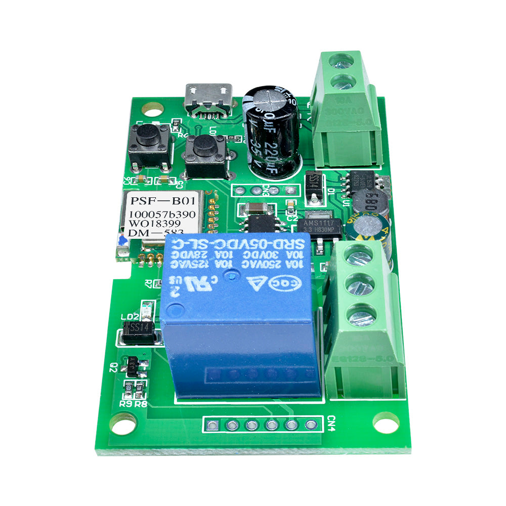
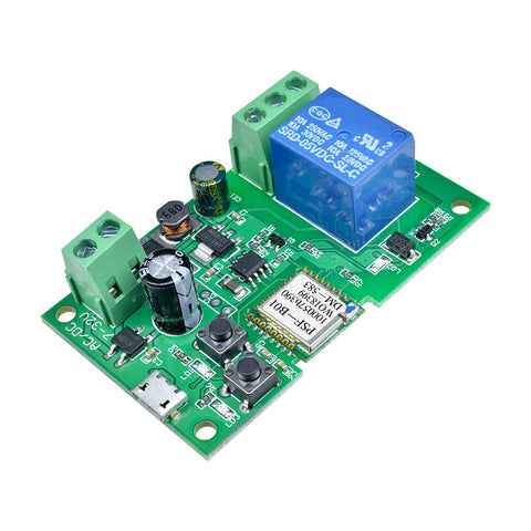 Translation missing: en.products.product.regular_price $8.99{"id":4417209073735,"title":"AC Digital Multifunction Meter Watt Power Volt Amp TTL Current Test Module PZEM 004T With Coil 0 100A 80 260V AC For Arduino","handle":"ac-digital-multifunction-meter-watt-power-volt-amp-ttl-current-test-module-pzem-004t-with-coil-0-100a-80-260v-ac-for-arduino","description":"\u003cdiv\u003e\n\u003cwidget data-widget-type=\"customText\" id=\"23614578\" title=\"011086\" type=\"custom\"\u003e\u003c\/widget\u003e \u003cp\u003e \u003c\/p\u003e \u003cp\u003e \u003c\/p\u003e \u003cp\u003e \u003cimg alt=\"HTB1ZYSui4PI8KJjSspoq6x6MFXaU\" height=\"40\" src=\"https:\/\/ae01.alicdn.com\/kf\/HTB1ZYSui4PI8KJjSspoq6x6MFXaU.jpg\" width=\"950\"\u003e \u003c\/p\u003e \u003cp\u003e \u003c\/p\u003e \u003cdiv\u003e \u003cspan style=\"font-size: 18.0px;\"\u003e\u003cspan style=\"font-family: arial , helvetica , sans-serif;\"\u003e\u003cstrong\u003eModel: PZEM-004T\u003c\/strong\u003e\u003c\/span\u003e\u003c\/span\u003e \u003c\/div\u003e \u003cdiv\u003e \u003c\/div\u003e \u003cdiv\u003e \u003cdiv\u003e \u003cspan style=\"font-size: 18.0px;\"\u003e\u003cspan style=\"font-family: arial , helvetica , sans-serif;\"\u003eOverview\u003c\/span\u003e\u003c\/span\u003e \u003c\/div\u003e \u003cdiv\u003e \u003cspan style=\"font-size: 18.0px;\"\u003e\u003cspan style=\"font-family: arial , helvetica , sans-serif;\"\u003eThis document describes the specification of the PZEM-004T AC communication module,\u003c\/span\u003e\u003c\/span\u003e \u003c\/div\u003e \u003cdiv\u003e \u003cspan style=\"font-size: 18.0px;\"\u003e\u003cspan style=\"font-family: arial , helvetica , sans-serif;\"\u003ethe module is mainly used for measuring AC voltage, current, active power, frequency, power\u003c\/span\u003e\u003c\/span\u003e \u003c\/div\u003e \u003cdiv\u003e \u003cspan style=\"font-size: 18.0px;\"\u003e\u003cspan style=\"font-family: arial , helvetica , sans-serif;\"\u003efactor and active energy, the module is without display function, the data is read through the TTL\u003c\/span\u003e\u003c\/span\u003e \u003c\/div\u003e \u003cdiv\u003e \u003cspan style=\"font-size: 18.0px;\"\u003e\u003cspan style=\"font-family: arial , helvetica , sans-serif;\"\u003einterface.\u003c\/span\u003e\u003c\/span\u003e \u003c\/div\u003e \u003cdiv\u003e \u003cspan style=\"font-size: 18.0px;\"\u003e\u003cspan style=\"font-family: arial , helvetica , sans-serif;\"\u003ePZEM-004T-10A: Measuring Range 10A (Built-in Shunt)\u003c\/span\u003e\u003c\/span\u003e \u003c\/div\u003e \u003cdiv\u003e \u003cspan style=\"font-size: 18.0px;\"\u003e\u003cspan style=\"font-family: arial , helvetica , sans-serif;\"\u003ePZEM-004T-100A: Measuring Range 100A (external transformer)\u003c\/span\u003e\u003c\/span\u003e \u003c\/div\u003e \u003cdiv\u003e \u003cspan style=\"font-size: 18.0px;\"\u003e\u003cspan style=\"font-family: arial , helvetica , sans-serif;\"\u003e1.Function description\u003c\/span\u003e\u003c\/span\u003e \u003c\/div\u003e \u003cdiv\u003e \u003cspan style=\"font-size: 18.0px;\"\u003e\u003cspan style=\"font-family: arial , helvetica , sans-serif;\"\u003e1.1 Voltage\u003c\/span\u003e\u003c\/span\u003e \u003c\/div\u003e \u003cdiv\u003e \u003cspan style=\"font-size: 18.0px;\"\u003e\u003cspan style=\"font-family: arial , helvetica , sans-serif;\"\u003e1.1.1 Measuring range:80~260V\u003c\/span\u003e\u003c\/span\u003e \u003c\/div\u003e \u003cdiv\u003e \u003cspan style=\"font-size: 18.0px;\"\u003e\u003cspan style=\"font-family: arial , helvetica , sans-serif;\"\u003e1.1.2 Resolution: 0.1V\u003c\/span\u003e\u003c\/span\u003e \u003c\/div\u003e \u003cdiv\u003e \u003cspan style=\"font-size: 18.0px;\"\u003e\u003cspan style=\"font-family: arial , helvetica , sans-serif;\"\u003e1.1.3 Measurement accuracy: 0.5%\u003c\/span\u003e\u003c\/span\u003e \u003c\/div\u003e \u003cdiv\u003e \u003cspan style=\"font-size: 18.0px;\"\u003e\u003cspan style=\"font-family: arial , helvetica , sans-serif;\"\u003e1.2 Current\u003c\/span\u003e\u003c\/span\u003e \u003c\/div\u003e \u003cdiv\u003e \u003cspan style=\"font-size: 18.0px;\"\u003e\u003cspan style=\"font-family: arial , helvetica , sans-serif;\"\u003e1.2.1 Measuring range: 0~10A(PZEM-004T-10A); 0~100A(PZEM-004T-100A)\u003c\/span\u003e\u003c\/span\u003e \u003c\/div\u003e \u003cdiv\u003e \u003cspan style=\"font-size: 18.0px;\"\u003e\u003cspan style=\"font-family: arial , helvetica , sans-serif;\"\u003e1.2.2 Starting measure current: 0.01A(PZEM-004T-10A); 0.02A(PZEM-004T-100A)\u003c\/span\u003e\u003c\/span\u003e \u003c\/div\u003e \u003cdiv\u003e \u003cspan style=\"font-size: 18.0px;\"\u003e\u003cspan style=\"font-family: arial , helvetica , sans-serif;\"\u003e1.2.3 Resolution: 0.001A\u003c\/span\u003e\u003c\/span\u003e \u003c\/div\u003e \u003cdiv\u003e \u003cspan style=\"font-size: 18.0px;\"\u003e\u003cspan style=\"font-family: arial , helvetica , sans-serif;\"\u003e1.2.4 Measurement accuracy: 0.5%\u003c\/span\u003e\u003c\/span\u003e \u003c\/div\u003e \u003cdiv\u003e \u003cspan style=\"font-size: 18.0px;\"\u003e\u003cspan style=\"font-family: arial , helvetica , sans-serif;\"\u003e1.3 Active power\u003c\/span\u003e\u003c\/span\u003e \u003c\/div\u003e \u003cdiv\u003e \u003cspan style=\"font-size: 18.0px;\"\u003e\u003cspan style=\"font-family: arial , helvetica , sans-serif;\"\u003e1.3.1 Measuring range: 0~2.3kW(PZEM-004T-10A); 0~23kW(PZEM-004T-100A)\u003c\/span\u003e\u003c\/span\u003e \u003c\/div\u003e \u003cdiv\u003e \u003cspan style=\"font-size: 18.0px;\"\u003e\u003cspan style=\"font-family: arial , helvetica , sans-serif;\"\u003e1.3.2 Starting measure power: 0.4W\u003c\/span\u003e\u003c\/span\u003e \u003c\/div\u003e \u003cdiv\u003e \u003cspan style=\"font-size: 18.0px;\"\u003e\u003cspan style=\"font-family: arial , helvetica , sans-serif;\"\u003e1.3.3 Resolution: 0.1W\u003c\/span\u003e\u003c\/span\u003e \u003c\/div\u003e \u003cdiv\u003e \u003cspan style=\"font-size: 18.0px;\"\u003e\u003cspan style=\"font-family: arial , helvetica , sans-serif;\"\u003e1.3.4 Display format:\u003c\/span\u003e\u003c\/span\u003e \u003c\/div\u003e \u003cdiv\u003e \u003cspan style=\"font-size: 18.0px;\"\u003e\u003cspan style=\"font-family: arial , helvetica , sans-serif;\"\u003e<1000W, it display one decimal, such as: 999.9W\u003c\/span\u003e\u003c\/span\u003e \u003c\/div\u003e \u003cdiv\u003e \u003cspan style=\"font-size: 18.0px;\"\u003e\u003cspan style=\"font-family: arial , helvetica , sans-serif;\"\u003ege1000W, it display only integer, such as: 1000W\u003c\/span\u003e\u003c\/span\u003e \u003c\/div\u003e \u003cdiv\u003e \u003cspan style=\"font-size: 18.0px;\"\u003e\u003cspan style=\"font-family: arial , helvetica , sans-serif;\"\u003e1.3.5 Measurement accuracy: 0.5%\u003c\/span\u003e\u003c\/span\u003e \u003c\/div\u003e \u003cdiv\u003e \u003cspan style=\"font-size: 18.0px;\"\u003e\u003cspan style=\"font-family: arial , helvetica , sans-serif;\"\u003e1.4 Power factor\u003c\/span\u003e\u003c\/span\u003e \u003c\/div\u003e \u003cdiv\u003e \u003cspan style=\"font-size: 18.0px;\"\u003e\u003cspan style=\"font-family: arial , helvetica , sans-serif;\"\u003e1.4.1 Measuring range: 0.00~1.00\u003c\/span\u003e\u003c\/span\u003e \u003c\/div\u003e \u003cdiv\u003e \u003cspan style=\"font-size: 18.0px;\"\u003e\u003cspan style=\"font-family: arial , helvetica , sans-serif;\"\u003e1.4.2 Resolution: 0.01\u003c\/span\u003e\u003c\/span\u003e \u003c\/div\u003e \u003cdiv\u003e \u003cspan style=\"font-size: 18.0px;\"\u003e\u003cspan style=\"font-family: arial , helvetica , sans-serif;\"\u003e1.4.3 Measurement accuracy: 1%\u003c\/span\u003e\u003c\/span\u003e \u003c\/div\u003e \u003cdiv\u003e \u003cspan style=\"font-size: 18.0px;\"\u003e\u003cspan style=\"font-family: arial , helvetica , sans-serif;\"\u003e1.5 Frequency\u003c\/span\u003e\u003c\/span\u003e \u003c\/div\u003e \u003cdiv\u003e \u003cspan style=\"font-size: 18.0px;\"\u003e\u003cspan style=\"font-family: arial , helvetica , sans-serif;\"\u003e1.5.1 Measuring range: 45Hz~65Hz\u003c\/span\u003e\u003c\/span\u003e \u003c\/div\u003e \u003cdiv\u003e \u003cspan style=\"font-size: 18.0px;\"\u003e\u003cspan style=\"font-family: arial , helvetica , sans-serif;\"\u003e1.5.2 Resolution: 0.1Hz\u003c\/span\u003e\u003c\/span\u003e \u003c\/div\u003e \u003cdiv\u003e \u003cspan style=\"font-size: 18.0px;\"\u003e\u003cspan style=\"font-family: arial , helvetica , sans-serif;\"\u003e1.5.3 Measurement accuracy: 0.5%\u003c\/span\u003e\u003c\/span\u003e \u003c\/div\u003e \u003cdiv\u003e \u003cspan style=\"font-size: 18.0px;\"\u003e\u003cspan style=\"font-family: arial , helvetica , sans-serif;\"\u003e1.6 Active energy\u003c\/span\u003e\u003c\/span\u003e \u003c\/div\u003e \u003cdiv\u003e \u003cspan style=\"font-size: 18.0px;\"\u003e\u003cspan style=\"font-family: arial , helvetica , sans-serif;\"\u003e1.6.1 Measuring range: 0~9999.99kWh\u003c\/span\u003e\u003c\/span\u003e \u003c\/div\u003e \u003cdiv\u003e \u003cspan style=\"font-size: 18.0px;\"\u003e\u003cspan style=\"font-family: arial , helvetica , sans-serif;\"\u003e1.6.2 Resolution: 1Wh\u003c\/span\u003e\u003c\/span\u003e \u003c\/div\u003e \u003cdiv\u003e \u003cspan style=\"font-size: 18.0px;\"\u003e\u003cspan style=\"font-family: arial , helvetica , sans-serif;\"\u003e1.6.3 Measurement accuracy: 0.5%\u003c\/span\u003e\u003c\/span\u003e \u003c\/div\u003e \u003cdiv\u003e \u003cspan style=\"font-size: 18.0px;\"\u003e\u003cspan style=\"font-family: arial , helvetica , sans-serif;\"\u003e1.6.4 Display format:\u003c\/span\u003e\u003c\/span\u003e \u003c\/div\u003e \u003cdiv\u003e \u003cspan style=\"font-size: 18.0px;\"\u003e\u003cspan style=\"font-family: arial , helvetica , sans-serif;\"\u003e<10kWh, the display unit is Wh(1kWh=1000Wh), such as: 9999Wh\u003c\/span\u003e\u003c\/span\u003e \u003c\/div\u003e \u003cdiv\u003e \u003cspan style=\"font-size: 18.0px;\"\u003e\u003cspan style=\"font-family: arial , helvetica , sans-serif;\"\u003ege10kWh, the display unit is kWh, such as: 9999.99kWh\u003c\/span\u003e\u003c\/span\u003e \u003c\/div\u003e \u003cdiv\u003e \u003cspan style=\"font-size: 18.0px;\"\u003e\u003cspan style=\"font-family: arial , helvetica , sans-serif;\"\u003e1.6.5 Reset energy: use software to reset.\u003c\/span\u003e\u003c\/span\u003e \u003c\/div\u003e \u003cdiv\u003e \u003cspan style=\"font-size: 18.0px;\"\u003e\u003cspan style=\"font-family: arial , helvetica , sans-serif;\"\u003e1.7 Over power alarm\u003c\/span\u003e\u003c\/span\u003e \u003c\/div\u003e \u003cdiv\u003e \u003cspan style=\"font-size: 18.0px;\"\u003e\u003cspan style=\"font-family: arial , helvetica , sans-serif;\"\u003eActive power threshold can be set, when the measured active power exceeds the threshold, it\u003c\/span\u003e\u003c\/span\u003e \u003c\/div\u003e \u003cdiv\u003e \u003cspan style=\"font-size: 18.0px;\"\u003e\u003cspan style=\"font-family: arial , helvetica , sans-serif;\"\u003ecan alarm\u003c\/span\u003e\u003c\/span\u003e \u003c\/div\u003e \u003cdiv\u003e \u003cspan style=\"font-size: 18.0px;\"\u003e\u003cspan style=\"font-family: arial , helvetica , sans-serif;\"\u003e1.8 Communication interface\u003c\/span\u003e\u003c\/span\u003e \u003c\/div\u003e \u003cdiv\u003e \u003cspan style=\"font-size: 18.0px;\"\u003e\u003cspan style=\"font-family: arial , helvetica , sans-serif;\"\u003eRS485 interface。\u003c\/span\u003e\u003c\/span\u003e \u003c\/div\u003e \u003cdiv\u003e \u003cspan style=\"font-size: 18.0px;\"\u003e\u003cspan style=\"font-family: arial , helvetica , sans-serif;\"\u003e2 Communication protocol\u003c\/span\u003e\u003c\/span\u003e \u003c\/div\u003e \u003cdiv\u003e \u003cspan style=\"font-size: 18.0px;\"\u003e\u003cspan style=\"font-family: arial , helvetica , sans-serif;\"\u003e2.1 Physical layer protocol\u003c\/span\u003e\u003c\/span\u003e \u003c\/div\u003e \u003cdiv\u003e \u003cspan style=\"font-size: 18.0px;\"\u003e\u003cspan style=\"font-family: arial , helvetica , sans-serif;\"\u003ePhysical layer use UART to RS485 communication interface\u003c\/span\u003e\u003c\/span\u003e \u003c\/div\u003e \u003cdiv\u003e \u003cspan style=\"font-size: 18.0px;\"\u003e\u003cspan style=\"font-family: arial , helvetica , sans-serif;\"\u003eBaud rate is 9600, 8 data bits, 1 stop bit, no parity\u003c\/span\u003e\u003c\/span\u003e \u003c\/div\u003e \u003cdiv\u003e \u003cspan style=\"font-size: 18.0px;\"\u003e\u003cspan style=\"font-family: arial , helvetica , sans-serif;\"\u003e2.2 Application layer protocol\u003c\/span\u003e\u003c\/span\u003e \u003c\/div\u003e \u003cdiv\u003e \u003cspan style=\"font-size: 18.0px;\"\u003e\u003cspan style=\"font-family: arial , helvetica , sans-serif;\"\u003eThe application layer use the Modbus-RTU protocol to communicate. At present, it only\u003c\/span\u003e\u003c\/span\u003e \u003c\/div\u003e \u003cdiv\u003e \u003cspan style=\"font-size: 18.0px;\"\u003e\u003cspan style=\"font-family: arial , helvetica , sans-serif;\"\u003esupports function codes such as 0x03 (Read Holding Register), 0x04 (Read Input Register), 0x06\u003c\/span\u003e\u003c\/span\u003e \u003c\/div\u003e \u003cdiv\u003e \u003cspan style=\"font-size: 18.0px;\"\u003e\u003cspan style=\"font-family: arial , helvetica , sans-serif;\"\u003e(Write Single Register), 0x41 (Calibration), 0x42 (Reset energy).etc.\u003c\/span\u003e\u003c\/span\u003e \u003c\/div\u003e \u003cdiv\u003e \u003cspan style=\"font-size: 18.0px;\"\u003e\u003cspan style=\"font-family: arial , helvetica , sans-serif;\"\u003e0x41 function code is only for internal use (address can be only 0xF8), used for factory\u003c\/span\u003e\u003c\/span\u003e \u003c\/div\u003e \u003cdiv\u003e \u003cspan style=\"font-size: 18.0px;\"\u003e\u003cspan style=\"font-family: arial , helvetica , sans-serif;\"\u003ecalibration and return to factory maintenance occasions, after the function code to increase 16-bit\u003c\/span\u003e\u003c\/span\u003e \u003c\/div\u003e \u003cdiv\u003e \u003cspan style=\"font-size: 18.0px;\"\u003e\u003cspan style=\"font-family: arial , helvetica , sans-serif;\"\u003epassword, the default password is 0x3721\u003c\/span\u003e\u003c\/span\u003e \u003c\/div\u003e \u003cdiv\u003e \u003cspan style=\"font-size: 18.0px;\"\u003e\u003cspan style=\"font-family: arial , helvetica , sans-serif;\"\u003eThe address range of the slave is 0x01 ~ 0xF7. The address 0x00 is used as the broadcast\u003c\/span\u003e\u003c\/span\u003e \u003c\/div\u003e \u003cdiv\u003e \u003cspan style=\"font-size: 18.0px;\"\u003e\u003cspan style=\"font-family: arial , helvetica , sans-serif;\"\u003eaddress, the slave does not need to reply the master. The address 0xF8 is used as the general\u003c\/span\u003e\u003c\/span\u003e \u003c\/div\u003e \u003cdiv\u003e \u003cspan style=\"font-size: 18.0px;\"\u003e\u003cspan style=\"font-family: arial , helvetica , sans-serif;\"\u003eaddress, this address can be only used in single-slave environment and can be used for calibration\u003c\/span\u003e\u003c\/span\u003e \u003c\/div\u003e \u003cdiv\u003e \u003cspan style=\"font-size: 18.0px;\"\u003e\u003cspan style=\"font-family: arial , helvetica , sans-serif;\"\u003eetc.operation.\u003c\/span\u003e\u003c\/span\u003e \u003c\/div\u003e \u003cdiv\u003e \u003cspan style=\"font-size: 18.0px;\"\u003e\u003cspan style=\"font-family: arial , helvetica , sans-serif;\"\u003e2.3 Read the measurement result\u003c\/span\u003e\u003c\/span\u003e \u003c\/div\u003e \u003cdiv\u003e \u003cspan style=\"font-size: 18.0px;\"\u003e\u003cspan style=\"font-family: arial , helvetica , sans-serif;\"\u003eThe command format of the master reads the measurement result is(total of 8 bytes):\u003c\/span\u003e\u003c\/span\u003e \u003c\/div\u003e \u003cdiv\u003e \u003cspan style=\"font-size: 18.0px;\"\u003e\u003cspan style=\"font-family: arial , helvetica , sans-serif;\"\u003eSlave Address + 0x04 + Register Address High Byte + Register Address Low Byte + Number\u003c\/span\u003e\u003c\/span\u003e \u003c\/div\u003e \u003cdiv\u003e \u003cspan style=\"font-size: 18.0px;\"\u003e\u003cspan style=\"font-family: arial , helvetica , sans-serif;\"\u003eof Registers High Byte + Number of Registers Low Byte + CRC Check High Byte + CRC Check\u003c\/span\u003e\u003c\/span\u003e \u003c\/div\u003e \u003cdiv\u003e \u003cspan style=\"font-size: 18.0px;\"\u003e\u003cspan style=\"font-family: arial , helvetica , sans-serif;\"\u003eLow Byte.\u003c\/span\u003e\u003c\/span\u003e \u003c\/div\u003e \u003cdiv\u003e \u003cspan style=\"font-size: 18.0px;\"\u003e\u003cspan style=\"font-family: arial , helvetica , sans-serif;\"\u003eThe command format of the reply from the slave is divided into two kinds:\u003c\/span\u003e\u003c\/span\u003e \u003c\/div\u003e \u003cdiv\u003e \u003cspan style=\"font-size: 18.0px;\"\u003e\u003cspan style=\"font-family: arial , helvetica , sans-serif;\"\u003eCorrect Reply: Slave Address + 0x04 + Number of Bytes + Register 1 Data High Byte +\u003c\/span\u003e\u003c\/span\u003e \u003c\/div\u003e \u003cdiv\u003e \u003cspan style=\"font-size: 18.0px;\"\u003e\u003cspan style=\"font-family: arial , helvetica , sans-serif;\"\u003eRegister 1 Data Low Byte + ... + CRC Check High Byte + CRC Check Low Byte\u003c\/span\u003e\u003c\/span\u003e \u003c\/div\u003e \u003cdiv\u003e \u003cspan style=\"font-size: 18.0px;\"\u003e\u003cspan style=\"font-family: arial , helvetica , sans-serif;\"\u003eError Reply: Slave address + 0x84 + Abnormal code + CRC check high byte + CRC check\u003c\/span\u003e\u003c\/span\u003e \u003c\/div\u003e \u003cdiv\u003e \u003cspan style=\"font-size: 18.0px;\"\u003e\u003cspan style=\"font-family: arial , helvetica , sans-serif;\"\u003elow byte\u003c\/span\u003e\u003c\/span\u003e \u003c\/div\u003e \u003cdiv\u003e \u003cspan style=\"font-size: 18.0px;\"\u003e\u003cspan style=\"font-family: arial , helvetica , sans-serif;\"\u003eAbnormal code analyzed as following (the same below)\u003c\/span\u003e\u003c\/span\u003e \u003c\/div\u003e \u003cdiv\u003e \u003cspan style=\"font-size: 18.0px;\"\u003e\u003cspan style=\"font-family: arial , helvetica , sans-serif;\"\u003e⚫ 0x01,Illegal function\u003c\/span\u003e\u003c\/span\u003e \u003c\/div\u003e \u003cdiv\u003e \u003cspan style=\"font-size: 18.0px;\"\u003e\u003cspan style=\"font-family: arial , helvetica , sans-serif;\"\u003e⚫ 0x02,Illegal address\u003c\/span\u003e\u003c\/span\u003e \u003c\/div\u003e \u003cdiv\u003e \u003cspan style=\"font-size: 18.0px;\"\u003e\u003cspan style=\"font-family: arial , helvetica , sans-serif;\"\u003e⚫ 0x03,Illegal data\u003c\/span\u003e\u003c\/span\u003e \u003c\/div\u003e \u003c\/div\u003e \u003cdiv\u003e \u003cspan style=\"font-family: arial , helvetica , sans-serif;font-size: 18.0px;\"\u003e⚫ 0x04,Slave error\u003c\/span\u003e \u003cspan style=\"font-family: arial , helvetica , sans-serif;font-size: 18.0px;\"\u003e \u003c\/span\u003e \u003c\/div\u003e \u003cdiv\u003e \u003cspan style=\"font-family: arial , helvetica , sans-serif;font-size: 18.0px;\"\u003e\u003cimg alt=\"1\" src=\"https:\/\/ae01.alicdn.com\/kf\/HTB1hnE1RzTpK1RjSZKPq6y3UpXaT.jpg\"\u003e\u003c\/span\u003e \u003c\/div\u003e \u003cdiv\u003e \u003c\/div\u003e \u003cdiv\u003e \u003cspan style=\"font-family: arial , helvetica , sans-serif;font-size: 18.0px;\"\u003eFor example, the master sends the following command (CRC check code is replaced by\u003c\/span\u003e \u003c\/div\u003e \u003cdiv\u003e \u003cspan style=\"font-size: 18.0px;\"\u003e\u003cspan style=\"font-family: arial , helvetica , sans-serif;\"\u003e0xHH and 0xLL, the same below)\u003c\/span\u003e\u003c\/span\u003e \u003c\/div\u003e \u003cdiv\u003e \u003cspan style=\"font-size: 18.0px;\"\u003e\u003cspan style=\"font-family: arial , helvetica , sans-serif;\"\u003e0x01 + 0x04 + 0x00 + 0x00 + 0x00 + 0x0A + 0xHH + 0xLL\u003c\/span\u003e\u003c\/span\u003e \u003c\/div\u003e \u003cdiv\u003e \u003cspan style=\"font-size: 18.0px;\"\u003e\u003cspan style=\"font-family: arial , helvetica , sans-serif;\"\u003eIndicates that the master needs to read 10 registers with slave address 0x01 and the start\u003c\/span\u003e\u003c\/span\u003e \u003c\/div\u003e \u003cdiv\u003e \u003cspan style=\"font-size: 18.0px;\"\u003e\u003cspan style=\"font-family: arial , helvetica , sans-serif;\"\u003eaddress of the register is 0x0000\u003c\/span\u003e\u003c\/span\u003e \u003c\/div\u003e \u003cdiv\u003e \u003cspan style=\"font-size: 18.0px;\"\u003e\u003cspan style=\"font-family: arial , helvetica , sans-serif;\"\u003eThe correct reply from the slave is as following:\u003c\/span\u003e\u003c\/span\u003e \u003c\/div\u003e \u003cdiv\u003e \u003cspan style=\"font-size: 18.0px;\"\u003e\u003cspan style=\"font-family: arial , helvetica , sans-serif;\"\u003e0x01 + 0x04 + 0x14 + 0x08 + 0x98 + 0x03 + 0xE8+0x00 + 0x00 +0x08 + 0x98+ 0x00 +\u003c\/span\u003e\u003c\/span\u003e \u003c\/div\u003e \u003cdiv\u003e \u003cspan style=\"font-size: 18.0px;\"\u003e\u003cspan style=\"font-family: arial , helvetica , sans-serif;\"\u003e0x00 + 0x00 + 0x00 + 0x00 + 0x00 + 0x01 + 0xF4 + 0x00 + 0x64 + 0x00 + 0x00 + 0xHH + 0xLL\u003c\/span\u003e\u003c\/span\u003e \u003c\/div\u003e \u003cdiv\u003e \u003cspan style=\"font-size: 18.0px;\"\u003e\u003cspan style=\"font-family: arial , helvetica , sans-serif;\"\u003eThe above data shows\u003c\/span\u003e\u003c\/span\u003e \u003c\/div\u003e \u003cdiv\u003e \u003cspan style=\"font-size: 18.0px;\"\u003e\u003cspan style=\"font-family: arial , helvetica , sans-serif;\"\u003e⚫ Voltage is 0x0898, converted to decimal is 2200, display 220.0V\u003c\/span\u003e\u003c\/span\u003e \u003c\/div\u003e \u003cdiv\u003e \u003cspan style=\"font-size: 18.0px;\"\u003e\u003cspan style=\"font-family: arial , helvetica , sans-serif;\"\u003e⚫ Current is 0x000003E8, converted to decimal is 1000, display 1.000A\u003c\/span\u003e\u003c\/span\u003e \u003c\/div\u003e \u003cdiv\u003e \u003cspan style=\"font-size: 18.0px;\"\u003e\u003cspan style=\"font-family: arial , helvetica , sans-serif;\"\u003e⚫ Power is 0x00000898, converted to decimal is 2200, display 220.0W\u003c\/span\u003e\u003c\/span\u003e \u003c\/div\u003e \u003cdiv\u003e \u003cspan style=\"font-size: 18.0px;\"\u003e\u003cspan style=\"font-family: arial , helvetica , sans-serif;\"\u003e⚫ Energy is 0x00000000, converted to decimal is 0, display 0Wh\u003c\/span\u003e\u003c\/span\u003e \u003c\/div\u003e \u003cdiv\u003e \u003cspan style=\"font-size: 18.0px;\"\u003e\u003cspan style=\"font-family: arial , helvetica , sans-serif;\"\u003e⚫ Frequency is 0x01F4, converted to decimal is 500, display 50.0Hz\u003c\/span\u003e\u003c\/span\u003e \u003c\/div\u003e \u003cdiv\u003e \u003cspan style=\"font-size: 18.0px;\"\u003e\u003cspan style=\"font-family: arial , helvetica , sans-serif;\"\u003e⚫ Power factor is 0x0064, converted to decimal is 100, display 1.00\u003c\/span\u003e\u003c\/span\u003e \u003c\/div\u003e \u003cdiv\u003e \u003cspan style=\"font-size: 18.0px;\"\u003e\u003cspan style=\"font-family: arial , helvetica , sans-serif;\"\u003e⚫ Alarm status is 0x0000, indicates that the current power is lower than the alarm power\u003c\/span\u003e\u003c\/span\u003e \u003c\/div\u003e \u003cdiv\u003e \u003cspan style=\"font-size: 18.0px;\"\u003e\u003cspan style=\"font-family: arial , helvetica , sans-serif;\"\u003ethreshold\u003c\/span\u003e\u003c\/span\u003e \u003c\/div\u003e \u003cdiv\u003e \u003cspan style=\"font-size: 18.0px;\"\u003e\u003cspan style=\"font-family: arial , helvetica , sans-serif;\"\u003e2.4 Read and modify the slave parameters\u003c\/span\u003e\u003c\/span\u003e \u003c\/div\u003e \u003cdiv\u003e \u003cspan style=\"font-size: 18.0px;\"\u003e\u003cspan style=\"font-family: arial , helvetica , sans-serif;\"\u003eAt present,it only supports reading and modifying slave address and power alarm threshold\u003c\/span\u003e\u003c\/span\u003e \u003c\/div\u003e \u003cdiv\u003e \u003cspan style=\"font-size: 18.0px;\"\u003e\u003cspan style=\"font-family: arial , helvetica , sans-serif;\"\u003eThe register is arranged as the following table\u003c\/span\u003e\u003c\/span\u003e \u003c\/div\u003e \u003cdiv\u003e \u003cspan style=\"font-size: 18.0px;\"\u003e\u003cspan style=\"font-family: arial , helvetica , sans-serif;\"\u003e\u003cimg alt=\"2\" src=\"https:\/\/ae01.alicdn.com\/kf\/HTB1QmhWeK3tHKVjSZSgq6x4QFXa5.jpg\"\u003e\u003c\/span\u003e\u003c\/span\u003e \u003c\/div\u003e \u003cdiv\u003e \u003c\/div\u003e \u003cdiv\u003e \u003cspan style=\"font-family: arial , helvetica , sans-serif;font-size: 18.0px;\"\u003eThe command format of the master to read the slave parameters and read the measurement\u003c\/span\u003e \u003c\/div\u003e \u003cdiv\u003e \u003cspan style=\"font-size: 18.0px;\"\u003e\u003cspan style=\"font-family: arial , helvetica , sans-serif;\"\u003eresults are same(descrybed in details in Section 2.3), only need to change the function code from\u003c\/span\u003e\u003c\/span\u003e \u003c\/div\u003e \u003cdiv\u003e \u003cspan style=\"font-size: 18.0px;\"\u003e\u003cspan style=\"font-family: arial , helvetica , sans-serif;\"\u003e0x04 to 0x03.\u003c\/span\u003e\u003c\/span\u003e \u003c\/div\u003e \u003cdiv\u003e \u003cspan style=\"font-size: 18.0px;\"\u003e\u003cspan style=\"font-family: arial , helvetica , sans-serif;\"\u003eThe command format of the master to modify the slave parameters is (total of 8 bytes):\u003c\/span\u003e\u003c\/span\u003e \u003c\/div\u003e \u003cdiv\u003e \u003cspan style=\"font-size: 18.0px;\"\u003e\u003cspan style=\"font-family: arial , helvetica , sans-serif;\"\u003eSlave Address + 0x06 + Register Address High Byte + Register Address Low Byte + Register\u003c\/span\u003e\u003c\/span\u003e \u003c\/div\u003e \u003cdiv\u003e \u003cspan style=\"font-size: 18.0px;\"\u003e\u003cspan style=\"font-family: arial , helvetica , sans-serif;\"\u003eValue High Byte + Register Value Low Byte + CRC Check High Byte + CRC Check Low Byte.\u003c\/span\u003e\u003c\/span\u003e \u003c\/div\u003e \u003cdiv\u003e \u003cspan style=\"font-size: 18.0px;\"\u003e\u003cspan style=\"font-family: arial , helvetica , sans-serif;\"\u003eThe command format of the reply from the slave is divided into two kinds:\u003c\/span\u003e\u003c\/span\u003e \u003c\/div\u003e \u003cdiv\u003e \u003cspan style=\"font-size: 18.0px;\"\u003e\u003cspan style=\"font-family: arial , helvetica , sans-serif;\"\u003eCorrect Response: Slave Address + 0x06 + Number of Bytes + Register Address Low Byte +\u003c\/span\u003e\u003c\/span\u003e \u003c\/div\u003e \u003cdiv\u003e \u003cspan style=\"font-size: 18.0px;\"\u003e\u003cspan style=\"font-family: arial , helvetica , sans-serif;\"\u003eRegister Value High Byte + Register Value Low Byte + CRC Check High Byte + CRC Check Low\u003c\/span\u003e\u003c\/span\u003e \u003c\/div\u003e \u003cdiv\u003e \u003cspan style=\"font-size: 18.0px;\"\u003e\u003cspan style=\"font-family: arial , helvetica , sans-serif;\"\u003eByte.\u003c\/span\u003e\u003c\/span\u003e \u003c\/div\u003e \u003cdiv\u003e \u003cspan style=\"font-size: 18.0px;\"\u003e\u003cspan style=\"font-family: arial , helvetica , sans-serif;\"\u003eError Reply: Slave address + 0x86 + Abnormal code + CRC check high byte + CRC check\u003c\/span\u003e\u003c\/span\u003e \u003c\/div\u003e \u003cdiv\u003e \u003cspan style=\"font-size: 18.0px;\"\u003e\u003cspan style=\"font-family: arial , helvetica , sans-serif;\"\u003elow byte.\u003c\/span\u003e\u003c\/span\u003e \u003c\/div\u003e \u003cdiv\u003e \u003cspan style=\"font-size: 18.0px;\"\u003e\u003cspan style=\"font-family: arial , helvetica , sans-serif;\"\u003eFor example, the master sets the slave's power alarm threshold:\u003c\/span\u003e\u003c\/span\u003e \u003c\/div\u003e \u003cdiv\u003e \u003cspan style=\"font-size: 18.0px;\"\u003e\u003cspan style=\"font-family: arial , helvetica , sans-serif;\"\u003e0x01 + 0x06 + 0x00 + 0x01 + 0x08 + 0xFC + 0xHH + 0xLL\u003c\/span\u003e\u003c\/span\u003e \u003c\/div\u003e \u003cdiv\u003e \u003cspan style=\"font-size: 18.0px;\"\u003e\u003cspan style=\"font-family: arial , helvetica , sans-serif;\"\u003eIndicates that the master needs to set the 0x0001 register (power alarm threshold) to 0x08FC\u003c\/span\u003e\u003c\/span\u003e \u003c\/div\u003e \u003cdiv\u003e \u003cspan style=\"font-size: 18.0px;\"\u003e\u003cspan style=\"font-family: arial , helvetica , sans-serif;\"\u003e(2300W).\u003c\/span\u003e\u003c\/span\u003e \u003c\/div\u003e \u003cdiv\u003e \u003cspan style=\"font-size: 18.0px;\"\u003e\u003cspan style=\"font-family: arial , helvetica , sans-serif;\"\u003eSet up correctly, the slave return to the data which is sent from the master.\u003c\/span\u003e\u003c\/span\u003e \u003c\/div\u003e \u003cdiv\u003e \u003cspan style=\"font-size: 18.0px;\"\u003e\u003cspan style=\"font-family: arial , helvetica , sans-serif;\"\u003eFor example, the master sets the address of the slave\u003c\/span\u003e\u003c\/span\u003e \u003c\/div\u003e \u003cdiv\u003e \u003cspan style=\"font-size: 18.0px;\"\u003e\u003cspan style=\"font-family: arial , helvetica , sans-serif;\"\u003e0x01 + 0x06 + 0x00 + 0x02 + 0x00 + 0x05 + 0xHH + 0xLL\u003c\/span\u003e\u003c\/span\u003e \u003c\/div\u003e \u003cdiv\u003e \u003cspan style=\"font-size: 18.0px;\"\u003e\u003cspan style=\"font-family: arial , helvetica , sans-serif;\"\u003eIndicates that the master needs to set the 0x0002 register (Modbus-RTU address) to 0x0005\u003c\/span\u003e\u003c\/span\u003e \u003c\/div\u003e \u003cdiv\u003e \u003cspan style=\"font-size: 18.0px;\"\u003e\u003cspan style=\"font-family: arial , helvetica , sans-serif;\"\u003eSet up correctly, the slave return to the data which is sent from the master.\u003c\/span\u003e\u003c\/span\u003e \u003c\/div\u003e \u003cdiv\u003e \u003cspan style=\"font-size: 18.0px;\"\u003e\u003cspan style=\"font-family: arial , helvetica , sans-serif;\"\u003e2.5 Reset energy\u003c\/span\u003e\u003c\/span\u003e \u003c\/div\u003e \u003cdiv\u003e \u003cspan style=\"font-size: 18.0px;\"\u003e\u003cspan style=\"font-family: arial , helvetica , sans-serif;\"\u003eThe command format of the master to reset the slave's energy is (total 4 bytes):\u003c\/span\u003e\u003c\/span\u003e \u003c\/div\u003e \u003cdiv\u003e \u003cspan style=\"font-size: 18.0px;\"\u003e\u003cspan style=\"font-family: arial , helvetica , sans-serif;\"\u003eSlave address + 0x42 + CRC check high byte + CRC check low byte.\u003c\/span\u003e\u003c\/span\u003e \u003c\/div\u003e \u003cdiv\u003e \u003cspan style=\"font-size: 18.0px;\"\u003e\u003cspan style=\"font-family: arial , helvetica , sans-serif;\"\u003eCorrect reply: slave address + 0x42 + CRC check high byte + CRC check low byte.\u003c\/span\u003e\u003c\/span\u003e \u003c\/div\u003e \u003cdiv\u003e \u003cspan style=\"font-size: 18.0px;\"\u003e\u003cspan style=\"font-family: arial , helvetica , sans-serif;\"\u003eError Reply: Slave address + 0xC2 + Abnormal code + CRC check high byte + CRC check\u003c\/span\u003e\u003c\/span\u003e \u003c\/div\u003e \u003cdiv\u003e \u003cspan style=\"font-size: 18.0px;\"\u003e\u003cspan style=\"font-family: arial , helvetica , sans-serif;\"\u003elow byte\u003c\/span\u003e\u003c\/span\u003e \u003c\/div\u003e \u003cdiv\u003e \u003cspan style=\"font-size: 18.0px;\"\u003e\u003cspan style=\"font-family: arial , helvetica , sans-serif;\"\u003e2.6 Calibration\u003c\/span\u003e\u003c\/span\u003e \u003c\/div\u003e \u003cdiv\u003e \u003cspan style=\"font-size: 18.0px;\"\u003e\u003cspan style=\"font-family: arial , helvetica , sans-serif;\"\u003eThe command format of the master to calibrate the slave is (total 6 bytes):\u003c\/span\u003e\u003c\/span\u003e \u003c\/div\u003e \u003cdiv\u003e \u003cspan style=\"font-size: 18.0px;\"\u003e\u003cspan style=\"font-family: arial , helvetica , sans-serif;\"\u003e0xF8 + 0x41 + 0x37 + 0x21 + CRC check high byte + CRC check low byte.\u003c\/span\u003e\u003c\/span\u003e \u003c\/div\u003e \u003cdiv\u003e \u003cspan style=\"font-size: 18.0px;\"\u003e\u003cspan style=\"font-family: arial , helvetica , sans-serif;\"\u003eCorrect reply: 0xF8 + 0x41 + 0x37 + 0x21 + CRC check high byte + CRC check low byte.\u003c\/span\u003e\u003c\/span\u003e \u003c\/div\u003e \u003cdiv\u003e \u003cspan style=\"font-size: 18.0px;\"\u003e\u003cspan style=\"font-family: arial , helvetica , sans-serif;\"\u003eError Reply: 0xF8 + 0xC1 + Abnormal code + CRC check high byte + CRC check low byte.\u003c\/span\u003e\u003c\/span\u003e \u003c\/div\u003e \u003cdiv\u003e \u003cspan style=\"font-size: 18.0px;\"\u003e\u003cspan style=\"font-family: arial , helvetica , sans-serif;\"\u003eIt should be noted that the calibration takes 3 to 4 seconds, after the master sends the\u003c\/span\u003e\u003c\/span\u003e \u003c\/div\u003e \u003cdiv\u003e \u003cspan style=\"font-size: 18.0px;\"\u003e\u003cspan style=\"font-family: arial , helvetica , sans-serif;\"\u003ecommand, if the calibration is successful, it will take 3 ~ 4 seconds to receive the response from\u003c\/span\u003e\u003c\/span\u003e \u003c\/div\u003e \u003cdiv\u003e \u003cspan style=\"font-size: 18.0px;\"\u003e\u003cspan style=\"font-family: arial , helvetica , sans-serif;\"\u003ethe slave.\u003c\/span\u003e\u003c\/span\u003e \u003c\/div\u003e \u003cdiv\u003e \u003cspan style=\"font-size: 18.0px;\"\u003e\u003cspan style=\"font-family: arial , helvetica , sans-serif;\"\u003e2.7 CRC check\u003c\/span\u003e\u003c\/span\u003e \u003c\/div\u003e \u003cdiv\u003e \u003cspan style=\"font-size: 18.0px;\"\u003e\u003cspan style=\"font-family: arial , helvetica , sans-serif;\"\u003eCRC check use 16bits format, occupy two bytes, the generator polynomial is X16 + X15 +\u003c\/span\u003e\u003c\/span\u003e \u003c\/div\u003e \u003cdiv\u003e \u003cspan style=\"font-size: 18.0px;\"\u003e\u003cspan style=\"font-family: arial , helvetica , sans-serif;\"\u003eX2 +1, the polynomial value used for calculation is 0xA001.\u003c\/span\u003e\u003c\/span\u003e \u003c\/div\u003e \u003cdiv\u003e \u003cspan style=\"font-size: 18.0px;\"\u003e\u003cspan style=\"font-family: arial , helvetica , sans-serif;\"\u003eThe value of the CRC check is a frame data divide all results of checking all the bytes except\u003c\/span\u003e\u003c\/span\u003e \u003c\/div\u003e \u003cdiv\u003e \u003cspan style=\"font-size: 18.0px;\"\u003e\u003cspan style=\"font-family: arial , helvetica , sans-serif;\"\u003ethe CRC check value.\u003c\/span\u003e\u003c\/span\u003e \u003c\/div\u003e \u003cdiv\u003e \u003cspan style=\"font-size: 18.0px;\"\u003e\u003cspan style=\"font-family: arial , helvetica , sans-serif;\"\u003e3 Functional block diagram\u003c\/span\u003e\u003c\/span\u003e \u003c\/div\u003e \u003cdiv\u003e \u003cspan style=\"font-size: 18.0px;\"\u003e\u003cspan style=\"font-family: arial , helvetica , sans-serif;\"\u003e\u003cimg alt=\"33\" src=\"https:\/\/ae01.alicdn.com\/kf\/HTB1hYMZRrvpK1RjSZFqq6AXUVXap.jpg\"\u003e\u003cimg alt=\"44\" src=\"https:\/\/ae01.alicdn.com\/kf\/HTB1Z_oZRAvoK1RjSZFDq6xY3pXaH.jpg\"\u003e\u003cimg alt=\"55\" src=\"https:\/\/ae01.alicdn.com\/kf\/HTB1WlsVRr2pK1RjSZFsq6yNlXXaH.jpg\"\u003e\u003cimg alt=\"66\" src=\"https:\/\/ae01.alicdn.com\/kf\/HTB1_No5RpzqK1RjSZFvq6AB7VXaA.jpg\"\u003e\u003c\/span\u003e\u003c\/span\u003e \u003c\/div\u003e \u003cdiv\u003e \u003c\/div\u003e \u003cdiv\u003e \u003cspan style=\"font-family: arial , helvetica , sans-serif;font-size: 18.0px;\"\u003e5 Other instructi5.1The TTL interface ohich means, when come it cannot communica5.2 Working temper-20rsquoC ~ +60rsquoC。\u003c\/span\u003e \u003c\/div\u003e \u003cdiv\u003e \u003c\/div\u003e \u003cdiv\u003e \u003c\/div\u003e \u003cdiv\u003e \u003cspan style=\"font-size: 18.0px;\"\u003e\u003cspan style=\"font-family: arial , helvetica , sans-serif;\"\u003ePackage include:\u003c\/span\u003e\u003c\/span\u003e \u003c\/div\u003e \u003cdiv\u003e \u003c\/div\u003e \u003cdiv\u003e \u003c\/div\u003e \u003cdiv\u003e \u003cspan style=\"font-size: 18.0px;\"\u003e\u003cspan style=\"font-family: arial , helvetica , sans-serif;\"\u003e1x Digital Multi-function Meter\u003c\/span\u003e\u003c\/span\u003e \u003c\/div\u003e \u003cdiv\u003e \u003cspan style=\"font-size: 18.0px;\"\u003e\u003cspan style=\"font-family: arial , helvetica , sans-serif;\"\u003e1x Coil\u003c\/span\u003e\u003c\/span\u003e \u003c\/div\u003e \u003cdiv\u003e \u003c\/div\u003e \u003cdiv\u003e \u003c\/div\u003e \u003cdiv\u003e \u003cimg alt=\"HTB1jCuMiY_I8KJjy1Xaq6zsxpXaS\" height=\"40\" src=\"https:\/\/ae01.alicdn.com\/kf\/HTB1jCuMiY_I8KJjy1Xaq6zsxpXaS.jpg\" width=\"950\"\u003e \u003c\/div\u003e \u003cdiv\u003e \u003c\/div\u003e \u003cdiv\u003e \u003c\/div\u003e \u003cdiv\u003e \u003cimg alt=\"[011446 (1)\" src=\"https:\/\/ae01.alicdn.com\/kf\/HTB1mOfRc21H3KVjSZFHq6zKppXaI.jpg\"\u003e\u003cimg alt=\"[011446 (2)\" src=\"https:\/\/ae01.alicdn.com\/kf\/HTB1JB6Rc21H3KVjSZFBq6zSMXXa6.jpg\"\u003e\u003cimg alt=\"[011446 (3)\" src=\"https:\/\/ae01.alicdn.com\/kf\/HTB1Gm6Uc.uF3KVjSZK9q6zVtXXaF.jpg\"\u003e\u003cimg alt=\"[011446 (6)\" src=\"https:\/\/ae01.alicdn.com\/kf\/HTB1mqvSc2WG3KVjSZFgq6zTspXa9.jpg\"\u003e\u003cimg alt=\"[011446 (7)\" src=\"https:\/\/ae01.alicdn.com\/kf\/HTB1nLfVc8GE3KVjSZFhq6AkaFXa2.jpg\"\u003e\u003cimg alt=\"[011446 (8)\" src=\"https:\/\/ae01.alicdn.com\/kf\/HTB1h4r1c8Kw3KVjSZTEq6AuRpXae.jpg\"\u003e\u003cimg alt=\"[011446 (9)\" src=\"https:\/\/ae01.alicdn.com\/kf\/HTB1nA6Sc.WF3KVjSZPhq6xclXXaa.jpg\"\u003e\u003cimg alt=\"[011446 (10)\" src=\"https:\/\/ae01.alicdn.com\/kf\/HTB1YNjSc.KF3KVjSZFEq6xExFXaq.jpg\"\u003e \u003c\/div\u003e \u003cdiv\u003e \u003c\/div\u003e \u003cdiv\u003e \u003c\/div\u003e \u003cdiv\u003e \u003c\/div\u003e \u003cdiv\u003e \u003cimg alt=\"HTB1CoFQi_TI8KJjSsphq6AFppXax\" height=\"40\" src=\"https:\/\/ae01.alicdn.com\/kf\/HTB1CoFQi_TI8KJjSsphq6AFppXax.jpg\" width=\"950\"\u003e \u003c\/div\u003e \u003cdiv\u003e \u003c\/div\u003e \u003cdiv\u003e \u003c\/div\u003e \u003cdiv\u003e \u003cspan style=\"font-size: 18.0px;\"\u003e\u003cspan style=\"font-family: arial , helvetica , sans-serif;\"\u003e\u003cwidget data-widget-type=\"customText\" id=\"22506092\" title=\"catalogue\" type=\"custom\"\u003e\u003c\/widget\u003e\u003c\/span\u003e\u003c\/span\u003e \u003c\/div\u003e \u003cdiv\u003e \u003c\/div\u003e \u003cdiv\u003e \u003c\/div\u003e \u003cdiv\u003e \u003c\/div\u003e \u003cdiv\u003e \u003c\/div\u003e \u003cp style=\"overflow: hidden;height: 1.0px;padding-bottom: 0.0px;padding-top: 0.0px;padding-left: 0.0px;margin: 0.0px;padding-right: 0.0px;\"\u003e \u003c\/p\u003e \u003cdiv style=\"font-size: 24.0px;font-weight: 600;color: #ff0000;padding-bottom: 8.0px;text-align: center;padding-top: 8.0px;padding-left: 8.0px;padding-right: 8.0px;\"\u003e \u003cimg alt=\"HTB1hs.8XfvsK1RjSspdq6AZepXaz\" height=\"1600\" src=\"https:\/\/ae01.alicdn.com\/kf\/HTB1hs.8XfvsK1RjSspdq6AZepXaz.jpg\" width=\"960\"\u003e \u003c\/div\u003e \u003cscript\u003ewindow.adminAccountId=201164481;\u003c\/script\u003e \u003c\/div\u003e","published_at":"2019-12-23T15:11:26+08:00","created_at":"2019-12-23T15:11:39+08:00","vendor":"diymore","type":"GPS\/GPRS Module","tags":[],"price":999,"price_min":999,"price_max":999,"available":true,"price_varies":false,"compare_at_price":null,"compare_at_price_min":0,"compare_at_price_max":0,"compare_at_price_varies":false,"variants":[{"id":31566818148423,"title":"Default Title","option1":"Default Title","option2":null,"option3":null,"sku":"011446","requires_shipping":true,"taxable":false,"featured_image":null,"available":true,"name":"AC Digital Multifunction Meter Watt Power Volt Amp TTL Current Test Module PZEM 004T With Coil 0 100A 80 260V AC For Arduino","public_title":null,"options":["Default Title"],"price":999,"weight":0,"compare_at_price":null,"inventory_management":"shopify","barcode":"","requires_selling_plan":false,"selling_plan_allocations":[],"quantity_rule":{"min":1,"max":null,"increment":1}}],"images":["\/\/www.diymore.cc\/cdn\/shop\/products\/AC-Digital-Multifunction-Meter-Watt-Power-Volt-Amp-TTL-Current-Test-Module-PZEM-004T-With-Coil_851.jpg?v=1588696534","\/\/www.diymore.cc\/cdn\/shop\/products\/AC-Digital-Multifunction-Meter-Watt-Power-Volt-Amp-TTL-Current-Test-Module-PZEM-004T-With-Coil_b4b588d7-f687-4114-be73-503570c06a07_421.jpg?v=1588696534","\/\/www.diymore.cc\/cdn\/shop\/products\/AC-Digital-Multifunction-Meter-Watt-Power-Volt-Amp-TTL-Current-Test-Module-PZEM-004T-With-Coil_239023ee-d161-478e-a487-655519a1f7c9_794.jpg?v=1588696534","\/\/www.diymore.cc\/cdn\/shop\/products\/AC-Digital-Multifunction-Meter-Watt-Power-Volt-Amp-TTL-Current-Test-Module-PZEM-004T-With-Coil_8ab8cbac-3d82-4519-9119-c8aa2fbfb987_307.jpg?v=1588696534","\/\/www.diymore.cc\/cdn\/shop\/products\/AC-Digital-Multifunction-Meter-Watt-Power-Volt-Amp-TTL-Current-Test-Module-PZEM-004T-With-Coil_4b1e267e-fe03-4c68-89ee-8edf13f26f28_642.jpg?v=1588696534","\/\/www.diymore.cc\/cdn\/shop\/products\/AC-Digital-Multifunction-Meter-Watt-Power-Volt-Amp-TTL-Current-Test-Module-PZEM-004T-With-Coil_e3bbf7bf-2c49-474b-b5de-f0b238a2c00e_491.jpg?v=1588696534"],"featured_image":"\/\/www.diymore.cc\/cdn\/shop\/products\/AC-Digital-Multifunction-Meter-Watt-Power-Volt-Amp-TTL-Current-Test-Module-PZEM-004T-With-Coil_851.jpg?v=1588696534","options":["Title"],"media":[{"alt":"Ac Digital Multifunction Meter Watt Power Volt Amp Ttl Current Test Module Pzem 004T With Coil 0","id":6682211123271,"position":1,"preview_image":{"aspect_ratio":1.0,"height":1000,"width":1000,"src":"\/\/www.diymore.cc\/cdn\/shop\/products\/AC-Digital-Multifunction-Meter-Watt-Power-Volt-Amp-TTL-Current-Test-Module-PZEM-004T-With-Coil_851.jpg?v=1588696534"},"aspect_ratio":1.0,"height":1000,"media_type":"image","src":"\/\/www.diymore.cc\/cdn\/shop\/products\/AC-Digital-Multifunction-Meter-Watt-Power-Volt-Amp-TTL-Current-Test-Module-PZEM-004T-With-Coil_851.jpg?v=1588696534","width":1000},{"alt":"Ac Digital Multifunction Meter Watt Power Volt Amp Ttl Current Test Module Pzem 004T With Coil 0","id":6682211352647,"position":2,"preview_image":{"aspect_ratio":1.0,"height":1000,"width":1000,"src":"\/\/www.diymore.cc\/cdn\/shop\/products\/AC-Digital-Multifunction-Meter-Watt-Power-Volt-Amp-TTL-Current-Test-Module-PZEM-004T-With-Coil_b4b588d7-f687-4114-be73-503570c06a07_421.jpg?v=1588696534"},"aspect_ratio":1.0,"height":1000,"media_type":"image","src":"\/\/www.diymore.cc\/cdn\/shop\/products\/AC-Digital-Multifunction-Meter-Watt-Power-Volt-Amp-TTL-Current-Test-Module-PZEM-004T-With-Coil_b4b588d7-f687-4114-be73-503570c06a07_421.jpg?v=1588696534","width":1000},{"alt":"Ac Digital Multifunction Meter Watt Power Volt Amp Ttl Current Test Module Pzem 004T With Coil 0","id":6682211516487,"position":3,"preview_image":{"aspect_ratio":1.0,"height":1000,"width":1000,"src":"\/\/www.diymore.cc\/cdn\/shop\/products\/AC-Digital-Multifunction-Meter-Watt-Power-Volt-Amp-TTL-Current-Test-Module-PZEM-004T-With-Coil_239023ee-d161-478e-a487-655519a1f7c9_794.jpg?v=1588696534"},"aspect_ratio":1.0,"height":1000,"media_type":"image","src":"\/\/www.diymore.cc\/cdn\/shop\/products\/AC-Digital-Multifunction-Meter-Watt-Power-Volt-Amp-TTL-Current-Test-Module-PZEM-004T-With-Coil_239023ee-d161-478e-a487-655519a1f7c9_794.jpg?v=1588696534","width":1000},{"alt":"Ac Digital Multifunction Meter Watt Power Volt Amp Ttl Current Test Module Pzem 004T With Coil 0","id":6682212106311,"position":4,"preview_image":{"aspect_ratio":1.0,"height":1000,"width":1000,"src":"\/\/www.diymore.cc\/cdn\/shop\/products\/AC-Digital-Multifunction-Meter-Watt-Power-Volt-Amp-TTL-Current-Test-Module-PZEM-004T-With-Coil_8ab8cbac-3d82-4519-9119-c8aa2fbfb987_307.jpg?v=1588696534"},"aspect_ratio":1.0,"height":1000,"media_type":"image","src":"\/\/www.diymore.cc\/cdn\/shop\/products\/AC-Digital-Multifunction-Meter-Watt-Power-Volt-Amp-TTL-Current-Test-Module-PZEM-004T-With-Coil_8ab8cbac-3d82-4519-9119-c8aa2fbfb987_307.jpg?v=1588696534","width":1000},{"alt":"Ac Digital Multifunction Meter Watt Power Volt Amp Ttl Current Test Module Pzem 004T With Coil 0","id":6682212466759,"position":5,"preview_image":{"aspect_ratio":1.0,"height":1000,"width":1000,"src":"\/\/www.diymore.cc\/cdn\/shop\/products\/AC-Digital-Multifunction-Meter-Watt-Power-Volt-Amp-TTL-Current-Test-Module-PZEM-004T-With-Coil_4b1e267e-fe03-4c68-89ee-8edf13f26f28_642.jpg?v=1588696534"},"aspect_ratio":1.0,"height":1000,"media_type":"image","src":"\/\/www.diymore.cc\/cdn\/shop\/products\/AC-Digital-Multifunction-Meter-Watt-Power-Volt-Amp-TTL-Current-Test-Module-PZEM-004T-With-Coil_4b1e267e-fe03-4c68-89ee-8edf13f26f28_642.jpg?v=1588696534","width":1000},{"alt":"Ac Digital Multifunction Meter Watt Power Volt Amp Ttl Current Test Module Pzem 004T With Coil 0","id":6682212597831,"position":6,"preview_image":{"aspect_ratio":1.0,"height":1000,"width":1000,"src":"\/\/www.diymore.cc\/cdn\/shop\/products\/AC-Digital-Multifunction-Meter-Watt-Power-Volt-Amp-TTL-Current-Test-Module-PZEM-004T-With-Coil_e3bbf7bf-2c49-474b-b5de-f0b238a2c00e_491.jpg?v=1588696534"},"aspect_ratio":1.0,"height":1000,"media_type":"image","src":"\/\/www.diymore.cc\/cdn\/shop\/products\/AC-Digital-Multifunction-Meter-Watt-Power-Volt-Amp-TTL-Current-Test-Module-PZEM-004T-With-Coil_e3bbf7bf-2c49-474b-b5de-f0b238a2c00e_491.jpg?v=1588696534","width":1000}],"requires_selling_plan":false,"selling_plan_groups":[],"content":"\u003cdiv\u003e\n\u003cwidget data-widget-type=\"customText\" id=\"23614578\" title=\"011086\" type=\"custom\"\u003e\u003c\/widget\u003e \u003cp\u003e \u003c\/p\u003e \u003cp\u003e \u003c\/p\u003e \u003cp\u003e \u003cimg alt=\"HTB1ZYSui4PI8KJjSspoq6x6MFXaU\" height=\"40\" src=\"https:\/\/ae01.alicdn.com\/kf\/HTB1ZYSui4PI8KJjSspoq6x6MFXaU.jpg\" width=\"950\"\u003e \u003c\/p\u003e \u003cp\u003e \u003c\/p\u003e \u003cdiv\u003e \u003cspan style=\"font-size: 18.0px;\"\u003e\u003cspan style=\"font-family: arial , helvetica , sans-serif;\"\u003e\u003cstrong\u003eModel: PZEM-004T\u003c\/strong\u003e\u003c\/span\u003e\u003c\/span\u003e \u003c\/div\u003e \u003cdiv\u003e \u003c\/div\u003e \u003cdiv\u003e \u003cdiv\u003e \u003cspan style=\"font-size: 18.0px;\"\u003e\u003cspan style=\"font-family: arial , helvetica , sans-serif;\"\u003eOverview\u003c\/span\u003e\u003c\/span\u003e \u003c\/div\u003e \u003cdiv\u003e \u003cspan style=\"font-size: 18.0px;\"\u003e\u003cspan style=\"font-family: arial , helvetica , sans-serif;\"\u003eThis document describes the specification of the PZEM-004T AC communication module,\u003c\/span\u003e\u003c\/span\u003e \u003c\/div\u003e \u003cdiv\u003e \u003cspan style=\"font-size: 18.0px;\"\u003e\u003cspan style=\"font-family: arial , helvetica , sans-serif;\"\u003ethe module is mainly used for measuring AC voltage, current, active power, frequency, power\u003c\/span\u003e\u003c\/span\u003e \u003c\/div\u003e \u003cdiv\u003e \u003cspan style=\"font-size: 18.0px;\"\u003e\u003cspan style=\"font-family: arial , helvetica , sans-serif;\"\u003efactor and active energy, the module is without display function, the data is read through the TTL\u003c\/span\u003e\u003c\/span\u003e \u003c\/div\u003e \u003cdiv\u003e \u003cspan style=\"font-size: 18.0px;\"\u003e\u003cspan style=\"font-family: arial , helvetica , sans-serif;\"\u003einterface.\u003c\/span\u003e\u003c\/span\u003e \u003c\/div\u003e \u003cdiv\u003e \u003cspan style=\"font-size: 18.0px;\"\u003e\u003cspan style=\"font-family: arial , helvetica , sans-serif;\"\u003ePZEM-004T-10A: Measuring Range 10A (Built-in Shunt)\u003c\/span\u003e\u003c\/span\u003e \u003c\/div\u003e \u003cdiv\u003e \u003cspan style=\"font-size: 18.0px;\"\u003e\u003cspan style=\"font-family: arial , helvetica , sans-serif;\"\u003ePZEM-004T-100A: Measuring Range 100A (external transformer)\u003c\/span\u003e\u003c\/span\u003e \u003c\/div\u003e \u003cdiv\u003e \u003cspan style=\"font-size: 18.0px;\"\u003e\u003cspan style=\"font-family: arial , helvetica , sans-serif;\"\u003e1.Function description\u003c\/span\u003e\u003c\/span\u003e \u003c\/div\u003e \u003cdiv\u003e \u003cspan style=\"font-size: 18.0px;\"\u003e\u003cspan style=\"font-family: arial , helvetica , sans-serif;\"\u003e1.1 Voltage\u003c\/span\u003e\u003c\/span\u003e \u003c\/div\u003e \u003cdiv\u003e \u003cspan style=\"font-size: 18.0px;\"\u003e\u003cspan style=\"font-family: arial , helvetica , sans-serif;\"\u003e1.1.1 Measuring range:80~260V\u003c\/span\u003e\u003c\/span\u003e \u003c\/div\u003e \u003cdiv\u003e \u003cspan style=\"font-size: 18.0px;\"\u003e\u003cspan style=\"font-family: arial , helvetica , sans-serif;\"\u003e1.1.2 Resolution: 0.1V\u003c\/span\u003e\u003c\/span\u003e \u003c\/div\u003e \u003cdiv\u003e \u003cspan style=\"font-size: 18.0px;\"\u003e\u003cspan style=\"font-family: arial , helvetica , sans-serif;\"\u003e1.1.3 Measurement accuracy: 0.5%\u003c\/span\u003e\u003c\/span\u003e \u003c\/div\u003e \u003cdiv\u003e \u003cspan style=\"font-size: 18.0px;\"\u003e\u003cspan style=\"font-family: arial , helvetica , sans-serif;\"\u003e1.2 Current\u003c\/span\u003e\u003c\/span\u003e \u003c\/div\u003e \u003cdiv\u003e \u003cspan style=\"font-size: 18.0px;\"\u003e\u003cspan style=\"font-family: arial , helvetica , sans-serif;\"\u003e1.2.1 Measuring range: 0~10A(PZEM-004T-10A); 0~100A(PZEM-004T-100A)\u003c\/span\u003e\u003c\/span\u003e \u003c\/div\u003e \u003cdiv\u003e \u003cspan style=\"font-size: 18.0px;\"\u003e\u003cspan style=\"font-family: arial , helvetica , sans-serif;\"\u003e1.2.2 Starting measure current: 0.01A(PZEM-004T-10A); 0.02A(PZEM-004T-100A)\u003c\/span\u003e\u003c\/span\u003e \u003c\/div\u003e \u003cdiv\u003e \u003cspan style=\"font-size: 18.0px;\"\u003e\u003cspan style=\"font-family: arial , helvetica , sans-serif;\"\u003e1.2.3 Resolution: 0.001A\u003c\/span\u003e\u003c\/span\u003e \u003c\/div\u003e \u003cdiv\u003e \u003cspan style=\"font-size: 18.0px;\"\u003e\u003cspan style=\"font-family: arial , helvetica , sans-serif;\"\u003e1.2.4 Measurement accuracy: 0.5%\u003c\/span\u003e\u003c\/span\u003e \u003c\/div\u003e \u003cdiv\u003e \u003cspan style=\"font-size: 18.0px;\"\u003e\u003cspan style=\"font-family: arial , helvetica , sans-serif;\"\u003e1.3 Active power\u003c\/span\u003e\u003c\/span\u003e \u003c\/div\u003e \u003cdiv\u003e \u003cspan style=\"font-size: 18.0px;\"\u003e\u003cspan style=\"font-family: arial , helvetica , sans-serif;\"\u003e1.3.1 Measuring range: 0~2.3kW(PZEM-004T-10A); 0~23kW(PZEM-004T-100A)\u003c\/span\u003e\u003c\/span\u003e \u003c\/div\u003e \u003cdiv\u003e \u003cspan style=\"font-size: 18.0px;\"\u003e\u003cspan style=\"font-family: arial , helvetica , sans-serif;\"\u003e1.3.2 Starting measure power: 0.4W\u003c\/span\u003e\u003c\/span\u003e \u003c\/div\u003e \u003cdiv\u003e \u003cspan style=\"font-size: 18.0px;\"\u003e\u003cspan style=\"font-family: arial , helvetica , sans-serif;\"\u003e1.3.3 Resolution: 0.1W\u003c\/span\u003e\u003c\/span\u003e \u003c\/div\u003e \u003cdiv\u003e \u003cspan style=\"font-size: 18.0px;\"\u003e\u003cspan style=\"font-family: arial , helvetica , sans-serif;\"\u003e1.3.4 Display format:\u003c\/span\u003e\u003c\/span\u003e \u003c\/div\u003e \u003cdiv\u003e \u003cspan style=\"font-size: 18.0px;\"\u003e\u003cspan style=\"font-family: arial , helvetica , sans-serif;\"\u003e<1000W, it display one decimal, such as: 999.9W\u003c\/span\u003e\u003c\/span\u003e \u003c\/div\u003e \u003cdiv\u003e \u003cspan style=\"font-size: 18.0px;\"\u003e\u003cspan style=\"font-family: arial , helvetica , sans-serif;\"\u003ege1000W, it display only integer, such as: 1000W\u003c\/span\u003e\u003c\/span\u003e \u003c\/div\u003e \u003cdiv\u003e \u003cspan style=\"font-size: 18.0px;\"\u003e\u003cspan style=\"font-family: arial , helvetica , sans-serif;\"\u003e1.3.5 Measurement accuracy: 0.5%\u003c\/span\u003e\u003c\/span\u003e \u003c\/div\u003e \u003cdiv\u003e \u003cspan style=\"font-size: 18.0px;\"\u003e\u003cspan style=\"font-family: arial , helvetica , sans-serif;\"\u003e1.4 Power factor\u003c\/span\u003e\u003c\/span\u003e \u003c\/div\u003e \u003cdiv\u003e \u003cspan style=\"font-size: 18.0px;\"\u003e\u003cspan style=\"font-family: arial , helvetica , sans-serif;\"\u003e1.4.1 Measuring range: 0.00~1.00\u003c\/span\u003e\u003c\/span\u003e \u003c\/div\u003e \u003cdiv\u003e \u003cspan style=\"font-size: 18.0px;\"\u003e\u003cspan style=\"font-family: arial , helvetica , sans-serif;\"\u003e1.4.2 Resolution: 0.01\u003c\/span\u003e\u003c\/span\u003e \u003c\/div\u003e \u003cdiv\u003e \u003cspan style=\"font-size: 18.0px;\"\u003e\u003cspan style=\"font-family: arial , helvetica , sans-serif;\"\u003e1.4.3 Measurement accuracy: 1%\u003c\/span\u003e\u003c\/span\u003e \u003c\/div\u003e \u003cdiv\u003e \u003cspan style=\"font-size: 18.0px;\"\u003e\u003cspan style=\"font-family: arial , helvetica , sans-serif;\"\u003e1.5 Frequency\u003c\/span\u003e\u003c\/span\u003e \u003c\/div\u003e \u003cdiv\u003e \u003cspan style=\"font-size: 18.0px;\"\u003e\u003cspan style=\"font-family: arial , helvetica , sans-serif;\"\u003e1.5.1 Measuring range: 45Hz~65Hz\u003c\/span\u003e\u003c\/span\u003e \u003c\/div\u003e \u003cdiv\u003e \u003cspan style=\"font-size: 18.0px;\"\u003e\u003cspan style=\"font-family: arial , helvetica , sans-serif;\"\u003e1.5.2 Resolution: 0.1Hz\u003c\/span\u003e\u003c\/span\u003e \u003c\/div\u003e \u003cdiv\u003e \u003cspan style=\"font-size: 18.0px;\"\u003e\u003cspan style=\"font-family: arial , helvetica , sans-serif;\"\u003e1.5.3 Measurement accuracy: 0.5%\u003c\/span\u003e\u003c\/span\u003e \u003c\/div\u003e \u003cdiv\u003e \u003cspan style=\"font-size: 18.0px;\"\u003e\u003cspan style=\"font-family: arial , helvetica , sans-serif;\"\u003e1.6 Active energy\u003c\/span\u003e\u003c\/span\u003e \u003c\/div\u003e \u003cdiv\u003e \u003cspan style=\"font-size: 18.0px;\"\u003e\u003cspan style=\"font-family: arial , helvetica , sans-serif;\"\u003e1.6.1 Measuring range: 0~9999.99kWh\u003c\/span\u003e\u003c\/span\u003e \u003c\/div\u003e \u003cdiv\u003e \u003cspan style=\"font-size: 18.0px;\"\u003e\u003cspan style=\"font-family: arial , helvetica , sans-serif;\"\u003e1.6.2 Resolution: 1Wh\u003c\/span\u003e\u003c\/span\u003e \u003c\/div\u003e \u003cdiv\u003e \u003cspan style=\"font-size: 18.0px;\"\u003e\u003cspan style=\"font-family: arial , helvetica , sans-serif;\"\u003e1.6.3 Measurement accuracy: 0.5%\u003c\/span\u003e\u003c\/span\u003e \u003c\/div\u003e \u003cdiv\u003e \u003cspan style=\"font-size: 18.0px;\"\u003e\u003cspan style=\"font-family: arial , helvetica , sans-serif;\"\u003e1.6.4 Display format:\u003c\/span\u003e\u003c\/span\u003e \u003c\/div\u003e \u003cdiv\u003e \u003cspan style=\"font-size: 18.0px;\"\u003e\u003cspan style=\"font-family: arial , helvetica , sans-serif;\"\u003e<10kWh, the display unit is Wh(1kWh=1000Wh), such as: 9999Wh\u003c\/span\u003e\u003c\/span\u003e \u003c\/div\u003e \u003cdiv\u003e \u003cspan style=\"font-size: 18.0px;\"\u003e\u003cspan style=\"font-family: arial , helvetica , sans-serif;\"\u003ege10kWh, the display unit is kWh, such as: 9999.99kWh\u003c\/span\u003e\u003c\/span\u003e \u003c\/div\u003e \u003cdiv\u003e \u003cspan style=\"font-size: 18.0px;\"\u003e\u003cspan style=\"font-family: arial , helvetica , sans-serif;\"\u003e1.6.5 Reset energy: use software to reset.\u003c\/span\u003e\u003c\/span\u003e \u003c\/div\u003e \u003cdiv\u003e \u003cspan style=\"font-size: 18.0px;\"\u003e\u003cspan style=\"font-family: arial , helvetica , sans-serif;\"\u003e1.7 Over power alarm\u003c\/span\u003e\u003c\/span\u003e \u003c\/div\u003e \u003cdiv\u003e \u003cspan style=\"font-size: 18.0px;\"\u003e\u003cspan style=\"font-family: arial , helvetica , sans-serif;\"\u003eActive power threshold can be set, when the measured active power exceeds the threshold, it\u003c\/span\u003e\u003c\/span\u003e \u003c\/div\u003e \u003cdiv\u003e \u003cspan style=\"font-size: 18.0px;\"\u003e\u003cspan style=\"font-family: arial , helvetica , sans-serif;\"\u003ecan alarm\u003c\/span\u003e\u003c\/span\u003e \u003c\/div\u003e \u003cdiv\u003e \u003cspan style=\"font-size: 18.0px;\"\u003e\u003cspan style=\"font-family: arial , helvetica , sans-serif;\"\u003e1.8 Communication interface\u003c\/span\u003e\u003c\/span\u003e \u003c\/div\u003e \u003cdiv\u003e \u003cspan style=\"font-size: 18.0px;\"\u003e\u003cspan style=\"font-family: arial , helvetica , sans-serif;\"\u003eRS485 interface。\u003c\/span\u003e\u003c\/span\u003e \u003c\/div\u003e \u003cdiv\u003e \u003cspan style=\"font-size: 18.0px;\"\u003e\u003cspan style=\"font-family: arial , helvetica , sans-serif;\"\u003e2 Communication protocol\u003c\/span\u003e\u003c\/span\u003e \u003c\/div\u003e \u003cdiv\u003e \u003cspan style=\"font-size: 18.0px;\"\u003e\u003cspan style=\"font-family: arial , helvetica , sans-serif;\"\u003e2.1 Physical layer protocol\u003c\/span\u003e\u003c\/span\u003e \u003c\/div\u003e \u003cdiv\u003e \u003cspan style=\"font-size: 18.0px;\"\u003e\u003cspan style=\"font-family: arial , helvetica , sans-serif;\"\u003ePhysical layer use UART to RS485 communication interface\u003c\/span\u003e\u003c\/span\u003e \u003c\/div\u003e \u003cdiv\u003e \u003cspan style=\"font-size: 18.0px;\"\u003e\u003cspan style=\"font-family: arial , helvetica , sans-serif;\"\u003eBaud rate is 9600, 8 data bits, 1 stop bit, no parity\u003c\/span\u003e\u003c\/span\u003e \u003c\/div\u003e \u003cdiv\u003e \u003cspan style=\"font-size: 18.0px;\"\u003e\u003cspan style=\"font-family: arial , helvetica , sans-serif;\"\u003e2.2 Application layer protocol\u003c\/span\u003e\u003c\/span\u003e \u003c\/div\u003e \u003cdiv\u003e \u003cspan style=\"font-size: 18.0px;\"\u003e\u003cspan style=\"font-family: arial , helvetica , sans-serif;\"\u003eThe application layer use the Modbus-RTU protocol to communicate. At present, it only\u003c\/span\u003e\u003c\/span\u003e \u003c\/div\u003e \u003cdiv\u003e \u003cspan style=\"font-size: 18.0px;\"\u003e\u003cspan style=\"font-family: arial , helvetica , sans-serif;\"\u003esupports function codes such as 0x03 (Read Holding Register), 0x04 (Read Input Register), 0x06\u003c\/span\u003e\u003c\/span\u003e \u003c\/div\u003e \u003cdiv\u003e \u003cspan style=\"font-size: 18.0px;\"\u003e\u003cspan style=\"font-family: arial , helvetica , sans-serif;\"\u003e(Write Single Register), 0x41 (Calibration), 0x42 (Reset energy).etc.\u003c\/span\u003e\u003c\/span\u003e \u003c\/div\u003e \u003cdiv\u003e \u003cspan style=\"font-size: 18.0px;\"\u003e\u003cspan style=\"font-family: arial , helvetica , sans-serif;\"\u003e0x41 function code is only for internal use (address can be only 0xF8), used for factory\u003c\/span\u003e\u003c\/span\u003e \u003c\/div\u003e \u003cdiv\u003e \u003cspan style=\"font-size: 18.0px;\"\u003e\u003cspan style=\"font-family: arial , helvetica , sans-serif;\"\u003ecalibration and return to factory maintenance occasions, after the function code to increase 16-bit\u003c\/span\u003e\u003c\/span\u003e \u003c\/div\u003e \u003cdiv\u003e \u003cspan style=\"font-size: 18.0px;\"\u003e\u003cspan style=\"font-family: arial , helvetica , sans-serif;\"\u003epassword, the default password is 0x3721\u003c\/span\u003e\u003c\/span\u003e \u003c\/div\u003e \u003cdiv\u003e \u003cspan style=\"font-size: 18.0px;\"\u003e\u003cspan style=\"font-family: arial , helvetica , sans-serif;\"\u003eThe address range of the slave is 0x01 ~ 0xF7. The address 0x00 is used as the broadcast\u003c\/span\u003e\u003c\/span\u003e \u003c\/div\u003e \u003cdiv\u003e \u003cspan style=\"font-size: 18.0px;\"\u003e\u003cspan style=\"font-family: arial , helvetica , sans-serif;\"\u003eaddress, the slave does not need to reply the master. The address 0xF8 is used as the general\u003c\/span\u003e\u003c\/span\u003e \u003c\/div\u003e \u003cdiv\u003e \u003cspan style=\"font-size: 18.0px;\"\u003e\u003cspan style=\"font-family: arial , helvetica , sans-serif;\"\u003eaddress, this address can be only used in single-slave environment and can be used for calibration\u003c\/span\u003e\u003c\/span\u003e \u003c\/div\u003e \u003cdiv\u003e \u003cspan style=\"font-size: 18.0px;\"\u003e\u003cspan style=\"font-family: arial , helvetica , sans-serif;\"\u003eetc.operation.\u003c\/span\u003e\u003c\/span\u003e \u003c\/div\u003e \u003cdiv\u003e \u003cspan style=\"font-size: 18.0px;\"\u003e\u003cspan style=\"font-family: arial , helvetica , sans-serif;\"\u003e2.3 Read the measurement result\u003c\/span\u003e\u003c\/span\u003e \u003c\/div\u003e \u003cdiv\u003e \u003cspan style=\"font-size: 18.0px;\"\u003e\u003cspan style=\"font-family: arial , helvetica , sans-serif;\"\u003eThe command format of the master reads the measurement result is(total of 8 bytes):\u003c\/span\u003e\u003c\/span\u003e \u003c\/div\u003e \u003cdiv\u003e \u003cspan style=\"font-size: 18.0px;\"\u003e\u003cspan style=\"font-family: arial , helvetica , sans-serif;\"\u003eSlave Address + 0x04 + Register Address High Byte + Register Address Low Byte + Number\u003c\/span\u003e\u003c\/span\u003e \u003c\/div\u003e \u003cdiv\u003e \u003cspan style=\"font-size: 18.0px;\"\u003e\u003cspan style=\"font-family: arial , helvetica , sans-serif;\"\u003eof Registers High Byte + Number of Registers Low Byte + CRC Check High Byte + CRC Check\u003c\/span\u003e\u003c\/span\u003e \u003c\/div\u003e \u003cdiv\u003e \u003cspan style=\"font-size: 18.0px;\"\u003e\u003cspan style=\"font-family: arial , helvetica , sans-serif;\"\u003eLow Byte.\u003c\/span\u003e\u003c\/span\u003e \u003c\/div\u003e \u003cdiv\u003e \u003cspan style=\"font-size: 18.0px;\"\u003e\u003cspan style=\"font-family: arial , helvetica , sans-serif;\"\u003eThe command format of the reply from the slave is divided into two kinds:\u003c\/span\u003e\u003c\/span\u003e \u003c\/div\u003e \u003cdiv\u003e \u003cspan style=\"font-size: 18.0px;\"\u003e\u003cspan style=\"font-family: arial , helvetica , sans-serif;\"\u003eCorrect Reply: Slave Address + 0x04 + Number of Bytes + Register 1 Data High Byte +\u003c\/span\u003e\u003c\/span\u003e \u003c\/div\u003e \u003cdiv\u003e \u003cspan style=\"font-size: 18.0px;\"\u003e\u003cspan style=\"font-family: arial , helvetica , sans-serif;\"\u003eRegister 1 Data Low Byte + ... + CRC Check High Byte + CRC Check Low Byte\u003c\/span\u003e\u003c\/span\u003e \u003c\/div\u003e \u003cdiv\u003e \u003cspan style=\"font-size: 18.0px;\"\u003e\u003cspan style=\"font-family: arial , helvetica , sans-serif;\"\u003eError Reply: Slave address + 0x84 + Abnormal code + CRC check high byte + CRC check\u003c\/span\u003e\u003c\/span\u003e \u003c\/div\u003e \u003cdiv\u003e \u003cspan style=\"font-size: 18.0px;\"\u003e\u003cspan style=\"font-family: arial , helvetica , sans-serif;\"\u003elow byte\u003c\/span\u003e\u003c\/span\u003e \u003c\/div\u003e \u003cdiv\u003e \u003cspan style=\"font-size: 18.0px;\"\u003e\u003cspan style=\"font-family: arial , helvetica , sans-serif;\"\u003eAbnormal code analyzed as following (the same below)\u003c\/span\u003e\u003c\/span\u003e \u003c\/div\u003e \u003cdiv\u003e \u003cspan style=\"font-size: 18.0px;\"\u003e\u003cspan style=\"font-family: arial , helvetica , sans-serif;\"\u003e⚫ 0x01,Illegal function\u003c\/span\u003e\u003c\/span\u003e \u003c\/div\u003e \u003cdiv\u003e \u003cspan style=\"font-size: 18.0px;\"\u003e\u003cspan style=\"font-family: arial , helvetica , sans-serif;\"\u003e⚫ 0x02,Illegal address\u003c\/span\u003e\u003c\/span\u003e \u003c\/div\u003e \u003cdiv\u003e \u003cspan style=\"font-size: 18.0px;\"\u003e\u003cspan style=\"font-family: arial , helvetica , sans-serif;\"\u003e⚫ 0x03,Illegal data\u003c\/span\u003e\u003c\/span\u003e \u003c\/div\u003e \u003c\/div\u003e \u003cdiv\u003e \u003cspan style=\"font-family: arial , helvetica , sans-serif;font-size: 18.0px;\"\u003e⚫ 0x04,Slave error\u003c\/span\u003e \u003cspan style=\"font-family: arial , helvetica , sans-serif;font-size: 18.0px;\"\u003e \u003c\/span\u003e \u003c\/div\u003e \u003cdiv\u003e \u003cspan style=\"font-family: arial , helvetica , sans-serif;font-size: 18.0px;\"\u003e\u003cimg alt=\"1\" src=\"https:\/\/ae01.alicdn.com\/kf\/HTB1hnE1RzTpK1RjSZKPq6y3UpXaT.jpg\"\u003e\u003c\/span\u003e \u003c\/div\u003e \u003cdiv\u003e \u003c\/div\u003e \u003cdiv\u003e \u003cspan style=\"font-family: arial , helvetica , sans-serif;font-size: 18.0px;\"\u003eFor example, the master sends the following command (CRC check code is replaced by\u003c\/span\u003e \u003c\/div\u003e \u003cdiv\u003e \u003cspan style=\"font-size: 18.0px;\"\u003e\u003cspan style=\"font-family: arial , helvetica , sans-serif;\"\u003e0xHH and 0xLL, the same below)\u003c\/span\u003e\u003c\/span\u003e \u003c\/div\u003e \u003cdiv\u003e \u003cspan style=\"font-size: 18.0px;\"\u003e\u003cspan style=\"font-family: arial , helvetica , sans-serif;\"\u003e0x01 + 0x04 + 0x00 + 0x00 + 0x00 + 0x0A + 0xHH + 0xLL\u003c\/span\u003e\u003c\/span\u003e \u003c\/div\u003e \u003cdiv\u003e \u003cspan style=\"font-size: 18.0px;\"\u003e\u003cspan style=\"font-family: arial , helvetica , sans-serif;\"\u003eIndicates that the master needs to read 10 registers with slave address 0x01 and the start\u003c\/span\u003e\u003c\/span\u003e \u003c\/div\u003e \u003cdiv\u003e \u003cspan style=\"font-size: 18.0px;\"\u003e\u003cspan style=\"font-family: arial , helvetica , sans-serif;\"\u003eaddress of the register is 0x0000\u003c\/span\u003e\u003c\/span\u003e \u003c\/div\u003e \u003cdiv\u003e \u003cspan style=\"font-size: 18.0px;\"\u003e\u003cspan style=\"font-family: arial , helvetica , sans-serif;\"\u003eThe correct reply from the slave is as following:\u003c\/span\u003e\u003c\/span\u003e \u003c\/div\u003e \u003cdiv\u003e \u003cspan style=\"font-size: 18.0px;\"\u003e\u003cspan style=\"font-family: arial , helvetica , sans-serif;\"\u003e0x01 + 0x04 + 0x14 + 0x08 + 0x98 + 0x03 + 0xE8+0x00 + 0x00 +0x08 + 0x98+ 0x00 +\u003c\/span\u003e\u003c\/span\u003e \u003c\/div\u003e \u003cdiv\u003e \u003cspan style=\"font-size: 18.0px;\"\u003e\u003cspan style=\"font-family: arial , helvetica , sans-serif;\"\u003e0x00 + 0x00 + 0x00 + 0x00 + 0x00 + 0x01 + 0xF4 + 0x00 + 0x64 + 0x00 + 0x00 + 0xHH + 0xLL\u003c\/span\u003e\u003c\/span\u003e \u003c\/div\u003e \u003cdiv\u003e \u003cspan style=\"font-size: 18.0px;\"\u003e\u003cspan style=\"font-family: arial , helvetica , sans-serif;\"\u003eThe above data shows\u003c\/span\u003e\u003c\/span\u003e \u003c\/div\u003e \u003cdiv\u003e \u003cspan style=\"font-size: 18.0px;\"\u003e\u003cspan style=\"font-family: arial , helvetica , sans-serif;\"\u003e⚫ Voltage is 0x0898, converted to decimal is 2200, display 220.0V\u003c\/span\u003e\u003c\/span\u003e \u003c\/div\u003e \u003cdiv\u003e \u003cspan style=\"font-size: 18.0px;\"\u003e\u003cspan style=\"font-family: arial , helvetica , sans-serif;\"\u003e⚫ Current is 0x000003E8, converted to decimal is 1000, display 1.000A\u003c\/span\u003e\u003c\/span\u003e \u003c\/div\u003e \u003cdiv\u003e \u003cspan style=\"font-size: 18.0px;\"\u003e\u003cspan style=\"font-family: arial , helvetica , sans-serif;\"\u003e⚫ Power is 0x00000898, converted to decimal is 2200, display 220.0W\u003c\/span\u003e\u003c\/span\u003e \u003c\/div\u003e \u003cdiv\u003e \u003cspan style=\"font-size: 18.0px;\"\u003e\u003cspan style=\"font-family: arial , helvetica , sans-serif;\"\u003e⚫ Energy is 0x00000000, converted to decimal is 0, display 0Wh\u003c\/span\u003e\u003c\/span\u003e \u003c\/div\u003e \u003cdiv\u003e \u003cspan style=\"font-size: 18.0px;\"\u003e\u003cspan style=\"font-family: arial , helvetica , sans-serif;\"\u003e⚫ Frequency is 0x01F4, converted to decimal is 500, display 50.0Hz\u003c\/span\u003e\u003c\/span\u003e \u003c\/div\u003e \u003cdiv\u003e \u003cspan style=\"font-size: 18.0px;\"\u003e\u003cspan style=\"font-family: arial , helvetica , sans-serif;\"\u003e⚫ Power factor is 0x0064, converted to decimal is 100, display 1.00\u003c\/span\u003e\u003c\/span\u003e \u003c\/div\u003e \u003cdiv\u003e \u003cspan style=\"font-size: 18.0px;\"\u003e\u003cspan style=\"font-family: arial , helvetica , sans-serif;\"\u003e⚫ Alarm status is 0x0000, indicates that the current power is lower than the alarm power\u003c\/span\u003e\u003c\/span\u003e \u003c\/div\u003e \u003cdiv\u003e \u003cspan style=\"font-size: 18.0px;\"\u003e\u003cspan style=\"font-family: arial , helvetica , sans-serif;\"\u003ethreshold\u003c\/span\u003e\u003c\/span\u003e \u003c\/div\u003e \u003cdiv\u003e \u003cspan style=\"font-size: 18.0px;\"\u003e\u003cspan style=\"font-family: arial , helvetica , sans-serif;\"\u003e2.4 Read and modify the slave parameters\u003c\/span\u003e\u003c\/span\u003e \u003c\/div\u003e \u003cdiv\u003e \u003cspan style=\"font-size: 18.0px;\"\u003e\u003cspan style=\"font-family: arial , helvetica , sans-serif;\"\u003eAt present,it only supports reading and modifying slave address and power alarm threshold\u003c\/span\u003e\u003c\/span\u003e \u003c\/div\u003e \u003cdiv\u003e \u003cspan style=\"font-size: 18.0px;\"\u003e\u003cspan style=\"font-family: arial , helvetica , sans-serif;\"\u003eThe register is arranged as the following table\u003c\/span\u003e\u003c\/span\u003e \u003c\/div\u003e \u003cdiv\u003e \u003cspan style=\"font-size: 18.0px;\"\u003e\u003cspan style=\"font-family: arial , helvetica , sans-serif;\"\u003e\u003cimg alt=\"2\" src=\"https:\/\/ae01.alicdn.com\/kf\/HTB1QmhWeK3tHKVjSZSgq6x4QFXa5.jpg\"\u003e\u003c\/span\u003e\u003c\/span\u003e \u003c\/div\u003e \u003cdiv\u003e \u003c\/div\u003e \u003cdiv\u003e \u003cspan style=\"font-family: arial , helvetica , sans-serif;font-size: 18.0px;\"\u003eThe command format of the master to read the slave parameters and read the measurement\u003c\/span\u003e \u003c\/div\u003e \u003cdiv\u003e \u003cspan style=\"font-size: 18.0px;\"\u003e\u003cspan style=\"font-family: arial , helvetica , sans-serif;\"\u003eresults are same(descrybed in details in Section 2.3), only need to change the function code from\u003c\/span\u003e\u003c\/span\u003e \u003c\/div\u003e \u003cdiv\u003e \u003cspan style=\"font-size: 18.0px;\"\u003e\u003cspan style=\"font-family: arial , helvetica , sans-serif;\"\u003e0x04 to 0x03.\u003c\/span\u003e\u003c\/span\u003e \u003c\/div\u003e \u003cdiv\u003e \u003cspan style=\"font-size: 18.0px;\"\u003e\u003cspan style=\"font-family: arial , helvetica , sans-serif;\"\u003eThe command format of the master to modify the slave parameters is (total of 8 bytes):\u003c\/span\u003e\u003c\/span\u003e \u003c\/div\u003e \u003cdiv\u003e \u003cspan style=\"font-size: 18.0px;\"\u003e\u003cspan style=\"font-family: arial , helvetica , sans-serif;\"\u003eSlave Address + 0x06 + Register Address High Byte + Register Address Low Byte + Register\u003c\/span\u003e\u003c\/span\u003e \u003c\/div\u003e \u003cdiv\u003e \u003cspan style=\"font-size: 18.0px;\"\u003e\u003cspan style=\"font-family: arial , helvetica , sans-serif;\"\u003eValue High Byte + Register Value Low Byte + CRC Check High Byte + CRC Check Low Byte.\u003c\/span\u003e\u003c\/span\u003e \u003c\/div\u003e \u003cdiv\u003e \u003cspan style=\"font-size: 18.0px;\"\u003e\u003cspan style=\"font-family: arial , helvetica , sans-serif;\"\u003eThe command format of the reply from the slave is divided into two kinds:\u003c\/span\u003e\u003c\/span\u003e \u003c\/div\u003e \u003cdiv\u003e \u003cspan style=\"font-size: 18.0px;\"\u003e\u003cspan style=\"font-family: arial , helvetica , sans-serif;\"\u003eCorrect Response: Slave Address + 0x06 + Number of Bytes + Register Address Low Byte +\u003c\/span\u003e\u003c\/span\u003e \u003c\/div\u003e \u003cdiv\u003e \u003cspan style=\"font-size: 18.0px;\"\u003e\u003cspan style=\"font-family: arial , helvetica , sans-serif;\"\u003eRegister Value High Byte + Register Value Low Byte + CRC Check High Byte + CRC Check Low\u003c\/span\u003e\u003c\/span\u003e \u003c\/div\u003e \u003cdiv\u003e \u003cspan style=\"font-size: 18.0px;\"\u003e\u003cspan style=\"font-family: arial , helvetica , sans-serif;\"\u003eByte.\u003c\/span\u003e\u003c\/span\u003e \u003c\/div\u003e \u003cdiv\u003e \u003cspan style=\"font-size: 18.0px;\"\u003e\u003cspan style=\"font-family: arial , helvetica , sans-serif;\"\u003eError Reply: Slave address + 0x86 + Abnormal code + CRC check high byte + CRC check\u003c\/span\u003e\u003c\/span\u003e \u003c\/div\u003e \u003cdiv\u003e \u003cspan style=\"font-size: 18.0px;\"\u003e\u003cspan style=\"font-family: arial , helvetica , sans-serif;\"\u003elow byte.\u003c\/span\u003e\u003c\/span\u003e \u003c\/div\u003e \u003cdiv\u003e \u003cspan style=\"font-size: 18.0px;\"\u003e\u003cspan style=\"font-family: arial , helvetica , sans-serif;\"\u003eFor example, the master sets the slave's power alarm threshold:\u003c\/span\u003e\u003c\/span\u003e \u003c\/div\u003e \u003cdiv\u003e \u003cspan style=\"font-size: 18.0px;\"\u003e\u003cspan style=\"font-family: arial , helvetica , sans-serif;\"\u003e0x01 + 0x06 + 0x00 + 0x01 + 0x08 + 0xFC + 0xHH + 0xLL\u003c\/span\u003e\u003c\/span\u003e \u003c\/div\u003e \u003cdiv\u003e \u003cspan style=\"font-size: 18.0px;\"\u003e\u003cspan style=\"font-family: arial , helvetica , sans-serif;\"\u003eIndicates that the master needs to set the 0x0001 register (power alarm threshold) to 0x08FC\u003c\/span\u003e\u003c\/span\u003e \u003c\/div\u003e \u003cdiv\u003e \u003cspan style=\"font-size: 18.0px;\"\u003e\u003cspan style=\"font-family: arial , helvetica , sans-serif;\"\u003e(2300W).\u003c\/span\u003e\u003c\/span\u003e \u003c\/div\u003e \u003cdiv\u003e \u003cspan style=\"font-size: 18.0px;\"\u003e\u003cspan style=\"font-family: arial , helvetica , sans-serif;\"\u003eSet up correctly, the slave return to the data which is sent from the master.\u003c\/span\u003e\u003c\/span\u003e \u003c\/div\u003e \u003cdiv\u003e \u003cspan style=\"font-size: 18.0px;\"\u003e\u003cspan style=\"font-family: arial , helvetica , sans-serif;\"\u003eFor example, the master sets the address of the slave\u003c\/span\u003e\u003c\/span\u003e \u003c\/div\u003e \u003cdiv\u003e \u003cspan style=\"font-size: 18.0px;\"\u003e\u003cspan style=\"font-family: arial , helvetica , sans-serif;\"\u003e0x01 + 0x06 + 0x00 + 0x02 + 0x00 + 0x05 + 0xHH + 0xLL\u003c\/span\u003e\u003c\/span\u003e \u003c\/div\u003e \u003cdiv\u003e \u003cspan style=\"font-size: 18.0px;\"\u003e\u003cspan style=\"font-family: arial , helvetica , sans-serif;\"\u003eIndicates that the master needs to set the 0x0002 register (Modbus-RTU address) to 0x0005\u003c\/span\u003e\u003c\/span\u003e \u003c\/div\u003e \u003cdiv\u003e \u003cspan style=\"font-size: 18.0px;\"\u003e\u003cspan style=\"font-family: arial , helvetica , sans-serif;\"\u003eSet up correctly, the slave return to the data which is sent from the master.\u003c\/span\u003e\u003c\/span\u003e \u003c\/div\u003e \u003cdiv\u003e \u003cspan style=\"font-size: 18.0px;\"\u003e\u003cspan style=\"font-family: arial , helvetica , sans-serif;\"\u003e2.5 Reset energy\u003c\/span\u003e\u003c\/span\u003e \u003c\/div\u003e \u003cdiv\u003e \u003cspan style=\"font-size: 18.0px;\"\u003e\u003cspan style=\"font-family: arial , helvetica , sans-serif;\"\u003eThe command format of the master to reset the slave's energy is (total 4 bytes):\u003c\/span\u003e\u003c\/span\u003e \u003c\/div\u003e \u003cdiv\u003e \u003cspan style=\"font-size: 18.0px;\"\u003e\u003cspan style=\"font-family: arial , helvetica , sans-serif;\"\u003eSlave address + 0x42 + CRC check high byte + CRC check low byte.\u003c\/span\u003e\u003c\/span\u003e \u003c\/div\u003e \u003cdiv\u003e \u003cspan style=\"font-size: 18.0px;\"\u003e\u003cspan style=\"font-family: arial , helvetica , sans-serif;\"\u003eCorrect reply: slave address + 0x42 + CRC check high byte + CRC check low byte.\u003c\/span\u003e\u003c\/span\u003e \u003c\/div\u003e \u003cdiv\u003e \u003cspan style=\"font-size: 18.0px;\"\u003e\u003cspan style=\"font-family: arial , helvetica , sans-serif;\"\u003eError Reply: Slave address + 0xC2 + Abnormal code + CRC check high byte + CRC check\u003c\/span\u003e\u003c\/span\u003e \u003c\/div\u003e \u003cdiv\u003e \u003cspan style=\"font-size: 18.0px;\"\u003e\u003cspan style=\"font-family: arial , helvetica , sans-serif;\"\u003elow byte\u003c\/span\u003e\u003c\/span\u003e \u003c\/div\u003e \u003cdiv\u003e \u003cspan style=\"font-size: 18.0px;\"\u003e\u003cspan style=\"font-family: arial , helvetica , sans-serif;\"\u003e2.6 Calibration\u003c\/span\u003e\u003c\/span\u003e \u003c\/div\u003e \u003cdiv\u003e \u003cspan style=\"font-size: 18.0px;\"\u003e\u003cspan style=\"font-family: arial , helvetica , sans-serif;\"\u003eThe command format of the master to calibrate the slave is (total 6 bytes):\u003c\/span\u003e\u003c\/span\u003e \u003c\/div\u003e \u003cdiv\u003e \u003cspan style=\"font-size: 18.0px;\"\u003e\u003cspan style=\"font-family: arial , helvetica , sans-serif;\"\u003e0xF8 + 0x41 + 0x37 + 0x21 + CRC check high byte + CRC check low byte.\u003c\/span\u003e\u003c\/span\u003e \u003c\/div\u003e \u003cdiv\u003e \u003cspan style=\"font-size: 18.0px;\"\u003e\u003cspan style=\"font-family: arial , helvetica , sans-serif;\"\u003eCorrect reply: 0xF8 + 0x41 + 0x37 + 0x21 + CRC check high byte + CRC check low byte.\u003c\/span\u003e\u003c\/span\u003e \u003c\/div\u003e \u003cdiv\u003e \u003cspan style=\"font-size: 18.0px;\"\u003e\u003cspan style=\"font-family: arial , helvetica , sans-serif;\"\u003eError Reply: 0xF8 + 0xC1 + Abnormal code + CRC check high byte + CRC check low byte.\u003c\/span\u003e\u003c\/span\u003e \u003c\/div\u003e \u003cdiv\u003e \u003cspan style=\"font-size: 18.0px;\"\u003e\u003cspan style=\"font-family: arial , helvetica , sans-serif;\"\u003eIt should be noted that the calibration takes 3 to 4 seconds, after the master sends the\u003c\/span\u003e\u003c\/span\u003e \u003c\/div\u003e \u003cdiv\u003e \u003cspan style=\"font-size: 18.0px;\"\u003e\u003cspan style=\"font-family: arial , helvetica , sans-serif;\"\u003ecommand, if the calibration is successful, it will take 3 ~ 4 seconds to receive the response from\u003c\/span\u003e\u003c\/span\u003e \u003c\/div\u003e \u003cdiv\u003e \u003cspan style=\"font-size: 18.0px;\"\u003e\u003cspan style=\"font-family: arial , helvetica , sans-serif;\"\u003ethe slave.\u003c\/span\u003e\u003c\/span\u003e \u003c\/div\u003e \u003cdiv\u003e \u003cspan style=\"font-size: 18.0px;\"\u003e\u003cspan style=\"font-family: arial , helvetica , sans-serif;\"\u003e2.7 CRC check\u003c\/span\u003e\u003c\/span\u003e \u003c\/div\u003e \u003cdiv\u003e \u003cspan style=\"font-size: 18.0px;\"\u003e\u003cspan style=\"font-family: arial , helvetica , sans-serif;\"\u003eCRC check use 16bits format, occupy two bytes, the generator polynomial is X16 + X15 +\u003c\/span\u003e\u003c\/span\u003e \u003c\/div\u003e \u003cdiv\u003e \u003cspan style=\"font-size: 18.0px;\"\u003e\u003cspan style=\"font-family: arial , helvetica , sans-serif;\"\u003eX2 +1, the polynomial value used for calculation is 0xA001.\u003c\/span\u003e\u003c\/span\u003e \u003c\/div\u003e \u003cdiv\u003e \u003cspan style=\"font-size: 18.0px;\"\u003e\u003cspan style=\"font-family: arial , helvetica , sans-serif;\"\u003eThe value of the CRC check is a frame data divide all results of checking all the bytes except\u003c\/span\u003e\u003c\/span\u003e \u003c\/div\u003e \u003cdiv\u003e \u003cspan style=\"font-size: 18.0px;\"\u003e\u003cspan style=\"font-family: arial , helvetica , sans-serif;\"\u003ethe CRC check value.\u003c\/span\u003e\u003c\/span\u003e \u003c\/div\u003e \u003cdiv\u003e \u003cspan style=\"font-size: 18.0px;\"\u003e\u003cspan style=\"font-family: arial , helvetica , sans-serif;\"\u003e3 Functional block diagram\u003c\/span\u003e\u003c\/span\u003e \u003c\/div\u003e \u003cdiv\u003e \u003cspan style=\"font-size: 18.0px;\"\u003e\u003cspan style=\"font-family: arial , helvetica , sans-serif;\"\u003e\u003cimg alt=\"33\" src=\"https:\/\/ae01.alicdn.com\/kf\/HTB1hYMZRrvpK1RjSZFqq6AXUVXap.jpg\"\u003e\u003cimg alt=\"44\" src=\"https:\/\/ae01.alicdn.com\/kf\/HTB1Z_oZRAvoK1RjSZFDq6xY3pXaH.jpg\"\u003e\u003cimg alt=\"55\" src=\"https:\/\/ae01.alicdn.com\/kf\/HTB1WlsVRr2pK1RjSZFsq6yNlXXaH.jpg\"\u003e\u003cimg alt=\"66\" src=\"https:\/\/ae01.alicdn.com\/kf\/HTB1_No5RpzqK1RjSZFvq6AB7VXaA.jpg\"\u003e\u003c\/span\u003e\u003c\/span\u003e \u003c\/div\u003e \u003cdiv\u003e \u003c\/div\u003e \u003cdiv\u003e \u003cspan style=\"font-family: arial , helvetica , sans-serif;font-size: 18.0px;\"\u003e5 Other instructi5.1The TTL interface ohich means, when come it cannot communica5.2 Working temper-20rsquoC ~ +60rsquoC。\u003c\/span\u003e \u003c\/div\u003e \u003cdiv\u003e \u003c\/div\u003e \u003cdiv\u003e \u003c\/div\u003e \u003cdiv\u003e \u003cspan style=\"font-size: 18.0px;\"\u003e\u003cspan style=\"font-family: arial , helvetica , sans-serif;\"\u003ePackage include:\u003c\/span\u003e\u003c\/span\u003e \u003c\/div\u003e \u003cdiv\u003e \u003c\/div\u003e \u003cdiv\u003e \u003c\/div\u003e \u003cdiv\u003e \u003cspan style=\"font-size: 18.0px;\"\u003e\u003cspan style=\"font-family: arial , helvetica , sans-serif;\"\u003e1x Digital Multi-function Meter\u003c\/span\u003e\u003c\/span\u003e \u003c\/div\u003e \u003cdiv\u003e \u003cspan style=\"font-size: 18.0px;\"\u003e\u003cspan style=\"font-family: arial , helvetica , sans-serif;\"\u003e1x Coil\u003c\/span\u003e\u003c\/span\u003e \u003c\/div\u003e \u003cdiv\u003e \u003c\/div\u003e \u003cdiv\u003e \u003c\/div\u003e \u003cdiv\u003e \u003cimg alt=\"HTB1jCuMiY_I8KJjy1Xaq6zsxpXaS\" height=\"40\" src=\"https:\/\/ae01.alicdn.com\/kf\/HTB1jCuMiY_I8KJjy1Xaq6zsxpXaS.jpg\" width=\"950\"\u003e \u003c\/div\u003e \u003cdiv\u003e \u003c\/div\u003e \u003cdiv\u003e \u003c\/div\u003e \u003cdiv\u003e \u003cimg alt=\"[011446 (1)\" src=\"https:\/\/ae01.alicdn.com\/kf\/HTB1mOfRc21H3KVjSZFHq6zKppXaI.jpg\"\u003e\u003cimg alt=\"[011446 (2)\" src=\"https:\/\/ae01.alicdn.com\/kf\/HTB1JB6Rc21H3KVjSZFBq6zSMXXa6.jpg\"\u003e\u003cimg alt=\"[011446 (3)\" src=\"https:\/\/ae01.alicdn.com\/kf\/HTB1Gm6Uc.uF3KVjSZK9q6zVtXXaF.jpg\"\u003e\u003cimg alt=\"[011446 (6)\" src=\"https:\/\/ae01.alicdn.com\/kf\/HTB1mqvSc2WG3KVjSZFgq6zTspXa9.jpg\"\u003e\u003cimg alt=\"[011446 (7)\" src=\"https:\/\/ae01.alicdn.com\/kf\/HTB1nLfVc8GE3KVjSZFhq6AkaFXa2.jpg\"\u003e\u003cimg alt=\"[011446 (8)\" src=\"https:\/\/ae01.alicdn.com\/kf\/HTB1h4r1c8Kw3KVjSZTEq6AuRpXae.jpg\"\u003e\u003cimg alt=\"[011446 (9)\" src=\"https:\/\/ae01.alicdn.com\/kf\/HTB1nA6Sc.WF3KVjSZPhq6xclXXaa.jpg\"\u003e\u003cimg alt=\"[011446 (10)\" src=\"https:\/\/ae01.alicdn.com\/kf\/HTB1YNjSc.KF3KVjSZFEq6xExFXaq.jpg\"\u003e \u003c\/div\u003e \u003cdiv\u003e \u003c\/div\u003e \u003cdiv\u003e \u003c\/div\u003e \u003cdiv\u003e \u003c\/div\u003e \u003cdiv\u003e \u003cimg alt=\"HTB1CoFQi_TI8KJjSsphq6AFppXax\" height=\"40\" src=\"https:\/\/ae01.alicdn.com\/kf\/HTB1CoFQi_TI8KJjSsphq6AFppXax.jpg\" width=\"950\"\u003e \u003c\/div\u003e \u003cdiv\u003e \u003c\/div\u003e \u003cdiv\u003e \u003c\/div\u003e \u003cdiv\u003e \u003cspan style=\"font-size: 18.0px;\"\u003e\u003cspan style=\"font-family: arial , helvetica , sans-serif;\"\u003e\u003cwidget data-widget-type=\"customText\" id=\"22506092\" title=\"catalogue\" type=\"custom\"\u003e\u003c\/widget\u003e\u003c\/span\u003e\u003c\/span\u003e \u003c\/div\u003e \u003cdiv\u003e \u003c\/div\u003e \u003cdiv\u003e \u003c\/div\u003e \u003cdiv\u003e \u003c\/div\u003e \u003cdiv\u003e \u003c\/div\u003e \u003cp style=\"overflow: hidden;height: 1.0px;padding-bottom: 0.0px;padding-top: 0.0px;padding-left: 0.0px;margin: 0.0px;padding-right: 0.0px;\"\u003e \u003c\/p\u003e \u003cdiv style=\"font-size: 24.0px;font-weight: 600;color: #ff0000;padding-bottom: 8.0px;text-align: center;padding-top: 8.0px;padding-left: 8.0px;padding-right: 8.0px;\"\u003e \u003cimg alt=\"HTB1hs.8XfvsK1RjSspdq6AZepXaz\" height=\"1600\" src=\"https:\/\/ae01.alicdn.com\/kf\/HTB1hs.8XfvsK1RjSspdq6AZepXaz.jpg\" width=\"960\"\u003e \u003c\/div\u003e \u003cscript\u003ewindow.adminAccountId=201164481;\u003c\/script\u003e \u003c\/div\u003e"}
 -
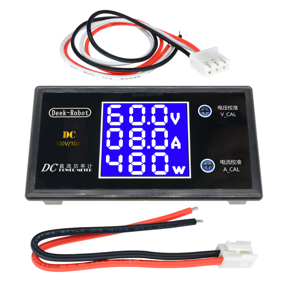
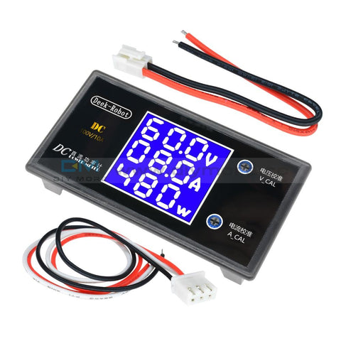 Translation missing: en.products.product.regular_price $7.99{"id":4417209073735,"title":"AC Digital Multifunction Meter Watt Power Volt Amp TTL Current Test Module PZEM 004T With Coil 0 100A 80 260V AC For Arduino","handle":"ac-digital-multifunction-meter-watt-power-volt-amp-ttl-current-test-module-pzem-004t-with-coil-0-100a-80-260v-ac-for-arduino","description":"\u003cdiv\u003e\n\u003cwidget data-widget-type=\"customText\" id=\"23614578\" title=\"011086\" type=\"custom\"\u003e\u003c\/widget\u003e \u003cp\u003e \u003c\/p\u003e \u003cp\u003e \u003c\/p\u003e \u003cp\u003e \u003cimg alt=\"HTB1ZYSui4PI8KJjSspoq6x6MFXaU\" height=\"40\" src=\"https:\/\/ae01.alicdn.com\/kf\/HTB1ZYSui4PI8KJjSspoq6x6MFXaU.jpg\" width=\"950\"\u003e \u003c\/p\u003e \u003cp\u003e \u003c\/p\u003e \u003cdiv\u003e \u003cspan style=\"font-size: 18.0px;\"\u003e\u003cspan style=\"font-family: arial , helvetica , sans-serif;\"\u003e\u003cstrong\u003eModel: PZEM-004T\u003c\/strong\u003e\u003c\/span\u003e\u003c\/span\u003e \u003c\/div\u003e \u003cdiv\u003e \u003c\/div\u003e \u003cdiv\u003e \u003cdiv\u003e \u003cspan style=\"font-size: 18.0px;\"\u003e\u003cspan style=\"font-family: arial , helvetica , sans-serif;\"\u003eOverview\u003c\/span\u003e\u003c\/span\u003e \u003c\/div\u003e \u003cdiv\u003e \u003cspan style=\"font-size: 18.0px;\"\u003e\u003cspan style=\"font-family: arial , helvetica , sans-serif;\"\u003eThis document describes the specification of the PZEM-004T AC communication module,\u003c\/span\u003e\u003c\/span\u003e \u003c\/div\u003e \u003cdiv\u003e \u003cspan style=\"font-size: 18.0px;\"\u003e\u003cspan style=\"font-family: arial , helvetica , sans-serif;\"\u003ethe module is mainly used for measuring AC voltage, current, active power, frequency, power\u003c\/span\u003e\u003c\/span\u003e \u003c\/div\u003e \u003cdiv\u003e \u003cspan style=\"font-size: 18.0px;\"\u003e\u003cspan style=\"font-family: arial , helvetica , sans-serif;\"\u003efactor and active energy, the module is without display function, the data is read through the TTL\u003c\/span\u003e\u003c\/span\u003e \u003c\/div\u003e \u003cdiv\u003e \u003cspan style=\"font-size: 18.0px;\"\u003e\u003cspan style=\"font-family: arial , helvetica , sans-serif;\"\u003einterface.\u003c\/span\u003e\u003c\/span\u003e \u003c\/div\u003e \u003cdiv\u003e \u003cspan style=\"font-size: 18.0px;\"\u003e\u003cspan style=\"font-family: arial , helvetica , sans-serif;\"\u003ePZEM-004T-10A: Measuring Range 10A (Built-in Shunt)\u003c\/span\u003e\u003c\/span\u003e \u003c\/div\u003e \u003cdiv\u003e \u003cspan style=\"font-size: 18.0px;\"\u003e\u003cspan style=\"font-family: arial , helvetica , sans-serif;\"\u003ePZEM-004T-100A: Measuring Range 100A (external transformer)\u003c\/span\u003e\u003c\/span\u003e \u003c\/div\u003e \u003cdiv\u003e \u003cspan style=\"font-size: 18.0px;\"\u003e\u003cspan style=\"font-family: arial , helvetica , sans-serif;\"\u003e1.Function description\u003c\/span\u003e\u003c\/span\u003e \u003c\/div\u003e \u003cdiv\u003e \u003cspan style=\"font-size: 18.0px;\"\u003e\u003cspan style=\"font-family: arial , helvetica , sans-serif;\"\u003e1.1 Voltage\u003c\/span\u003e\u003c\/span\u003e \u003c\/div\u003e \u003cdiv\u003e \u003cspan style=\"font-size: 18.0px;\"\u003e\u003cspan style=\"font-family: arial , helvetica , sans-serif;\"\u003e1.1.1 Measuring range:80~260V\u003c\/span\u003e\u003c\/span\u003e \u003c\/div\u003e \u003cdiv\u003e \u003cspan style=\"font-size: 18.0px;\"\u003e\u003cspan style=\"font-family: arial , helvetica , sans-serif;\"\u003e1.1.2 Resolution: 0.1V\u003c\/span\u003e\u003c\/span\u003e \u003c\/div\u003e \u003cdiv\u003e \u003cspan style=\"font-size: 18.0px;\"\u003e\u003cspan style=\"font-family: arial , helvetica , sans-serif;\"\u003e1.1.3 Measurement accuracy: 0.5%\u003c\/span\u003e\u003c\/span\u003e \u003c\/div\u003e \u003cdiv\u003e \u003cspan style=\"font-size: 18.0px;\"\u003e\u003cspan style=\"font-family: arial , helvetica , sans-serif;\"\u003e1.2 Current\u003c\/span\u003e\u003c\/span\u003e \u003c\/div\u003e \u003cdiv\u003e \u003cspan style=\"font-size: 18.0px;\"\u003e\u003cspan style=\"font-family: arial , helvetica , sans-serif;\"\u003e1.2.1 Measuring range: 0~10A(PZEM-004T-10A); 0~100A(PZEM-004T-100A)\u003c\/span\u003e\u003c\/span\u003e \u003c\/div\u003e \u003cdiv\u003e \u003cspan style=\"font-size: 18.0px;\"\u003e\u003cspan style=\"font-family: arial , helvetica , sans-serif;\"\u003e1.2.2 Starting measure current: 0.01A(PZEM-004T-10A); 0.02A(PZEM-004T-100A)\u003c\/span\u003e\u003c\/span\u003e \u003c\/div\u003e \u003cdiv\u003e \u003cspan style=\"font-size: 18.0px;\"\u003e\u003cspan style=\"font-family: arial , helvetica , sans-serif;\"\u003e1.2.3 Resolution: 0.001A\u003c\/span\u003e\u003c\/span\u003e \u003c\/div\u003e \u003cdiv\u003e \u003cspan style=\"font-size: 18.0px;\"\u003e\u003cspan style=\"font-family: arial , helvetica , sans-serif;\"\u003e1.2.4 Measurement accuracy: 0.5%\u003c\/span\u003e\u003c\/span\u003e \u003c\/div\u003e \u003cdiv\u003e \u003cspan style=\"font-size: 18.0px;\"\u003e\u003cspan style=\"font-family: arial , helvetica , sans-serif;\"\u003e1.3 Active power\u003c\/span\u003e\u003c\/span\u003e \u003c\/div\u003e \u003cdiv\u003e \u003cspan style=\"font-size: 18.0px;\"\u003e\u003cspan style=\"font-family: arial , helvetica , sans-serif;\"\u003e1.3.1 Measuring range: 0~2.3kW(PZEM-004T-10A); 0~23kW(PZEM-004T-100A)\u003c\/span\u003e\u003c\/span\u003e \u003c\/div\u003e \u003cdiv\u003e \u003cspan style=\"font-size: 18.0px;\"\u003e\u003cspan style=\"font-family: arial , helvetica , sans-serif;\"\u003e1.3.2 Starting measure power: 0.4W\u003c\/span\u003e\u003c\/span\u003e \u003c\/div\u003e \u003cdiv\u003e \u003cspan style=\"font-size: 18.0px;\"\u003e\u003cspan style=\"font-family: arial , helvetica , sans-serif;\"\u003e1.3.3 Resolution: 0.1W\u003c\/span\u003e\u003c\/span\u003e \u003c\/div\u003e \u003cdiv\u003e \u003cspan style=\"font-size: 18.0px;\"\u003e\u003cspan style=\"font-family: arial , helvetica , sans-serif;\"\u003e1.3.4 Display format:\u003c\/span\u003e\u003c\/span\u003e \u003c\/div\u003e \u003cdiv\u003e \u003cspan style=\"font-size: 18.0px;\"\u003e\u003cspan style=\"font-family: arial , helvetica , sans-serif;\"\u003e<1000W, it display one decimal, such as: 999.9W\u003c\/span\u003e\u003c\/span\u003e \u003c\/div\u003e \u003cdiv\u003e \u003cspan style=\"font-size: 18.0px;\"\u003e\u003cspan style=\"font-family: arial , helvetica , sans-serif;\"\u003ege1000W, it display only integer, such as: 1000W\u003c\/span\u003e\u003c\/span\u003e \u003c\/div\u003e \u003cdiv\u003e \u003cspan style=\"font-size: 18.0px;\"\u003e\u003cspan style=\"font-family: arial , helvetica , sans-serif;\"\u003e1.3.5 Measurement accuracy: 0.5%\u003c\/span\u003e\u003c\/span\u003e \u003c\/div\u003e \u003cdiv\u003e \u003cspan style=\"font-size: 18.0px;\"\u003e\u003cspan style=\"font-family: arial , helvetica , sans-serif;\"\u003e1.4 Power factor\u003c\/span\u003e\u003c\/span\u003e \u003c\/div\u003e \u003cdiv\u003e \u003cspan style=\"font-size: 18.0px;\"\u003e\u003cspan style=\"font-family: arial , helvetica , sans-serif;\"\u003e1.4.1 Measuring range: 0.00~1.00\u003c\/span\u003e\u003c\/span\u003e \u003c\/div\u003e \u003cdiv\u003e \u003cspan style=\"font-size: 18.0px;\"\u003e\u003cspan style=\"font-family: arial , helvetica , sans-serif;\"\u003e1.4.2 Resolution: 0.01\u003c\/span\u003e\u003c\/span\u003e \u003c\/div\u003e \u003cdiv\u003e \u003cspan style=\"font-size: 18.0px;\"\u003e\u003cspan style=\"font-family: arial , helvetica , sans-serif;\"\u003e1.4.3 Measurement accuracy: 1%\u003c\/span\u003e\u003c\/span\u003e \u003c\/div\u003e \u003cdiv\u003e \u003cspan style=\"font-size: 18.0px;\"\u003e\u003cspan style=\"font-family: arial , helvetica , sans-serif;\"\u003e1.5 Frequency\u003c\/span\u003e\u003c\/span\u003e \u003c\/div\u003e \u003cdiv\u003e \u003cspan style=\"font-size: 18.0px;\"\u003e\u003cspan style=\"font-family: arial , helvetica , sans-serif;\"\u003e1.5.1 Measuring range: 45Hz~65Hz\u003c\/span\u003e\u003c\/span\u003e \u003c\/div\u003e \u003cdiv\u003e \u003cspan style=\"font-size: 18.0px;\"\u003e\u003cspan style=\"font-family: arial , helvetica , sans-serif;\"\u003e1.5.2 Resolution: 0.1Hz\u003c\/span\u003e\u003c\/span\u003e \u003c\/div\u003e \u003cdiv\u003e \u003cspan style=\"font-size: 18.0px;\"\u003e\u003cspan style=\"font-family: arial , helvetica , sans-serif;\"\u003e1.5.3 Measurement accuracy: 0.5%\u003c\/span\u003e\u003c\/span\u003e \u003c\/div\u003e \u003cdiv\u003e \u003cspan style=\"font-size: 18.0px;\"\u003e\u003cspan style=\"font-family: arial , helvetica , sans-serif;\"\u003e1.6 Active energy\u003c\/span\u003e\u003c\/span\u003e \u003c\/div\u003e \u003cdiv\u003e \u003cspan style=\"font-size: 18.0px;\"\u003e\u003cspan style=\"font-family: arial , helvetica , sans-serif;\"\u003e1.6.1 Measuring range: 0~9999.99kWh\u003c\/span\u003e\u003c\/span\u003e \u003c\/div\u003e \u003cdiv\u003e \u003cspan style=\"font-size: 18.0px;\"\u003e\u003cspan style=\"font-family: arial , helvetica , sans-serif;\"\u003e1.6.2 Resolution: 1Wh\u003c\/span\u003e\u003c\/span\u003e \u003c\/div\u003e \u003cdiv\u003e \u003cspan style=\"font-size: 18.0px;\"\u003e\u003cspan style=\"font-family: arial , helvetica , sans-serif;\"\u003e1.6.3 Measurement accuracy: 0.5%\u003c\/span\u003e\u003c\/span\u003e \u003c\/div\u003e \u003cdiv\u003e \u003cspan style=\"font-size: 18.0px;\"\u003e\u003cspan style=\"font-family: arial , helvetica , sans-serif;\"\u003e1.6.4 Display format:\u003c\/span\u003e\u003c\/span\u003e \u003c\/div\u003e \u003cdiv\u003e \u003cspan style=\"font-size: 18.0px;\"\u003e\u003cspan style=\"font-family: arial , helvetica , sans-serif;\"\u003e<10kWh, the display unit is Wh(1kWh=1000Wh), such as: 9999Wh\u003c\/span\u003e\u003c\/span\u003e \u003c\/div\u003e \u003cdiv\u003e \u003cspan style=\"font-size: 18.0px;\"\u003e\u003cspan style=\"font-family: arial , helvetica , sans-serif;\"\u003ege10kWh, the display unit is kWh, such as: 9999.99kWh\u003c\/span\u003e\u003c\/span\u003e \u003c\/div\u003e \u003cdiv\u003e \u003cspan style=\"font-size: 18.0px;\"\u003e\u003cspan style=\"font-family: arial , helvetica , sans-serif;\"\u003e1.6.5 Reset energy: use software to reset.\u003c\/span\u003e\u003c\/span\u003e \u003c\/div\u003e \u003cdiv\u003e \u003cspan style=\"font-size: 18.0px;\"\u003e\u003cspan style=\"font-family: arial , helvetica , sans-serif;\"\u003e1.7 Over power alarm\u003c\/span\u003e\u003c\/span\u003e \u003c\/div\u003e \u003cdiv\u003e \u003cspan style=\"font-size: 18.0px;\"\u003e\u003cspan style=\"font-family: arial , helvetica , sans-serif;\"\u003eActive power threshold can be set, when the measured active power exceeds the threshold, it\u003c\/span\u003e\u003c\/span\u003e \u003c\/div\u003e \u003cdiv\u003e \u003cspan style=\"font-size: 18.0px;\"\u003e\u003cspan style=\"font-family: arial , helvetica , sans-serif;\"\u003ecan alarm\u003c\/span\u003e\u003c\/span\u003e \u003c\/div\u003e \u003cdiv\u003e \u003cspan style=\"font-size: 18.0px;\"\u003e\u003cspan style=\"font-family: arial , helvetica , sans-serif;\"\u003e1.8 Communication interface\u003c\/span\u003e\u003c\/span\u003e \u003c\/div\u003e \u003cdiv\u003e \u003cspan style=\"font-size: 18.0px;\"\u003e\u003cspan style=\"font-family: arial , helvetica , sans-serif;\"\u003eRS485 interface。\u003c\/span\u003e\u003c\/span\u003e \u003c\/div\u003e \u003cdiv\u003e \u003cspan style=\"font-size: 18.0px;\"\u003e\u003cspan style=\"font-family: arial , helvetica , sans-serif;\"\u003e2 Communication protocol\u003c\/span\u003e\u003c\/span\u003e \u003c\/div\u003e \u003cdiv\u003e \u003cspan style=\"font-size: 18.0px;\"\u003e\u003cspan style=\"font-family: arial , helvetica , sans-serif;\"\u003e2.1 Physical layer protocol\u003c\/span\u003e\u003c\/span\u003e \u003c\/div\u003e \u003cdiv\u003e \u003cspan style=\"font-size: 18.0px;\"\u003e\u003cspan style=\"font-family: arial , helvetica , sans-serif;\"\u003ePhysical layer use UART to RS485 communication interface\u003c\/span\u003e\u003c\/span\u003e \u003c\/div\u003e \u003cdiv\u003e \u003cspan style=\"font-size: 18.0px;\"\u003e\u003cspan style=\"font-family: arial , helvetica , sans-serif;\"\u003eBaud rate is 9600, 8 data bits, 1 stop bit, no parity\u003c\/span\u003e\u003c\/span\u003e \u003c\/div\u003e \u003cdiv\u003e \u003cspan style=\"font-size: 18.0px;\"\u003e\u003cspan style=\"font-family: arial , helvetica , sans-serif;\"\u003e2.2 Application layer protocol\u003c\/span\u003e\u003c\/span\u003e \u003c\/div\u003e \u003cdiv\u003e \u003cspan style=\"font-size: 18.0px;\"\u003e\u003cspan style=\"font-family: arial , helvetica , sans-serif;\"\u003eThe application layer use the Modbus-RTU protocol to communicate. At present, it only\u003c\/span\u003e\u003c\/span\u003e \u003c\/div\u003e \u003cdiv\u003e \u003cspan style=\"font-size: 18.0px;\"\u003e\u003cspan style=\"font-family: arial , helvetica , sans-serif;\"\u003esupports function codes such as 0x03 (Read Holding Register), 0x04 (Read Input Register), 0x06\u003c\/span\u003e\u003c\/span\u003e \u003c\/div\u003e \u003cdiv\u003e \u003cspan style=\"font-size: 18.0px;\"\u003e\u003cspan style=\"font-family: arial , helvetica , sans-serif;\"\u003e(Write Single Register), 0x41 (Calibration), 0x42 (Reset energy).etc.\u003c\/span\u003e\u003c\/span\u003e \u003c\/div\u003e \u003cdiv\u003e \u003cspan style=\"font-size: 18.0px;\"\u003e\u003cspan style=\"font-family: arial , helvetica , sans-serif;\"\u003e0x41 function code is only for internal use (address can be only 0xF8), used for factory\u003c\/span\u003e\u003c\/span\u003e \u003c\/div\u003e \u003cdiv\u003e \u003cspan style=\"font-size: 18.0px;\"\u003e\u003cspan style=\"font-family: arial , helvetica , sans-serif;\"\u003ecalibration and return to factory maintenance occasions, after the function code to increase 16-bit\u003c\/span\u003e\u003c\/span\u003e \u003c\/div\u003e \u003cdiv\u003e \u003cspan style=\"font-size: 18.0px;\"\u003e\u003cspan style=\"font-family: arial , helvetica , sans-serif;\"\u003epassword, the default password is 0x3721\u003c\/span\u003e\u003c\/span\u003e \u003c\/div\u003e \u003cdiv\u003e \u003cspan style=\"font-size: 18.0px;\"\u003e\u003cspan style=\"font-family: arial , helvetica , sans-serif;\"\u003eThe address range of the slave is 0x01 ~ 0xF7. The address 0x00 is used as the broadcast\u003c\/span\u003e\u003c\/span\u003e \u003c\/div\u003e \u003cdiv\u003e \u003cspan style=\"font-size: 18.0px;\"\u003e\u003cspan style=\"font-family: arial , helvetica , sans-serif;\"\u003eaddress, the slave does not need to reply the master. The address 0xF8 is used as the general\u003c\/span\u003e\u003c\/span\u003e \u003c\/div\u003e \u003cdiv\u003e \u003cspan style=\"font-size: 18.0px;\"\u003e\u003cspan style=\"font-family: arial , helvetica , sans-serif;\"\u003eaddress, this address can be only used in single-slave environment and can be used for calibration\u003c\/span\u003e\u003c\/span\u003e \u003c\/div\u003e \u003cdiv\u003e \u003cspan style=\"font-size: 18.0px;\"\u003e\u003cspan style=\"font-family: arial , helvetica , sans-serif;\"\u003eetc.operation.\u003c\/span\u003e\u003c\/span\u003e \u003c\/div\u003e \u003cdiv\u003e \u003cspan style=\"font-size: 18.0px;\"\u003e\u003cspan style=\"font-family: arial , helvetica , sans-serif;\"\u003e2.3 Read the measurement result\u003c\/span\u003e\u003c\/span\u003e \u003c\/div\u003e \u003cdiv\u003e \u003cspan style=\"font-size: 18.0px;\"\u003e\u003cspan style=\"font-family: arial , helvetica , sans-serif;\"\u003eThe command format of the master reads the measurement result is(total of 8 bytes):\u003c\/span\u003e\u003c\/span\u003e \u003c\/div\u003e \u003cdiv\u003e \u003cspan style=\"font-size: 18.0px;\"\u003e\u003cspan style=\"font-family: arial , helvetica , sans-serif;\"\u003eSlave Address + 0x04 + Register Address High Byte + Register Address Low Byte + Number\u003c\/span\u003e\u003c\/span\u003e \u003c\/div\u003e \u003cdiv\u003e \u003cspan style=\"font-size: 18.0px;\"\u003e\u003cspan style=\"font-family: arial , helvetica , sans-serif;\"\u003eof Registers High Byte + Number of Registers Low Byte + CRC Check High Byte + CRC Check\u003c\/span\u003e\u003c\/span\u003e \u003c\/div\u003e \u003cdiv\u003e \u003cspan style=\"font-size: 18.0px;\"\u003e\u003cspan style=\"font-family: arial , helvetica , sans-serif;\"\u003eLow Byte.\u003c\/span\u003e\u003c\/span\u003e \u003c\/div\u003e \u003cdiv\u003e \u003cspan style=\"font-size: 18.0px;\"\u003e\u003cspan style=\"font-family: arial , helvetica , sans-serif;\"\u003eThe command format of the reply from the slave is divided into two kinds:\u003c\/span\u003e\u003c\/span\u003e \u003c\/div\u003e \u003cdiv\u003e \u003cspan style=\"font-size: 18.0px;\"\u003e\u003cspan style=\"font-family: arial , helvetica , sans-serif;\"\u003eCorrect Reply: Slave Address + 0x04 + Number of Bytes + Register 1 Data High Byte +\u003c\/span\u003e\u003c\/span\u003e \u003c\/div\u003e \u003cdiv\u003e \u003cspan style=\"font-size: 18.0px;\"\u003e\u003cspan style=\"font-family: arial , helvetica , sans-serif;\"\u003eRegister 1 Data Low Byte + ... + CRC Check High Byte + CRC Check Low Byte\u003c\/span\u003e\u003c\/span\u003e \u003c\/div\u003e \u003cdiv\u003e \u003cspan style=\"font-size: 18.0px;\"\u003e\u003cspan style=\"font-family: arial , helvetica , sans-serif;\"\u003eError Reply: Slave address + 0x84 + Abnormal code + CRC check high byte + CRC check\u003c\/span\u003e\u003c\/span\u003e \u003c\/div\u003e \u003cdiv\u003e \u003cspan style=\"font-size: 18.0px;\"\u003e\u003cspan style=\"font-family: arial , helvetica , sans-serif;\"\u003elow byte\u003c\/span\u003e\u003c\/span\u003e \u003c\/div\u003e \u003cdiv\u003e \u003cspan style=\"font-size: 18.0px;\"\u003e\u003cspan style=\"font-family: arial , helvetica , sans-serif;\"\u003eAbnormal code analyzed as following (the same below)\u003c\/span\u003e\u003c\/span\u003e \u003c\/div\u003e \u003cdiv\u003e \u003cspan style=\"font-size: 18.0px;\"\u003e\u003cspan style=\"font-family: arial , helvetica , sans-serif;\"\u003e⚫ 0x01,Illegal function\u003c\/span\u003e\u003c\/span\u003e \u003c\/div\u003e \u003cdiv\u003e \u003cspan style=\"font-size: 18.0px;\"\u003e\u003cspan style=\"font-family: arial , helvetica , sans-serif;\"\u003e⚫ 0x02,Illegal address\u003c\/span\u003e\u003c\/span\u003e \u003c\/div\u003e \u003cdiv\u003e \u003cspan style=\"font-size: 18.0px;\"\u003e\u003cspan style=\"font-family: arial , helvetica , sans-serif;\"\u003e⚫ 0x03,Illegal data\u003c\/span\u003e\u003c\/span\u003e \u003c\/div\u003e \u003c\/div\u003e \u003cdiv\u003e \u003cspan style=\"font-family: arial , helvetica , sans-serif;font-size: 18.0px;\"\u003e⚫ 0x04,Slave error\u003c\/span\u003e \u003cspan style=\"font-family: arial , helvetica , sans-serif;font-size: 18.0px;\"\u003e \u003c\/span\u003e \u003c\/div\u003e \u003cdiv\u003e \u003cspan style=\"font-family: arial , helvetica , sans-serif;font-size: 18.0px;\"\u003e\u003cimg alt=\"1\" src=\"https:\/\/ae01.alicdn.com\/kf\/HTB1hnE1RzTpK1RjSZKPq6y3UpXaT.jpg\"\u003e\u003c\/span\u003e \u003c\/div\u003e \u003cdiv\u003e \u003c\/div\u003e \u003cdiv\u003e \u003cspan style=\"font-family: arial , helvetica , sans-serif;font-size: 18.0px;\"\u003eFor example, the master sends the following command (CRC check code is replaced by\u003c\/span\u003e \u003c\/div\u003e \u003cdiv\u003e \u003cspan style=\"font-size: 18.0px;\"\u003e\u003cspan style=\"font-family: arial , helvetica , sans-serif;\"\u003e0xHH and 0xLL, the same below)\u003c\/span\u003e\u003c\/span\u003e \u003c\/div\u003e \u003cdiv\u003e \u003cspan style=\"font-size: 18.0px;\"\u003e\u003cspan style=\"font-family: arial , helvetica , sans-serif;\"\u003e0x01 + 0x04 + 0x00 + 0x00 + 0x00 + 0x0A + 0xHH + 0xLL\u003c\/span\u003e\u003c\/span\u003e \u003c\/div\u003e \u003cdiv\u003e \u003cspan style=\"font-size: 18.0px;\"\u003e\u003cspan style=\"font-family: arial , helvetica , sans-serif;\"\u003eIndicates that the master needs to read 10 registers with slave address 0x01 and the start\u003c\/span\u003e\u003c\/span\u003e \u003c\/div\u003e \u003cdiv\u003e \u003cspan style=\"font-size: 18.0px;\"\u003e\u003cspan style=\"font-family: arial , helvetica , sans-serif;\"\u003eaddress of the register is 0x0000\u003c\/span\u003e\u003c\/span\u003e \u003c\/div\u003e \u003cdiv\u003e \u003cspan style=\"font-size: 18.0px;\"\u003e\u003cspan style=\"font-family: arial , helvetica , sans-serif;\"\u003eThe correct reply from the slave is as following:\u003c\/span\u003e\u003c\/span\u003e \u003c\/div\u003e \u003cdiv\u003e \u003cspan style=\"font-size: 18.0px;\"\u003e\u003cspan style=\"font-family: arial , helvetica , sans-serif;\"\u003e0x01 + 0x04 + 0x14 + 0x08 + 0x98 + 0x03 + 0xE8+0x00 + 0x00 +0x08 + 0x98+ 0x00 +\u003c\/span\u003e\u003c\/span\u003e \u003c\/div\u003e \u003cdiv\u003e \u003cspan style=\"font-size: 18.0px;\"\u003e\u003cspan style=\"font-family: arial , helvetica , sans-serif;\"\u003e0x00 + 0x00 + 0x00 + 0x00 + 0x00 + 0x01 + 0xF4 + 0x00 + 0x64 + 0x00 + 0x00 + 0xHH + 0xLL\u003c\/span\u003e\u003c\/span\u003e \u003c\/div\u003e \u003cdiv\u003e \u003cspan style=\"font-size: 18.0px;\"\u003e\u003cspan style=\"font-family: arial , helvetica , sans-serif;\"\u003eThe above data shows\u003c\/span\u003e\u003c\/span\u003e \u003c\/div\u003e \u003cdiv\u003e \u003cspan style=\"font-size: 18.0px;\"\u003e\u003cspan style=\"font-family: arial , helvetica , sans-serif;\"\u003e⚫ Voltage is 0x0898, converted to decimal is 2200, display 220.0V\u003c\/span\u003e\u003c\/span\u003e \u003c\/div\u003e \u003cdiv\u003e \u003cspan style=\"font-size: 18.0px;\"\u003e\u003cspan style=\"font-family: arial , helvetica , sans-serif;\"\u003e⚫ Current is 0x000003E8, converted to decimal is 1000, display 1.000A\u003c\/span\u003e\u003c\/span\u003e \u003c\/div\u003e \u003cdiv\u003e \u003cspan style=\"font-size: 18.0px;\"\u003e\u003cspan style=\"font-family: arial , helvetica , sans-serif;\"\u003e⚫ Power is 0x00000898, converted to decimal is 2200, display 220.0W\u003c\/span\u003e\u003c\/span\u003e \u003c\/div\u003e \u003cdiv\u003e \u003cspan style=\"font-size: 18.0px;\"\u003e\u003cspan style=\"font-family: arial , helvetica , sans-serif;\"\u003e⚫ Energy is 0x00000000, converted to decimal is 0, display 0Wh\u003c\/span\u003e\u003c\/span\u003e \u003c\/div\u003e \u003cdiv\u003e \u003cspan style=\"font-size: 18.0px;\"\u003e\u003cspan style=\"font-family: arial , helvetica , sans-serif;\"\u003e⚫ Frequency is 0x01F4, converted to decimal is 500, display 50.0Hz\u003c\/span\u003e\u003c\/span\u003e \u003c\/div\u003e \u003cdiv\u003e \u003cspan style=\"font-size: 18.0px;\"\u003e\u003cspan style=\"font-family: arial , helvetica , sans-serif;\"\u003e⚫ Power factor is 0x0064, converted to decimal is 100, display 1.00\u003c\/span\u003e\u003c\/span\u003e \u003c\/div\u003e \u003cdiv\u003e \u003cspan style=\"font-size: 18.0px;\"\u003e\u003cspan style=\"font-family: arial , helvetica , sans-serif;\"\u003e⚫ Alarm status is 0x0000, indicates that the current power is lower than the alarm power\u003c\/span\u003e\u003c\/span\u003e \u003c\/div\u003e \u003cdiv\u003e \u003cspan style=\"font-size: 18.0px;\"\u003e\u003cspan style=\"font-family: arial , helvetica , sans-serif;\"\u003ethreshold\u003c\/span\u003e\u003c\/span\u003e \u003c\/div\u003e \u003cdiv\u003e \u003cspan style=\"font-size: 18.0px;\"\u003e\u003cspan style=\"font-family: arial , helvetica , sans-serif;\"\u003e2.4 Read and modify the slave parameters\u003c\/span\u003e\u003c\/span\u003e \u003c\/div\u003e \u003cdiv\u003e \u003cspan style=\"font-size: 18.0px;\"\u003e\u003cspan style=\"font-family: arial , helvetica , sans-serif;\"\u003eAt present,it only supports reading and modifying slave address and power alarm threshold\u003c\/span\u003e\u003c\/span\u003e \u003c\/div\u003e \u003cdiv\u003e \u003cspan style=\"font-size: 18.0px;\"\u003e\u003cspan style=\"font-family: arial , helvetica , sans-serif;\"\u003eThe register is arranged as the following table\u003c\/span\u003e\u003c\/span\u003e \u003c\/div\u003e \u003cdiv\u003e \u003cspan style=\"font-size: 18.0px;\"\u003e\u003cspan style=\"font-family: arial , helvetica , sans-serif;\"\u003e\u003cimg alt=\"2\" src=\"https:\/\/ae01.alicdn.com\/kf\/HTB1QmhWeK3tHKVjSZSgq6x4QFXa5.jpg\"\u003e\u003c\/span\u003e\u003c\/span\u003e \u003c\/div\u003e \u003cdiv\u003e \u003c\/div\u003e \u003cdiv\u003e \u003cspan style=\"font-family: arial , helvetica , sans-serif;font-size: 18.0px;\"\u003eThe command format of the master to read the slave parameters and read the measurement\u003c\/span\u003e \u003c\/div\u003e \u003cdiv\u003e \u003cspan style=\"font-size: 18.0px;\"\u003e\u003cspan style=\"font-family: arial , helvetica , sans-serif;\"\u003eresults are same(descrybed in details in Section 2.3), only need to change the function code from\u003c\/span\u003e\u003c\/span\u003e \u003c\/div\u003e \u003cdiv\u003e \u003cspan style=\"font-size: 18.0px;\"\u003e\u003cspan style=\"font-family: arial , helvetica , sans-serif;\"\u003e0x04 to 0x03.\u003c\/span\u003e\u003c\/span\u003e \u003c\/div\u003e \u003cdiv\u003e \u003cspan style=\"font-size: 18.0px;\"\u003e\u003cspan style=\"font-family: arial , helvetica , sans-serif;\"\u003eThe command format of the master to modify the slave parameters is (total of 8 bytes):\u003c\/span\u003e\u003c\/span\u003e \u003c\/div\u003e \u003cdiv\u003e \u003cspan style=\"font-size: 18.0px;\"\u003e\u003cspan style=\"font-family: arial , helvetica , sans-serif;\"\u003eSlave Address + 0x06 + Register Address High Byte + Register Address Low Byte + Register\u003c\/span\u003e\u003c\/span\u003e \u003c\/div\u003e \u003cdiv\u003e \u003cspan style=\"font-size: 18.0px;\"\u003e\u003cspan style=\"font-family: arial , helvetica , sans-serif;\"\u003eValue High Byte + Register Value Low Byte + CRC Check High Byte + CRC Check Low Byte.\u003c\/span\u003e\u003c\/span\u003e \u003c\/div\u003e \u003cdiv\u003e \u003cspan style=\"font-size: 18.0px;\"\u003e\u003cspan style=\"font-family: arial , helvetica , sans-serif;\"\u003eThe command format of the reply from the slave is divided into two kinds:\u003c\/span\u003e\u003c\/span\u003e \u003c\/div\u003e \u003cdiv\u003e \u003cspan style=\"font-size: 18.0px;\"\u003e\u003cspan style=\"font-family: arial , helvetica , sans-serif;\"\u003eCorrect Response: Slave Address + 0x06 + Number of Bytes + Register Address Low Byte +\u003c\/span\u003e\u003c\/span\u003e \u003c\/div\u003e \u003cdiv\u003e \u003cspan style=\"font-size: 18.0px;\"\u003e\u003cspan style=\"font-family: arial , helvetica , sans-serif;\"\u003eRegister Value High Byte + Register Value Low Byte + CRC Check High Byte + CRC Check Low\u003c\/span\u003e\u003c\/span\u003e \u003c\/div\u003e \u003cdiv\u003e \u003cspan style=\"font-size: 18.0px;\"\u003e\u003cspan style=\"font-family: arial , helvetica , sans-serif;\"\u003eByte.\u003c\/span\u003e\u003c\/span\u003e \u003c\/div\u003e \u003cdiv\u003e \u003cspan style=\"font-size: 18.0px;\"\u003e\u003cspan style=\"font-family: arial , helvetica , sans-serif;\"\u003eError Reply: Slave address + 0x86 + Abnormal code + CRC check high byte + CRC check\u003c\/span\u003e\u003c\/span\u003e \u003c\/div\u003e \u003cdiv\u003e \u003cspan style=\"font-size: 18.0px;\"\u003e\u003cspan style=\"font-family: arial , helvetica , sans-serif;\"\u003elow byte.\u003c\/span\u003e\u003c\/span\u003e \u003c\/div\u003e \u003cdiv\u003e \u003cspan style=\"font-size: 18.0px;\"\u003e\u003cspan style=\"font-family: arial , helvetica , sans-serif;\"\u003eFor example, the master sets the slave's power alarm threshold:\u003c\/span\u003e\u003c\/span\u003e \u003c\/div\u003e \u003cdiv\u003e \u003cspan style=\"font-size: 18.0px;\"\u003e\u003cspan style=\"font-family: arial , helvetica , sans-serif;\"\u003e0x01 + 0x06 + 0x00 + 0x01 + 0x08 + 0xFC + 0xHH + 0xLL\u003c\/span\u003e\u003c\/span\u003e \u003c\/div\u003e \u003cdiv\u003e \u003cspan style=\"font-size: 18.0px;\"\u003e\u003cspan style=\"font-family: arial , helvetica , sans-serif;\"\u003eIndicates that the master needs to set the 0x0001 register (power alarm threshold) to 0x08FC\u003c\/span\u003e\u003c\/span\u003e \u003c\/div\u003e \u003cdiv\u003e \u003cspan style=\"font-size: 18.0px;\"\u003e\u003cspan style=\"font-family: arial , helvetica , sans-serif;\"\u003e(2300W).\u003c\/span\u003e\u003c\/span\u003e \u003c\/div\u003e \u003cdiv\u003e \u003cspan style=\"font-size: 18.0px;\"\u003e\u003cspan style=\"font-family: arial , helvetica , sans-serif;\"\u003eSet up correctly, the slave return to the data which is sent from the master.\u003c\/span\u003e\u003c\/span\u003e \u003c\/div\u003e \u003cdiv\u003e \u003cspan style=\"font-size: 18.0px;\"\u003e\u003cspan style=\"font-family: arial , helvetica , sans-serif;\"\u003eFor example, the master sets the address of the slave\u003c\/span\u003e\u003c\/span\u003e \u003c\/div\u003e \u003cdiv\u003e \u003cspan style=\"font-size: 18.0px;\"\u003e\u003cspan style=\"font-family: arial , helvetica , sans-serif;\"\u003e0x01 + 0x06 + 0x00 + 0x02 + 0x00 + 0x05 + 0xHH + 0xLL\u003c\/span\u003e\u003c\/span\u003e \u003c\/div\u003e \u003cdiv\u003e \u003cspan style=\"font-size: 18.0px;\"\u003e\u003cspan style=\"font-family: arial , helvetica , sans-serif;\"\u003eIndicates that the master needs to set the 0x0002 register (Modbus-RTU address) to 0x0005\u003c\/span\u003e\u003c\/span\u003e \u003c\/div\u003e \u003cdiv\u003e \u003cspan style=\"font-size: 18.0px;\"\u003e\u003cspan style=\"font-family: arial , helvetica , sans-serif;\"\u003eSet up correctly, the slave return to the data which is sent from the master.\u003c\/span\u003e\u003c\/span\u003e \u003c\/div\u003e \u003cdiv\u003e \u003cspan style=\"font-size: 18.0px;\"\u003e\u003cspan style=\"font-family: arial , helvetica , sans-serif;\"\u003e2.5 Reset energy\u003c\/span\u003e\u003c\/span\u003e \u003c\/div\u003e \u003cdiv\u003e \u003cspan style=\"font-size: 18.0px;\"\u003e\u003cspan style=\"font-family: arial , helvetica , sans-serif;\"\u003eThe command format of the master to reset the slave's energy is (total 4 bytes):\u003c\/span\u003e\u003c\/span\u003e \u003c\/div\u003e \u003cdiv\u003e \u003cspan style=\"font-size: 18.0px;\"\u003e\u003cspan style=\"font-family: arial , helvetica , sans-serif;\"\u003eSlave address + 0x42 + CRC check high byte + CRC check low byte.\u003c\/span\u003e\u003c\/span\u003e \u003c\/div\u003e \u003cdiv\u003e \u003cspan style=\"font-size: 18.0px;\"\u003e\u003cspan style=\"font-family: arial , helvetica , sans-serif;\"\u003eCorrect reply: slave address + 0x42 + CRC check high byte + CRC check low byte.\u003c\/span\u003e\u003c\/span\u003e \u003c\/div\u003e \u003cdiv\u003e \u003cspan style=\"font-size: 18.0px;\"\u003e\u003cspan style=\"font-family: arial , helvetica , sans-serif;\"\u003eError Reply: Slave address + 0xC2 + Abnormal code + CRC check high byte + CRC check\u003c\/span\u003e\u003c\/span\u003e \u003c\/div\u003e \u003cdiv\u003e \u003cspan style=\"font-size: 18.0px;\"\u003e\u003cspan style=\"font-family: arial , helvetica , sans-serif;\"\u003elow byte\u003c\/span\u003e\u003c\/span\u003e \u003c\/div\u003e \u003cdiv\u003e \u003cspan style=\"font-size: 18.0px;\"\u003e\u003cspan style=\"font-family: arial , helvetica , sans-serif;\"\u003e2.6 Calibration\u003c\/span\u003e\u003c\/span\u003e \u003c\/div\u003e \u003cdiv\u003e \u003cspan style=\"font-size: 18.0px;\"\u003e\u003cspan style=\"font-family: arial , helvetica , sans-serif;\"\u003eThe command format of the master to calibrate the slave is (total 6 bytes):\u003c\/span\u003e\u003c\/span\u003e \u003c\/div\u003e \u003cdiv\u003e \u003cspan style=\"font-size: 18.0px;\"\u003e\u003cspan style=\"font-family: arial , helvetica , sans-serif;\"\u003e0xF8 + 0x41 + 0x37 + 0x21 + CRC check high byte + CRC check low byte.\u003c\/span\u003e\u003c\/span\u003e \u003c\/div\u003e \u003cdiv\u003e \u003cspan style=\"font-size: 18.0px;\"\u003e\u003cspan style=\"font-family: arial , helvetica , sans-serif;\"\u003eCorrect reply: 0xF8 + 0x41 + 0x37 + 0x21 + CRC check high byte + CRC check low byte.\u003c\/span\u003e\u003c\/span\u003e \u003c\/div\u003e \u003cdiv\u003e \u003cspan style=\"font-size: 18.0px;\"\u003e\u003cspan style=\"font-family: arial , helvetica , sans-serif;\"\u003eError Reply: 0xF8 + 0xC1 + Abnormal code + CRC check high byte + CRC check low byte.\u003c\/span\u003e\u003c\/span\u003e \u003c\/div\u003e \u003cdiv\u003e \u003cspan style=\"font-size: 18.0px;\"\u003e\u003cspan style=\"font-family: arial , helvetica , sans-serif;\"\u003eIt should be noted that the calibration takes 3 to 4 seconds, after the master sends the\u003c\/span\u003e\u003c\/span\u003e \u003c\/div\u003e \u003cdiv\u003e \u003cspan style=\"font-size: 18.0px;\"\u003e\u003cspan style=\"font-family: arial , helvetica , sans-serif;\"\u003ecommand, if the calibration is successful, it will take 3 ~ 4 seconds to receive the response from\u003c\/span\u003e\u003c\/span\u003e \u003c\/div\u003e \u003cdiv\u003e \u003cspan style=\"font-size: 18.0px;\"\u003e\u003cspan style=\"font-family: arial , helvetica , sans-serif;\"\u003ethe slave.\u003c\/span\u003e\u003c\/span\u003e \u003c\/div\u003e \u003cdiv\u003e \u003cspan style=\"font-size: 18.0px;\"\u003e\u003cspan style=\"font-family: arial , helvetica , sans-serif;\"\u003e2.7 CRC check\u003c\/span\u003e\u003c\/span\u003e \u003c\/div\u003e \u003cdiv\u003e \u003cspan style=\"font-size: 18.0px;\"\u003e\u003cspan style=\"font-family: arial , helvetica , sans-serif;\"\u003eCRC check use 16bits format, occupy two bytes, the generator polynomial is X16 + X15 +\u003c\/span\u003e\u003c\/span\u003e \u003c\/div\u003e \u003cdiv\u003e \u003cspan style=\"font-size: 18.0px;\"\u003e\u003cspan style=\"font-family: arial , helvetica , sans-serif;\"\u003eX2 +1, the polynomial value used for calculation is 0xA001.\u003c\/span\u003e\u003c\/span\u003e \u003c\/div\u003e \u003cdiv\u003e \u003cspan style=\"font-size: 18.0px;\"\u003e\u003cspan style=\"font-family: arial , helvetica , sans-serif;\"\u003eThe value of the CRC check is a frame data divide all results of checking all the bytes except\u003c\/span\u003e\u003c\/span\u003e \u003c\/div\u003e \u003cdiv\u003e \u003cspan style=\"font-size: 18.0px;\"\u003e\u003cspan style=\"font-family: arial , helvetica , sans-serif;\"\u003ethe CRC check value.\u003c\/span\u003e\u003c\/span\u003e \u003c\/div\u003e \u003cdiv\u003e \u003cspan style=\"font-size: 18.0px;\"\u003e\u003cspan style=\"font-family: arial , helvetica , sans-serif;\"\u003e3 Functional block diagram\u003c\/span\u003e\u003c\/span\u003e \u003c\/div\u003e \u003cdiv\u003e \u003cspan style=\"font-size: 18.0px;\"\u003e\u003cspan style=\"font-family: arial , helvetica , sans-serif;\"\u003e\u003cimg alt=\"33\" src=\"https:\/\/ae01.alicdn.com\/kf\/HTB1hYMZRrvpK1RjSZFqq6AXUVXap.jpg\"\u003e\u003cimg alt=\"44\" src=\"https:\/\/ae01.alicdn.com\/kf\/HTB1Z_oZRAvoK1RjSZFDq6xY3pXaH.jpg\"\u003e\u003cimg alt=\"55\" src=\"https:\/\/ae01.alicdn.com\/kf\/HTB1WlsVRr2pK1RjSZFsq6yNlXXaH.jpg\"\u003e\u003cimg alt=\"66\" src=\"https:\/\/ae01.alicdn.com\/kf\/HTB1_No5RpzqK1RjSZFvq6AB7VXaA.jpg\"\u003e\u003c\/span\u003e\u003c\/span\u003e \u003c\/div\u003e \u003cdiv\u003e \u003c\/div\u003e \u003cdiv\u003e \u003cspan style=\"font-family: arial , helvetica , sans-serif;font-size: 18.0px;\"\u003e5 Other instructi5.1The TTL interface ohich means, when come it cannot communica5.2 Working temper-20rsquoC ~ +60rsquoC。\u003c\/span\u003e \u003c\/div\u003e \u003cdiv\u003e \u003c\/div\u003e \u003cdiv\u003e \u003c\/div\u003e \u003cdiv\u003e \u003cspan style=\"font-size: 18.0px;\"\u003e\u003cspan style=\"font-family: arial , helvetica , sans-serif;\"\u003ePackage include:\u003c\/span\u003e\u003c\/span\u003e \u003c\/div\u003e \u003cdiv\u003e \u003c\/div\u003e \u003cdiv\u003e \u003c\/div\u003e \u003cdiv\u003e \u003cspan style=\"font-size: 18.0px;\"\u003e\u003cspan style=\"font-family: arial , helvetica , sans-serif;\"\u003e1x Digital Multi-function Meter\u003c\/span\u003e\u003c\/span\u003e \u003c\/div\u003e \u003cdiv\u003e \u003cspan style=\"font-size: 18.0px;\"\u003e\u003cspan style=\"font-family: arial , helvetica , sans-serif;\"\u003e1x Coil\u003c\/span\u003e\u003c\/span\u003e \u003c\/div\u003e \u003cdiv\u003e \u003c\/div\u003e \u003cdiv\u003e \u003c\/div\u003e \u003cdiv\u003e \u003cimg alt=\"HTB1jCuMiY_I8KJjy1Xaq6zsxpXaS\" height=\"40\" src=\"https:\/\/ae01.alicdn.com\/kf\/HTB1jCuMiY_I8KJjy1Xaq6zsxpXaS.jpg\" width=\"950\"\u003e \u003c\/div\u003e \u003cdiv\u003e \u003c\/div\u003e \u003cdiv\u003e \u003c\/div\u003e \u003cdiv\u003e \u003cimg alt=\"[011446 (1)\" src=\"https:\/\/ae01.alicdn.com\/kf\/HTB1mOfRc21H3KVjSZFHq6zKppXaI.jpg\"\u003e\u003cimg alt=\"[011446 (2)\" src=\"https:\/\/ae01.alicdn.com\/kf\/HTB1JB6Rc21H3KVjSZFBq6zSMXXa6.jpg\"\u003e\u003cimg alt=\"[011446 (3)\" src=\"https:\/\/ae01.alicdn.com\/kf\/HTB1Gm6Uc.uF3KVjSZK9q6zVtXXaF.jpg\"\u003e\u003cimg alt=\"[011446 (6)\" src=\"https:\/\/ae01.alicdn.com\/kf\/HTB1mqvSc2WG3KVjSZFgq6zTspXa9.jpg\"\u003e\u003cimg alt=\"[011446 (7)\" src=\"https:\/\/ae01.alicdn.com\/kf\/HTB1nLfVc8GE3KVjSZFhq6AkaFXa2.jpg\"\u003e\u003cimg alt=\"[011446 (8)\" src=\"https:\/\/ae01.alicdn.com\/kf\/HTB1h4r1c8Kw3KVjSZTEq6AuRpXae.jpg\"\u003e\u003cimg alt=\"[011446 (9)\" src=\"https:\/\/ae01.alicdn.com\/kf\/HTB1nA6Sc.WF3KVjSZPhq6xclXXaa.jpg\"\u003e\u003cimg alt=\"[011446 (10)\" src=\"https:\/\/ae01.alicdn.com\/kf\/HTB1YNjSc.KF3KVjSZFEq6xExFXaq.jpg\"\u003e \u003c\/div\u003e \u003cdiv\u003e \u003c\/div\u003e \u003cdiv\u003e \u003c\/div\u003e \u003cdiv\u003e \u003c\/div\u003e \u003cdiv\u003e \u003cimg alt=\"HTB1CoFQi_TI8KJjSsphq6AFppXax\" height=\"40\" src=\"https:\/\/ae01.alicdn.com\/kf\/HTB1CoFQi_TI8KJjSsphq6AFppXax.jpg\" width=\"950\"\u003e \u003c\/div\u003e \u003cdiv\u003e \u003c\/div\u003e \u003cdiv\u003e \u003c\/div\u003e \u003cdiv\u003e \u003cspan style=\"font-size: 18.0px;\"\u003e\u003cspan style=\"font-family: arial , helvetica , sans-serif;\"\u003e\u003cwidget data-widget-type=\"customText\" id=\"22506092\" title=\"catalogue\" type=\"custom\"\u003e\u003c\/widget\u003e\u003c\/span\u003e\u003c\/span\u003e \u003c\/div\u003e \u003cdiv\u003e \u003c\/div\u003e \u003cdiv\u003e \u003c\/div\u003e \u003cdiv\u003e \u003c\/div\u003e \u003cdiv\u003e \u003c\/div\u003e \u003cp style=\"overflow: hidden;height: 1.0px;padding-bottom: 0.0px;padding-top: 0.0px;padding-left: 0.0px;margin: 0.0px;padding-right: 0.0px;\"\u003e \u003c\/p\u003e \u003cdiv style=\"font-size: 24.0px;font-weight: 600;color: #ff0000;padding-bottom: 8.0px;text-align: center;padding-top: 8.0px;padding-left: 8.0px;padding-right: 8.0px;\"\u003e \u003cimg alt=\"HTB1hs.8XfvsK1RjSspdq6AZepXaz\" height=\"1600\" src=\"https:\/\/ae01.alicdn.com\/kf\/HTB1hs.8XfvsK1RjSspdq6AZepXaz.jpg\" width=\"960\"\u003e \u003c\/div\u003e \u003cscript\u003ewindow.adminAccountId=201164481;\u003c\/script\u003e \u003c\/div\u003e","published_at":"2019-12-23T15:11:26+08:00","created_at":"2019-12-23T15:11:39+08:00","vendor":"diymore","type":"GPS\/GPRS Module","tags":[],"price":999,"price_min":999,"price_max":999,"available":true,"price_varies":false,"compare_at_price":null,"compare_at_price_min":0,"compare_at_price_max":0,"compare_at_price_varies":false,"variants":[{"id":31566818148423,"title":"Default Title","option1":"Default Title","option2":null,"option3":null,"sku":"011446","requires_shipping":true,"taxable":false,"featured_image":null,"available":true,"name":"AC Digital Multifunction Meter Watt Power Volt Amp TTL Current Test Module PZEM 004T With Coil 0 100A 80 260V AC For Arduino","public_title":null,"options":["Default Title"],"price":999,"weight":0,"compare_at_price":null,"inventory_management":"shopify","barcode":"","requires_selling_plan":false,"selling_plan_allocations":[],"quantity_rule":{"min":1,"max":null,"increment":1}}],"images":["\/\/www.diymore.cc\/cdn\/shop\/products\/AC-Digital-Multifunction-Meter-Watt-Power-Volt-Amp-TTL-Current-Test-Module-PZEM-004T-With-Coil_851.jpg?v=1588696534","\/\/www.diymore.cc\/cdn\/shop\/products\/AC-Digital-Multifunction-Meter-Watt-Power-Volt-Amp-TTL-Current-Test-Module-PZEM-004T-With-Coil_b4b588d7-f687-4114-be73-503570c06a07_421.jpg?v=1588696534","\/\/www.diymore.cc\/cdn\/shop\/products\/AC-Digital-Multifunction-Meter-Watt-Power-Volt-Amp-TTL-Current-Test-Module-PZEM-004T-With-Coil_239023ee-d161-478e-a487-655519a1f7c9_794.jpg?v=1588696534","\/\/www.diymore.cc\/cdn\/shop\/products\/AC-Digital-Multifunction-Meter-Watt-Power-Volt-Amp-TTL-Current-Test-Module-PZEM-004T-With-Coil_8ab8cbac-3d82-4519-9119-c8aa2fbfb987_307.jpg?v=1588696534","\/\/www.diymore.cc\/cdn\/shop\/products\/AC-Digital-Multifunction-Meter-Watt-Power-Volt-Amp-TTL-Current-Test-Module-PZEM-004T-With-Coil_4b1e267e-fe03-4c68-89ee-8edf13f26f28_642.jpg?v=1588696534","\/\/www.diymore.cc\/cdn\/shop\/products\/AC-Digital-Multifunction-Meter-Watt-Power-Volt-Amp-TTL-Current-Test-Module-PZEM-004T-With-Coil_e3bbf7bf-2c49-474b-b5de-f0b238a2c00e_491.jpg?v=1588696534"],"featured_image":"\/\/www.diymore.cc\/cdn\/shop\/products\/AC-Digital-Multifunction-Meter-Watt-Power-Volt-Amp-TTL-Current-Test-Module-PZEM-004T-With-Coil_851.jpg?v=1588696534","options":["Title"],"media":[{"alt":"Ac Digital Multifunction Meter Watt Power Volt Amp Ttl Current Test Module Pzem 004T With Coil 0","id":6682211123271,"position":1,"preview_image":{"aspect_ratio":1.0,"height":1000,"width":1000,"src":"\/\/www.diymore.cc\/cdn\/shop\/products\/AC-Digital-Multifunction-Meter-Watt-Power-Volt-Amp-TTL-Current-Test-Module-PZEM-004T-With-Coil_851.jpg?v=1588696534"},"aspect_ratio":1.0,"height":1000,"media_type":"image","src":"\/\/www.diymore.cc\/cdn\/shop\/products\/AC-Digital-Multifunction-Meter-Watt-Power-Volt-Amp-TTL-Current-Test-Module-PZEM-004T-With-Coil_851.jpg?v=1588696534","width":1000},{"alt":"Ac Digital Multifunction Meter Watt Power Volt Amp Ttl Current Test Module Pzem 004T With Coil 0","id":6682211352647,"position":2,"preview_image":{"aspect_ratio":1.0,"height":1000,"width":1000,"src":"\/\/www.diymore.cc\/cdn\/shop\/products\/AC-Digital-Multifunction-Meter-Watt-Power-Volt-Amp-TTL-Current-Test-Module-PZEM-004T-With-Coil_b4b588d7-f687-4114-be73-503570c06a07_421.jpg?v=1588696534"},"aspect_ratio":1.0,"height":1000,"media_type":"image","src":"\/\/www.diymore.cc\/cdn\/shop\/products\/AC-Digital-Multifunction-Meter-Watt-Power-Volt-Amp-TTL-Current-Test-Module-PZEM-004T-With-Coil_b4b588d7-f687-4114-be73-503570c06a07_421.jpg?v=1588696534","width":1000},{"alt":"Ac Digital Multifunction Meter Watt Power Volt Amp Ttl Current Test Module Pzem 004T With Coil 0","id":6682211516487,"position":3,"preview_image":{"aspect_ratio":1.0,"height":1000,"width":1000,"src":"\/\/www.diymore.cc\/cdn\/shop\/products\/AC-Digital-Multifunction-Meter-Watt-Power-Volt-Amp-TTL-Current-Test-Module-PZEM-004T-With-Coil_239023ee-d161-478e-a487-655519a1f7c9_794.jpg?v=1588696534"},"aspect_ratio":1.0,"height":1000,"media_type":"image","src":"\/\/www.diymore.cc\/cdn\/shop\/products\/AC-Digital-Multifunction-Meter-Watt-Power-Volt-Amp-TTL-Current-Test-Module-PZEM-004T-With-Coil_239023ee-d161-478e-a487-655519a1f7c9_794.jpg?v=1588696534","width":1000},{"alt":"Ac Digital Multifunction Meter Watt Power Volt Amp Ttl Current Test Module Pzem 004T With Coil 0","id":6682212106311,"position":4,"preview_image":{"aspect_ratio":1.0,"height":1000,"width":1000,"src":"\/\/www.diymore.cc\/cdn\/shop\/products\/AC-Digital-Multifunction-Meter-Watt-Power-Volt-Amp-TTL-Current-Test-Module-PZEM-004T-With-Coil_8ab8cbac-3d82-4519-9119-c8aa2fbfb987_307.jpg?v=1588696534"},"aspect_ratio":1.0,"height":1000,"media_type":"image","src":"\/\/www.diymore.cc\/cdn\/shop\/products\/AC-Digital-Multifunction-Meter-Watt-Power-Volt-Amp-TTL-Current-Test-Module-PZEM-004T-With-Coil_8ab8cbac-3d82-4519-9119-c8aa2fbfb987_307.jpg?v=1588696534","width":1000},{"alt":"Ac Digital Multifunction Meter Watt Power Volt Amp Ttl Current Test Module Pzem 004T With Coil 0","id":6682212466759,"position":5,"preview_image":{"aspect_ratio":1.0,"height":1000,"width":1000,"src":"\/\/www.diymore.cc\/cdn\/shop\/products\/AC-Digital-Multifunction-Meter-Watt-Power-Volt-Amp-TTL-Current-Test-Module-PZEM-004T-With-Coil_4b1e267e-fe03-4c68-89ee-8edf13f26f28_642.jpg?v=1588696534"},"aspect_ratio":1.0,"height":1000,"media_type":"image","src":"\/\/www.diymore.cc\/cdn\/shop\/products\/AC-Digital-Multifunction-Meter-Watt-Power-Volt-Amp-TTL-Current-Test-Module-PZEM-004T-With-Coil_4b1e267e-fe03-4c68-89ee-8edf13f26f28_642.jpg?v=1588696534","width":1000},{"alt":"Ac Digital Multifunction Meter Watt Power Volt Amp Ttl Current Test Module Pzem 004T With Coil 0","id":6682212597831,"position":6,"preview_image":{"aspect_ratio":1.0,"height":1000,"width":1000,"src":"\/\/www.diymore.cc\/cdn\/shop\/products\/AC-Digital-Multifunction-Meter-Watt-Power-Volt-Amp-TTL-Current-Test-Module-PZEM-004T-With-Coil_e3bbf7bf-2c49-474b-b5de-f0b238a2c00e_491.jpg?v=1588696534"},"aspect_ratio":1.0,"height":1000,"media_type":"image","src":"\/\/www.diymore.cc\/cdn\/shop\/products\/AC-Digital-Multifunction-Meter-Watt-Power-Volt-Amp-TTL-Current-Test-Module-PZEM-004T-With-Coil_e3bbf7bf-2c49-474b-b5de-f0b238a2c00e_491.jpg?v=1588696534","width":1000}],"requires_selling_plan":false,"selling_plan_groups":[],"content":"\u003cdiv\u003e\n\u003cwidget data-widget-type=\"customText\" id=\"23614578\" title=\"011086\" type=\"custom\"\u003e\u003c\/widget\u003e \u003cp\u003e \u003c\/p\u003e \u003cp\u003e \u003c\/p\u003e \u003cp\u003e \u003cimg alt=\"HTB1ZYSui4PI8KJjSspoq6x6MFXaU\" height=\"40\" src=\"https:\/\/ae01.alicdn.com\/kf\/HTB1ZYSui4PI8KJjSspoq6x6MFXaU.jpg\" width=\"950\"\u003e \u003c\/p\u003e \u003cp\u003e \u003c\/p\u003e \u003cdiv\u003e \u003cspan style=\"font-size: 18.0px;\"\u003e\u003cspan style=\"font-family: arial , helvetica , sans-serif;\"\u003e\u003cstrong\u003eModel: PZEM-004T\u003c\/strong\u003e\u003c\/span\u003e\u003c\/span\u003e \u003c\/div\u003e \u003cdiv\u003e \u003c\/div\u003e \u003cdiv\u003e \u003cdiv\u003e \u003cspan style=\"font-size: 18.0px;\"\u003e\u003cspan style=\"font-family: arial , helvetica , sans-serif;\"\u003eOverview\u003c\/span\u003e\u003c\/span\u003e \u003c\/div\u003e \u003cdiv\u003e \u003cspan style=\"font-size: 18.0px;\"\u003e\u003cspan style=\"font-family: arial , helvetica , sans-serif;\"\u003eThis document describes the specification of the PZEM-004T AC communication module,\u003c\/span\u003e\u003c\/span\u003e \u003c\/div\u003e \u003cdiv\u003e \u003cspan style=\"font-size: 18.0px;\"\u003e\u003cspan style=\"font-family: arial , helvetica , sans-serif;\"\u003ethe module is mainly used for measuring AC voltage, current, active power, frequency, power\u003c\/span\u003e\u003c\/span\u003e \u003c\/div\u003e \u003cdiv\u003e \u003cspan style=\"font-size: 18.0px;\"\u003e\u003cspan style=\"font-family: arial , helvetica , sans-serif;\"\u003efactor and active energy, the module is without display function, the data is read through the TTL\u003c\/span\u003e\u003c\/span\u003e \u003c\/div\u003e \u003cdiv\u003e \u003cspan style=\"font-size: 18.0px;\"\u003e\u003cspan style=\"font-family: arial , helvetica , sans-serif;\"\u003einterface.\u003c\/span\u003e\u003c\/span\u003e \u003c\/div\u003e \u003cdiv\u003e \u003cspan style=\"font-size: 18.0px;\"\u003e\u003cspan style=\"font-family: arial , helvetica , sans-serif;\"\u003ePZEM-004T-10A: Measuring Range 10A (Built-in Shunt)\u003c\/span\u003e\u003c\/span\u003e \u003c\/div\u003e \u003cdiv\u003e \u003cspan style=\"font-size: 18.0px;\"\u003e\u003cspan style=\"font-family: arial , helvetica , sans-serif;\"\u003ePZEM-004T-100A: Measuring Range 100A (external transformer)\u003c\/span\u003e\u003c\/span\u003e \u003c\/div\u003e \u003cdiv\u003e \u003cspan style=\"font-size: 18.0px;\"\u003e\u003cspan style=\"font-family: arial , helvetica , sans-serif;\"\u003e1.Function description\u003c\/span\u003e\u003c\/span\u003e \u003c\/div\u003e \u003cdiv\u003e \u003cspan style=\"font-size: 18.0px;\"\u003e\u003cspan style=\"font-family: arial , helvetica , sans-serif;\"\u003e1.1 Voltage\u003c\/span\u003e\u003c\/span\u003e \u003c\/div\u003e \u003cdiv\u003e \u003cspan style=\"font-size: 18.0px;\"\u003e\u003cspan style=\"font-family: arial , helvetica , sans-serif;\"\u003e1.1.1 Measuring range:80~260V\u003c\/span\u003e\u003c\/span\u003e \u003c\/div\u003e \u003cdiv\u003e \u003cspan style=\"font-size: 18.0px;\"\u003e\u003cspan style=\"font-family: arial , helvetica , sans-serif;\"\u003e1.1.2 Resolution: 0.1V\u003c\/span\u003e\u003c\/span\u003e \u003c\/div\u003e \u003cdiv\u003e \u003cspan style=\"font-size: 18.0px;\"\u003e\u003cspan style=\"font-family: arial , helvetica , sans-serif;\"\u003e1.1.3 Measurement accuracy: 0.5%\u003c\/span\u003e\u003c\/span\u003e \u003c\/div\u003e \u003cdiv\u003e \u003cspan style=\"font-size: 18.0px;\"\u003e\u003cspan style=\"font-family: arial , helvetica , sans-serif;\"\u003e1.2 Current\u003c\/span\u003e\u003c\/span\u003e \u003c\/div\u003e \u003cdiv\u003e \u003cspan style=\"font-size: 18.0px;\"\u003e\u003cspan style=\"font-family: arial , helvetica , sans-serif;\"\u003e1.2.1 Measuring range: 0~10A(PZEM-004T-10A); 0~100A(PZEM-004T-100A)\u003c\/span\u003e\u003c\/span\u003e \u003c\/div\u003e \u003cdiv\u003e \u003cspan style=\"font-size: 18.0px;\"\u003e\u003cspan style=\"font-family: arial , helvetica , sans-serif;\"\u003e1.2.2 Starting measure current: 0.01A(PZEM-004T-10A); 0.02A(PZEM-004T-100A)\u003c\/span\u003e\u003c\/span\u003e \u003c\/div\u003e \u003cdiv\u003e \u003cspan style=\"font-size: 18.0px;\"\u003e\u003cspan style=\"font-family: arial , helvetica , sans-serif;\"\u003e1.2.3 Resolution: 0.001A\u003c\/span\u003e\u003c\/span\u003e \u003c\/div\u003e \u003cdiv\u003e \u003cspan style=\"font-size: 18.0px;\"\u003e\u003cspan style=\"font-family: arial , helvetica , sans-serif;\"\u003e1.2.4 Measurement accuracy: 0.5%\u003c\/span\u003e\u003c\/span\u003e \u003c\/div\u003e \u003cdiv\u003e \u003cspan style=\"font-size: 18.0px;\"\u003e\u003cspan style=\"font-family: arial , helvetica , sans-serif;\"\u003e1.3 Active power\u003c\/span\u003e\u003c\/span\u003e \u003c\/div\u003e \u003cdiv\u003e \u003cspan style=\"font-size: 18.0px;\"\u003e\u003cspan style=\"font-family: arial , helvetica , sans-serif;\"\u003e1.3.1 Measuring range: 0~2.3kW(PZEM-004T-10A); 0~23kW(PZEM-004T-100A)\u003c\/span\u003e\u003c\/span\u003e \u003c\/div\u003e \u003cdiv\u003e \u003cspan style=\"font-size: 18.0px;\"\u003e\u003cspan style=\"font-family: arial , helvetica , sans-serif;\"\u003e1.3.2 Starting measure power: 0.4W\u003c\/span\u003e\u003c\/span\u003e \u003c\/div\u003e \u003cdiv\u003e \u003cspan style=\"font-size: 18.0px;\"\u003e\u003cspan style=\"font-family: arial , helvetica , sans-serif;\"\u003e1.3.3 Resolution: 0.1W\u003c\/span\u003e\u003c\/span\u003e \u003c\/div\u003e \u003cdiv\u003e \u003cspan style=\"font-size: 18.0px;\"\u003e\u003cspan style=\"font-family: arial , helvetica , sans-serif;\"\u003e1.3.4 Display format:\u003c\/span\u003e\u003c\/span\u003e \u003c\/div\u003e \u003cdiv\u003e \u003cspan style=\"font-size: 18.0px;\"\u003e\u003cspan style=\"font-family: arial , helvetica , sans-serif;\"\u003e<1000W, it display one decimal, such as: 999.9W\u003c\/span\u003e\u003c\/span\u003e \u003c\/div\u003e \u003cdiv\u003e \u003cspan style=\"font-size: 18.0px;\"\u003e\u003cspan style=\"font-family: arial , helvetica , sans-serif;\"\u003ege1000W, it display only integer, such as: 1000W\u003c\/span\u003e\u003c\/span\u003e \u003c\/div\u003e \u003cdiv\u003e \u003cspan style=\"font-size: 18.0px;\"\u003e\u003cspan style=\"font-family: arial , helvetica , sans-serif;\"\u003e1.3.5 Measurement accuracy: 0.5%\u003c\/span\u003e\u003c\/span\u003e \u003c\/div\u003e \u003cdiv\u003e \u003cspan style=\"font-size: 18.0px;\"\u003e\u003cspan style=\"font-family: arial , helvetica , sans-serif;\"\u003e1.4 Power factor\u003c\/span\u003e\u003c\/span\u003e \u003c\/div\u003e \u003cdiv\u003e \u003cspan style=\"font-size: 18.0px;\"\u003e\u003cspan style=\"font-family: arial , helvetica , sans-serif;\"\u003e1.4.1 Measuring range: 0.00~1.00\u003c\/span\u003e\u003c\/span\u003e \u003c\/div\u003e \u003cdiv\u003e \u003cspan style=\"font-size: 18.0px;\"\u003e\u003cspan style=\"font-family: arial , helvetica , sans-serif;\"\u003e1.4.2 Resolution: 0.01\u003c\/span\u003e\u003c\/span\u003e \u003c\/div\u003e \u003cdiv\u003e \u003cspan style=\"font-size: 18.0px;\"\u003e\u003cspan style=\"font-family: arial , helvetica , sans-serif;\"\u003e1.4.3 Measurement accuracy: 1%\u003c\/span\u003e\u003c\/span\u003e \u003c\/div\u003e \u003cdiv\u003e \u003cspan style=\"font-size: 18.0px;\"\u003e\u003cspan style=\"font-family: arial , helvetica , sans-serif;\"\u003e1.5 Frequency\u003c\/span\u003e\u003c\/span\u003e \u003c\/div\u003e \u003cdiv\u003e \u003cspan style=\"font-size: 18.0px;\"\u003e\u003cspan style=\"font-family: arial , helvetica , sans-serif;\"\u003e1.5.1 Measuring range: 45Hz~65Hz\u003c\/span\u003e\u003c\/span\u003e \u003c\/div\u003e \u003cdiv\u003e \u003cspan style=\"font-size: 18.0px;\"\u003e\u003cspan style=\"font-family: arial , helvetica , sans-serif;\"\u003e1.5.2 Resolution: 0.1Hz\u003c\/span\u003e\u003c\/span\u003e \u003c\/div\u003e \u003cdiv\u003e \u003cspan style=\"font-size: 18.0px;\"\u003e\u003cspan style=\"font-family: arial , helvetica , sans-serif;\"\u003e1.5.3 Measurement accuracy: 0.5%\u003c\/span\u003e\u003c\/span\u003e \u003c\/div\u003e \u003cdiv\u003e \u003cspan style=\"font-size: 18.0px;\"\u003e\u003cspan style=\"font-family: arial , helvetica , sans-serif;\"\u003e1.6 Active energy\u003c\/span\u003e\u003c\/span\u003e \u003c\/div\u003e \u003cdiv\u003e \u003cspan style=\"font-size: 18.0px;\"\u003e\u003cspan style=\"font-family: arial , helvetica , sans-serif;\"\u003e1.6.1 Measuring range: 0~9999.99kWh\u003c\/span\u003e\u003c\/span\u003e \u003c\/div\u003e \u003cdiv\u003e \u003cspan style=\"font-size: 18.0px;\"\u003e\u003cspan style=\"font-family: arial , helvetica , sans-serif;\"\u003e1.6.2 Resolution: 1Wh\u003c\/span\u003e\u003c\/span\u003e \u003c\/div\u003e \u003cdiv\u003e \u003cspan style=\"font-size: 18.0px;\"\u003e\u003cspan style=\"font-family: arial , helvetica , sans-serif;\"\u003e1.6.3 Measurement accuracy: 0.5%\u003c\/span\u003e\u003c\/span\u003e \u003c\/div\u003e \u003cdiv\u003e \u003cspan style=\"font-size: 18.0px;\"\u003e\u003cspan style=\"font-family: arial , helvetica , sans-serif;\"\u003e1.6.4 Display format:\u003c\/span\u003e\u003c\/span\u003e \u003c\/div\u003e \u003cdiv\u003e \u003cspan style=\"font-size: 18.0px;\"\u003e\u003cspan style=\"font-family: arial , helvetica , sans-serif;\"\u003e<10kWh, the display unit is Wh(1kWh=1000Wh), such as: 9999Wh\u003c\/span\u003e\u003c\/span\u003e \u003c\/div\u003e \u003cdiv\u003e \u003cspan style=\"font-size: 18.0px;\"\u003e\u003cspan style=\"font-family: arial , helvetica , sans-serif;\"\u003ege10kWh, the display unit is kWh, such as: 9999.99kWh\u003c\/span\u003e\u003c\/span\u003e \u003c\/div\u003e \u003cdiv\u003e \u003cspan style=\"font-size: 18.0px;\"\u003e\u003cspan style=\"font-family: arial , helvetica , sans-serif;\"\u003e1.6.5 Reset energy: use software to reset.\u003c\/span\u003e\u003c\/span\u003e \u003c\/div\u003e \u003cdiv\u003e \u003cspan style=\"font-size: 18.0px;\"\u003e\u003cspan style=\"font-family: arial , helvetica , sans-serif;\"\u003e1.7 Over power alarm\u003c\/span\u003e\u003c\/span\u003e \u003c\/div\u003e \u003cdiv\u003e \u003cspan style=\"font-size: 18.0px;\"\u003e\u003cspan style=\"font-family: arial , helvetica , sans-serif;\"\u003eActive power threshold can be set, when the measured active power exceeds the threshold, it\u003c\/span\u003e\u003c\/span\u003e \u003c\/div\u003e \u003cdiv\u003e \u003cspan style=\"font-size: 18.0px;\"\u003e\u003cspan style=\"font-family: arial , helvetica , sans-serif;\"\u003ecan alarm\u003c\/span\u003e\u003c\/span\u003e \u003c\/div\u003e \u003cdiv\u003e \u003cspan style=\"font-size: 18.0px;\"\u003e\u003cspan style=\"font-family: arial , helvetica , sans-serif;\"\u003e1.8 Communication interface\u003c\/span\u003e\u003c\/span\u003e \u003c\/div\u003e \u003cdiv\u003e \u003cspan style=\"font-size: 18.0px;\"\u003e\u003cspan style=\"font-family: arial , helvetica , sans-serif;\"\u003eRS485 interface。\u003c\/span\u003e\u003c\/span\u003e \u003c\/div\u003e \u003cdiv\u003e \u003cspan style=\"font-size: 18.0px;\"\u003e\u003cspan style=\"font-family: arial , helvetica , sans-serif;\"\u003e2 Communication protocol\u003c\/span\u003e\u003c\/span\u003e \u003c\/div\u003e \u003cdiv\u003e \u003cspan style=\"font-size: 18.0px;\"\u003e\u003cspan style=\"font-family: arial , helvetica , sans-serif;\"\u003e2.1 Physical layer protocol\u003c\/span\u003e\u003c\/span\u003e \u003c\/div\u003e \u003cdiv\u003e \u003cspan style=\"font-size: 18.0px;\"\u003e\u003cspan style=\"font-family: arial , helvetica , sans-serif;\"\u003ePhysical layer use UART to RS485 communication interface\u003c\/span\u003e\u003c\/span\u003e \u003c\/div\u003e \u003cdiv\u003e \u003cspan style=\"font-size: 18.0px;\"\u003e\u003cspan style=\"font-family: arial , helvetica , sans-serif;\"\u003eBaud rate is 9600, 8 data bits, 1 stop bit, no parity\u003c\/span\u003e\u003c\/span\u003e \u003c\/div\u003e \u003cdiv\u003e \u003cspan style=\"font-size: 18.0px;\"\u003e\u003cspan style=\"font-family: arial , helvetica , sans-serif;\"\u003e2.2 Application layer protocol\u003c\/span\u003e\u003c\/span\u003e \u003c\/div\u003e \u003cdiv\u003e \u003cspan style=\"font-size: 18.0px;\"\u003e\u003cspan style=\"font-family: arial , helvetica , sans-serif;\"\u003eThe application layer use the Modbus-RTU protocol to communicate. At present, it only\u003c\/span\u003e\u003c\/span\u003e \u003c\/div\u003e \u003cdiv\u003e \u003cspan style=\"font-size: 18.0px;\"\u003e\u003cspan style=\"font-family: arial , helvetica , sans-serif;\"\u003esupports function codes such as 0x03 (Read Holding Register), 0x04 (Read Input Register), 0x06\u003c\/span\u003e\u003c\/span\u003e \u003c\/div\u003e \u003cdiv\u003e \u003cspan style=\"font-size: 18.0px;\"\u003e\u003cspan style=\"font-family: arial , helvetica , sans-serif;\"\u003e(Write Single Register), 0x41 (Calibration), 0x42 (Reset energy).etc.\u003c\/span\u003e\u003c\/span\u003e \u003c\/div\u003e \u003cdiv\u003e \u003cspan style=\"font-size: 18.0px;\"\u003e\u003cspan style=\"font-family: arial , helvetica , sans-serif;\"\u003e0x41 function code is only for internal use (address can be only 0xF8), used for factory\u003c\/span\u003e\u003c\/span\u003e \u003c\/div\u003e \u003cdiv\u003e \u003cspan style=\"font-size: 18.0px;\"\u003e\u003cspan style=\"font-family: arial , helvetica , sans-serif;\"\u003ecalibration and return to factory maintenance occasions, after the function code to increase 16-bit\u003c\/span\u003e\u003c\/span\u003e \u003c\/div\u003e \u003cdiv\u003e \u003cspan style=\"font-size: 18.0px;\"\u003e\u003cspan style=\"font-family: arial , helvetica , sans-serif;\"\u003epassword, the default password is 0x3721\u003c\/span\u003e\u003c\/span\u003e \u003c\/div\u003e \u003cdiv\u003e \u003cspan style=\"font-size: 18.0px;\"\u003e\u003cspan style=\"font-family: arial , helvetica , sans-serif;\"\u003eThe address range of the slave is 0x01 ~ 0xF7. The address 0x00 is used as the broadcast\u003c\/span\u003e\u003c\/span\u003e \u003c\/div\u003e \u003cdiv\u003e \u003cspan style=\"font-size: 18.0px;\"\u003e\u003cspan style=\"font-family: arial , helvetica , sans-serif;\"\u003eaddress, the slave does not need to reply the master. The address 0xF8 is used as the general\u003c\/span\u003e\u003c\/span\u003e \u003c\/div\u003e \u003cdiv\u003e \u003cspan style=\"font-size: 18.0px;\"\u003e\u003cspan style=\"font-family: arial , helvetica , sans-serif;\"\u003eaddress, this address can be only used in single-slave environment and can be used for calibration\u003c\/span\u003e\u003c\/span\u003e \u003c\/div\u003e \u003cdiv\u003e \u003cspan style=\"font-size: 18.0px;\"\u003e\u003cspan style=\"font-family: arial , helvetica , sans-serif;\"\u003eetc.operation.\u003c\/span\u003e\u003c\/span\u003e \u003c\/div\u003e \u003cdiv\u003e \u003cspan style=\"font-size: 18.0px;\"\u003e\u003cspan style=\"font-family: arial , helvetica , sans-serif;\"\u003e2.3 Read the measurement result\u003c\/span\u003e\u003c\/span\u003e \u003c\/div\u003e \u003cdiv\u003e \u003cspan style=\"font-size: 18.0px;\"\u003e\u003cspan style=\"font-family: arial , helvetica , sans-serif;\"\u003eThe command format of the master reads the measurement result is(total of 8 bytes):\u003c\/span\u003e\u003c\/span\u003e \u003c\/div\u003e \u003cdiv\u003e \u003cspan style=\"font-size: 18.0px;\"\u003e\u003cspan style=\"font-family: arial , helvetica , sans-serif;\"\u003eSlave Address + 0x04 + Register Address High Byte + Register Address Low Byte + Number\u003c\/span\u003e\u003c\/span\u003e \u003c\/div\u003e \u003cdiv\u003e \u003cspan style=\"font-size: 18.0px;\"\u003e\u003cspan style=\"font-family: arial , helvetica , sans-serif;\"\u003eof Registers High Byte + Number of Registers Low Byte + CRC Check High Byte + CRC Check\u003c\/span\u003e\u003c\/span\u003e \u003c\/div\u003e \u003cdiv\u003e \u003cspan style=\"font-size: 18.0px;\"\u003e\u003cspan style=\"font-family: arial , helvetica , sans-serif;\"\u003eLow Byte.\u003c\/span\u003e\u003c\/span\u003e \u003c\/div\u003e \u003cdiv\u003e \u003cspan style=\"font-size: 18.0px;\"\u003e\u003cspan style=\"font-family: arial , helvetica , sans-serif;\"\u003eThe command format of the reply from the slave is divided into two kinds:\u003c\/span\u003e\u003c\/span\u003e \u003c\/div\u003e \u003cdiv\u003e \u003cspan style=\"font-size: 18.0px;\"\u003e\u003cspan style=\"font-family: arial , helvetica , sans-serif;\"\u003eCorrect Reply: Slave Address + 0x04 + Number of Bytes + Register 1 Data High Byte +\u003c\/span\u003e\u003c\/span\u003e \u003c\/div\u003e \u003cdiv\u003e \u003cspan style=\"font-size: 18.0px;\"\u003e\u003cspan style=\"font-family: arial , helvetica , sans-serif;\"\u003eRegister 1 Data Low Byte + ... + CRC Check High Byte + CRC Check Low Byte\u003c\/span\u003e\u003c\/span\u003e \u003c\/div\u003e \u003cdiv\u003e \u003cspan style=\"font-size: 18.0px;\"\u003e\u003cspan style=\"font-family: arial , helvetica , sans-serif;\"\u003eError Reply: Slave address + 0x84 + Abnormal code + CRC check high byte + CRC check\u003c\/span\u003e\u003c\/span\u003e \u003c\/div\u003e \u003cdiv\u003e \u003cspan style=\"font-size: 18.0px;\"\u003e\u003cspan style=\"font-family: arial , helvetica , sans-serif;\"\u003elow byte\u003c\/span\u003e\u003c\/span\u003e \u003c\/div\u003e \u003cdiv\u003e \u003cspan style=\"font-size: 18.0px;\"\u003e\u003cspan style=\"font-family: arial , helvetica , sans-serif;\"\u003eAbnormal code analyzed as following (the same below)\u003c\/span\u003e\u003c\/span\u003e \u003c\/div\u003e \u003cdiv\u003e \u003cspan style=\"font-size: 18.0px;\"\u003e\u003cspan style=\"font-family: arial , helvetica , sans-serif;\"\u003e⚫ 0x01,Illegal function\u003c\/span\u003e\u003c\/span\u003e \u003c\/div\u003e \u003cdiv\u003e \u003cspan style=\"font-size: 18.0px;\"\u003e\u003cspan style=\"font-family: arial , helvetica , sans-serif;\"\u003e⚫ 0x02,Illegal address\u003c\/span\u003e\u003c\/span\u003e \u003c\/div\u003e \u003cdiv\u003e \u003cspan style=\"font-size: 18.0px;\"\u003e\u003cspan style=\"font-family: arial , helvetica , sans-serif;\"\u003e⚫ 0x03,Illegal data\u003c\/span\u003e\u003c\/span\u003e \u003c\/div\u003e \u003c\/div\u003e \u003cdiv\u003e \u003cspan style=\"font-family: arial , helvetica , sans-serif;font-size: 18.0px;\"\u003e⚫ 0x04,Slave error\u003c\/span\u003e \u003cspan style=\"font-family: arial , helvetica , sans-serif;font-size: 18.0px;\"\u003e \u003c\/span\u003e \u003c\/div\u003e \u003cdiv\u003e \u003cspan style=\"font-family: arial , helvetica , sans-serif;font-size: 18.0px;\"\u003e\u003cimg alt=\"1\" src=\"https:\/\/ae01.alicdn.com\/kf\/HTB1hnE1RzTpK1RjSZKPq6y3UpXaT.jpg\"\u003e\u003c\/span\u003e \u003c\/div\u003e \u003cdiv\u003e \u003c\/div\u003e \u003cdiv\u003e \u003cspan style=\"font-family: arial , helvetica , sans-serif;font-size: 18.0px;\"\u003eFor example, the master sends the following command (CRC check code is replaced by\u003c\/span\u003e \u003c\/div\u003e \u003cdiv\u003e \u003cspan style=\"font-size: 18.0px;\"\u003e\u003cspan style=\"font-family: arial , helvetica , sans-serif;\"\u003e0xHH and 0xLL, the same below)\u003c\/span\u003e\u003c\/span\u003e \u003c\/div\u003e \u003cdiv\u003e \u003cspan style=\"font-size: 18.0px;\"\u003e\u003cspan style=\"font-family: arial , helvetica , sans-serif;\"\u003e0x01 + 0x04 + 0x00 + 0x00 + 0x00 + 0x0A + 0xHH + 0xLL\u003c\/span\u003e\u003c\/span\u003e \u003c\/div\u003e \u003cdiv\u003e \u003cspan style=\"font-size: 18.0px;\"\u003e\u003cspan style=\"font-family: arial , helvetica , sans-serif;\"\u003eIndicates that the master needs to read 10 registers with slave address 0x01 and the start\u003c\/span\u003e\u003c\/span\u003e \u003c\/div\u003e \u003cdiv\u003e \u003cspan style=\"font-size: 18.0px;\"\u003e\u003cspan style=\"font-family: arial , helvetica , sans-serif;\"\u003eaddress of the register is 0x0000\u003c\/span\u003e\u003c\/span\u003e \u003c\/div\u003e \u003cdiv\u003e \u003cspan style=\"font-size: 18.0px;\"\u003e\u003cspan style=\"font-family: arial , helvetica , sans-serif;\"\u003eThe correct reply from the slave is as following:\u003c\/span\u003e\u003c\/span\u003e \u003c\/div\u003e \u003cdiv\u003e \u003cspan style=\"font-size: 18.0px;\"\u003e\u003cspan style=\"font-family: arial , helvetica , sans-serif;\"\u003e0x01 + 0x04 + 0x14 + 0x08 + 0x98 + 0x03 + 0xE8+0x00 + 0x00 +0x08 + 0x98+ 0x00 +\u003c\/span\u003e\u003c\/span\u003e \u003c\/div\u003e \u003cdiv\u003e \u003cspan style=\"font-size: 18.0px;\"\u003e\u003cspan style=\"font-family: arial , helvetica , sans-serif;\"\u003e0x00 + 0x00 + 0x00 + 0x00 + 0x00 + 0x01 + 0xF4 + 0x00 + 0x64 + 0x00 + 0x00 + 0xHH + 0xLL\u003c\/span\u003e\u003c\/span\u003e \u003c\/div\u003e \u003cdiv\u003e \u003cspan style=\"font-size: 18.0px;\"\u003e\u003cspan style=\"font-family: arial , helvetica , sans-serif;\"\u003eThe above data shows\u003c\/span\u003e\u003c\/span\u003e \u003c\/div\u003e \u003cdiv\u003e \u003cspan style=\"font-size: 18.0px;\"\u003e\u003cspan style=\"font-family: arial , helvetica , sans-serif;\"\u003e⚫ Voltage is 0x0898, converted to decimal is 2200, display 220.0V\u003c\/span\u003e\u003c\/span\u003e \u003c\/div\u003e \u003cdiv\u003e \u003cspan style=\"font-size: 18.0px;\"\u003e\u003cspan style=\"font-family: arial , helvetica , sans-serif;\"\u003e⚫ Current is 0x000003E8, converted to decimal is 1000, display 1.000A\u003c\/span\u003e\u003c\/span\u003e \u003c\/div\u003e \u003cdiv\u003e \u003cspan style=\"font-size: 18.0px;\"\u003e\u003cspan style=\"font-family: arial , helvetica , sans-serif;\"\u003e⚫ Power is 0x00000898, converted to decimal is 2200, display 220.0W\u003c\/span\u003e\u003c\/span\u003e \u003c\/div\u003e \u003cdiv\u003e \u003cspan style=\"font-size: 18.0px;\"\u003e\u003cspan style=\"font-family: arial , helvetica , sans-serif;\"\u003e⚫ Energy is 0x00000000, converted to decimal is 0, display 0Wh\u003c\/span\u003e\u003c\/span\u003e \u003c\/div\u003e \u003cdiv\u003e \u003cspan style=\"font-size: 18.0px;\"\u003e\u003cspan style=\"font-family: arial , helvetica , sans-serif;\"\u003e⚫ Frequency is 0x01F4, converted to decimal is 500, display 50.0Hz\u003c\/span\u003e\u003c\/span\u003e \u003c\/div\u003e \u003cdiv\u003e \u003cspan style=\"font-size: 18.0px;\"\u003e\u003cspan style=\"font-family: arial , helvetica , sans-serif;\"\u003e⚫ Power factor is 0x0064, converted to decimal is 100, display 1.00\u003c\/span\u003e\u003c\/span\u003e \u003c\/div\u003e \u003cdiv\u003e \u003cspan style=\"font-size: 18.0px;\"\u003e\u003cspan style=\"font-family: arial , helvetica , sans-serif;\"\u003e⚫ Alarm status is 0x0000, indicates that the current power is lower than the alarm power\u003c\/span\u003e\u003c\/span\u003e \u003c\/div\u003e \u003cdiv\u003e \u003cspan style=\"font-size: 18.0px;\"\u003e\u003cspan style=\"font-family: arial , helvetica , sans-serif;\"\u003ethreshold\u003c\/span\u003e\u003c\/span\u003e \u003c\/div\u003e \u003cdiv\u003e \u003cspan style=\"font-size: 18.0px;\"\u003e\u003cspan style=\"font-family: arial , helvetica , sans-serif;\"\u003e2.4 Read and modify the slave parameters\u003c\/span\u003e\u003c\/span\u003e \u003c\/div\u003e \u003cdiv\u003e \u003cspan style=\"font-size: 18.0px;\"\u003e\u003cspan style=\"font-family: arial , helvetica , sans-serif;\"\u003eAt present,it only supports reading and modifying slave address and power alarm threshold\u003c\/span\u003e\u003c\/span\u003e \u003c\/div\u003e \u003cdiv\u003e \u003cspan style=\"font-size: 18.0px;\"\u003e\u003cspan style=\"font-family: arial , helvetica , sans-serif;\"\u003eThe register is arranged as the following table\u003c\/span\u003e\u003c\/span\u003e \u003c\/div\u003e \u003cdiv\u003e \u003cspan style=\"font-size: 18.0px;\"\u003e\u003cspan style=\"font-family: arial , helvetica , sans-serif;\"\u003e\u003cimg alt=\"2\" src=\"https:\/\/ae01.alicdn.com\/kf\/HTB1QmhWeK3tHKVjSZSgq6x4QFXa5.jpg\"\u003e\u003c\/span\u003e\u003c\/span\u003e \u003c\/div\u003e \u003cdiv\u003e \u003c\/div\u003e \u003cdiv\u003e \u003cspan style=\"font-family: arial , helvetica , sans-serif;font-size: 18.0px;\"\u003eThe command format of the master to read the slave parameters and read the measurement\u003c\/span\u003e \u003c\/div\u003e \u003cdiv\u003e \u003cspan style=\"font-size: 18.0px;\"\u003e\u003cspan style=\"font-family: arial , helvetica , sans-serif;\"\u003eresults are same(descrybed in details in Section 2.3), only need to change the function code from\u003c\/span\u003e\u003c\/span\u003e \u003c\/div\u003e \u003cdiv\u003e \u003cspan style=\"font-size: 18.0px;\"\u003e\u003cspan style=\"font-family: arial , helvetica , sans-serif;\"\u003e0x04 to 0x03.\u003c\/span\u003e\u003c\/span\u003e \u003c\/div\u003e \u003cdiv\u003e \u003cspan style=\"font-size: 18.0px;\"\u003e\u003cspan style=\"font-family: arial , helvetica , sans-serif;\"\u003eThe command format of the master to modify the slave parameters is (total of 8 bytes):\u003c\/span\u003e\u003c\/span\u003e \u003c\/div\u003e \u003cdiv\u003e \u003cspan style=\"font-size: 18.0px;\"\u003e\u003cspan style=\"font-family: arial , helvetica , sans-serif;\"\u003eSlave Address + 0x06 + Register Address High Byte + Register Address Low Byte + Register\u003c\/span\u003e\u003c\/span\u003e \u003c\/div\u003e \u003cdiv\u003e \u003cspan style=\"font-size: 18.0px;\"\u003e\u003cspan style=\"font-family: arial , helvetica , sans-serif;\"\u003eValue High Byte + Register Value Low Byte + CRC Check High Byte + CRC Check Low Byte.\u003c\/span\u003e\u003c\/span\u003e \u003c\/div\u003e \u003cdiv\u003e \u003cspan style=\"font-size: 18.0px;\"\u003e\u003cspan style=\"font-family: arial , helvetica , sans-serif;\"\u003eThe command format of the reply from the slave is divided into two kinds:\u003c\/span\u003e\u003c\/span\u003e \u003c\/div\u003e \u003cdiv\u003e \u003cspan style=\"font-size: 18.0px;\"\u003e\u003cspan style=\"font-family: arial , helvetica , sans-serif;\"\u003eCorrect Response: Slave Address + 0x06 + Number of Bytes + Register Address Low Byte +\u003c\/span\u003e\u003c\/span\u003e \u003c\/div\u003e \u003cdiv\u003e \u003cspan style=\"font-size: 18.0px;\"\u003e\u003cspan style=\"font-family: arial , helvetica , sans-serif;\"\u003eRegister Value High Byte + Register Value Low Byte + CRC Check High Byte + CRC Check Low\u003c\/span\u003e\u003c\/span\u003e \u003c\/div\u003e \u003cdiv\u003e \u003cspan style=\"font-size: 18.0px;\"\u003e\u003cspan style=\"font-family: arial , helvetica , sans-serif;\"\u003eByte.\u003c\/span\u003e\u003c\/span\u003e \u003c\/div\u003e \u003cdiv\u003e \u003cspan style=\"font-size: 18.0px;\"\u003e\u003cspan style=\"font-family: arial , helvetica , sans-serif;\"\u003eError Reply: Slave address + 0x86 + Abnormal code + CRC check high byte + CRC check\u003c\/span\u003e\u003c\/span\u003e \u003c\/div\u003e \u003cdiv\u003e \u003cspan style=\"font-size: 18.0px;\"\u003e\u003cspan style=\"font-family: arial , helvetica , sans-serif;\"\u003elow byte.\u003c\/span\u003e\u003c\/span\u003e \u003c\/div\u003e \u003cdiv\u003e \u003cspan style=\"font-size: 18.0px;\"\u003e\u003cspan style=\"font-family: arial , helvetica , sans-serif;\"\u003eFor example, the master sets the slave's power alarm threshold:\u003c\/span\u003e\u003c\/span\u003e \u003c\/div\u003e \u003cdiv\u003e \u003cspan style=\"font-size: 18.0px;\"\u003e\u003cspan style=\"font-family: arial , helvetica , sans-serif;\"\u003e0x01 + 0x06 + 0x00 + 0x01 + 0x08 + 0xFC + 0xHH + 0xLL\u003c\/span\u003e\u003c\/span\u003e \u003c\/div\u003e \u003cdiv\u003e \u003cspan style=\"font-size: 18.0px;\"\u003e\u003cspan style=\"font-family: arial , helvetica , sans-serif;\"\u003eIndicates that the master needs to set the 0x0001 register (power alarm threshold) to 0x08FC\u003c\/span\u003e\u003c\/span\u003e \u003c\/div\u003e \u003cdiv\u003e \u003cspan style=\"font-size: 18.0px;\"\u003e\u003cspan style=\"font-family: arial , helvetica , sans-serif;\"\u003e(2300W).\u003c\/span\u003e\u003c\/span\u003e \u003c\/div\u003e \u003cdiv\u003e \u003cspan style=\"font-size: 18.0px;\"\u003e\u003cspan style=\"font-family: arial , helvetica , sans-serif;\"\u003eSet up correctly, the slave return to the data which is sent from the master.\u003c\/span\u003e\u003c\/span\u003e \u003c\/div\u003e \u003cdiv\u003e \u003cspan style=\"font-size: 18.0px;\"\u003e\u003cspan style=\"font-family: arial , helvetica , sans-serif;\"\u003eFor example, the master sets the address of the slave\u003c\/span\u003e\u003c\/span\u003e \u003c\/div\u003e \u003cdiv\u003e \u003cspan style=\"font-size: 18.0px;\"\u003e\u003cspan style=\"font-family: arial , helvetica , sans-serif;\"\u003e0x01 + 0x06 + 0x00 + 0x02 + 0x00 + 0x05 + 0xHH + 0xLL\u003c\/span\u003e\u003c\/span\u003e \u003c\/div\u003e \u003cdiv\u003e \u003cspan style=\"font-size: 18.0px;\"\u003e\u003cspan style=\"font-family: arial , helvetica , sans-serif;\"\u003eIndicates that the master needs to set the 0x0002 register (Modbus-RTU address) to 0x0005\u003c\/span\u003e\u003c\/span\u003e \u003c\/div\u003e \u003cdiv\u003e \u003cspan style=\"font-size: 18.0px;\"\u003e\u003cspan style=\"font-family: arial , helvetica , sans-serif;\"\u003eSet up correctly, the slave return to the data which is sent from the master.\u003c\/span\u003e\u003c\/span\u003e \u003c\/div\u003e \u003cdiv\u003e \u003cspan style=\"font-size: 18.0px;\"\u003e\u003cspan style=\"font-family: arial , helvetica , sans-serif;\"\u003e2.5 Reset energy\u003c\/span\u003e\u003c\/span\u003e \u003c\/div\u003e \u003cdiv\u003e \u003cspan style=\"font-size: 18.0px;\"\u003e\u003cspan style=\"font-family: arial , helvetica , sans-serif;\"\u003eThe command format of the master to reset the slave's energy is (total 4 bytes):\u003c\/span\u003e\u003c\/span\u003e \u003c\/div\u003e \u003cdiv\u003e \u003cspan style=\"font-size: 18.0px;\"\u003e\u003cspan style=\"font-family: arial , helvetica , sans-serif;\"\u003eSlave address + 0x42 + CRC check high byte + CRC check low byte.\u003c\/span\u003e\u003c\/span\u003e \u003c\/div\u003e \u003cdiv\u003e \u003cspan style=\"font-size: 18.0px;\"\u003e\u003cspan style=\"font-family: arial , helvetica , sans-serif;\"\u003eCorrect reply: slave address + 0x42 + CRC check high byte + CRC check low byte.\u003c\/span\u003e\u003c\/span\u003e \u003c\/div\u003e \u003cdiv\u003e \u003cspan style=\"font-size: 18.0px;\"\u003e\u003cspan style=\"font-family: arial , helvetica , sans-serif;\"\u003eError Reply: Slave address + 0xC2 + Abnormal code + CRC check high byte + CRC check\u003c\/span\u003e\u003c\/span\u003e \u003c\/div\u003e \u003cdiv\u003e \u003cspan style=\"font-size: 18.0px;\"\u003e\u003cspan style=\"font-family: arial , helvetica , sans-serif;\"\u003elow byte\u003c\/span\u003e\u003c\/span\u003e \u003c\/div\u003e \u003cdiv\u003e \u003cspan style=\"font-size: 18.0px;\"\u003e\u003cspan style=\"font-family: arial , helvetica , sans-serif;\"\u003e2.6 Calibration\u003c\/span\u003e\u003c\/span\u003e \u003c\/div\u003e \u003cdiv\u003e \u003cspan style=\"font-size: 18.0px;\"\u003e\u003cspan style=\"font-family: arial , helvetica , sans-serif;\"\u003eThe command format of the master to calibrate the slave is (total 6 bytes):\u003c\/span\u003e\u003c\/span\u003e \u003c\/div\u003e \u003cdiv\u003e \u003cspan style=\"font-size: 18.0px;\"\u003e\u003cspan style=\"font-family: arial , helvetica , sans-serif;\"\u003e0xF8 + 0x41 + 0x37 + 0x21 + CRC check high byte + CRC check low byte.\u003c\/span\u003e\u003c\/span\u003e \u003c\/div\u003e \u003cdiv\u003e \u003cspan style=\"font-size: 18.0px;\"\u003e\u003cspan style=\"font-family: arial , helvetica , sans-serif;\"\u003eCorrect reply: 0xF8 + 0x41 + 0x37 + 0x21 + CRC check high byte + CRC check low byte.\u003c\/span\u003e\u003c\/span\u003e \u003c\/div\u003e \u003cdiv\u003e \u003cspan style=\"font-size: 18.0px;\"\u003e\u003cspan style=\"font-family: arial , helvetica , sans-serif;\"\u003eError Reply: 0xF8 + 0xC1 + Abnormal code + CRC check high byte + CRC check low byte.\u003c\/span\u003e\u003c\/span\u003e \u003c\/div\u003e \u003cdiv\u003e \u003cspan style=\"font-size: 18.0px;\"\u003e\u003cspan style=\"font-family: arial , helvetica , sans-serif;\"\u003eIt should be noted that the calibration takes 3 to 4 seconds, after the master sends the\u003c\/span\u003e\u003c\/span\u003e \u003c\/div\u003e \u003cdiv\u003e \u003cspan style=\"font-size: 18.0px;\"\u003e\u003cspan style=\"font-family: arial , helvetica , sans-serif;\"\u003ecommand, if the calibration is successful, it will take 3 ~ 4 seconds to receive the response from\u003c\/span\u003e\u003c\/span\u003e \u003c\/div\u003e \u003cdiv\u003e \u003cspan style=\"font-size: 18.0px;\"\u003e\u003cspan style=\"font-family: arial , helvetica , sans-serif;\"\u003ethe slave.\u003c\/span\u003e\u003c\/span\u003e \u003c\/div\u003e \u003cdiv\u003e \u003cspan style=\"font-size: 18.0px;\"\u003e\u003cspan style=\"font-family: arial , helvetica , sans-serif;\"\u003e2.7 CRC check\u003c\/span\u003e\u003c\/span\u003e \u003c\/div\u003e \u003cdiv\u003e \u003cspan style=\"font-size: 18.0px;\"\u003e\u003cspan style=\"font-family: arial , helvetica , sans-serif;\"\u003eCRC check use 16bits format, occupy two bytes, the generator polynomial is X16 + X15 +\u003c\/span\u003e\u003c\/span\u003e \u003c\/div\u003e \u003cdiv\u003e \u003cspan style=\"font-size: 18.0px;\"\u003e\u003cspan style=\"font-family: arial , helvetica , sans-serif;\"\u003eX2 +1, the polynomial value used for calculation is 0xA001.\u003c\/span\u003e\u003c\/span\u003e \u003c\/div\u003e \u003cdiv\u003e \u003cspan style=\"font-size: 18.0px;\"\u003e\u003cspan style=\"font-family: arial , helvetica , sans-serif;\"\u003eThe value of the CRC check is a frame data divide all results of checking all the bytes except\u003c\/span\u003e\u003c\/span\u003e \u003c\/div\u003e \u003cdiv\u003e \u003cspan style=\"font-size: 18.0px;\"\u003e\u003cspan style=\"font-family: arial , helvetica , sans-serif;\"\u003ethe CRC check value.\u003c\/span\u003e\u003c\/span\u003e \u003c\/div\u003e \u003cdiv\u003e \u003cspan style=\"font-size: 18.0px;\"\u003e\u003cspan style=\"font-family: arial , helvetica , sans-serif;\"\u003e3 Functional block diagram\u003c\/span\u003e\u003c\/span\u003e \u003c\/div\u003e \u003cdiv\u003e \u003cspan style=\"font-size: 18.0px;\"\u003e\u003cspan style=\"font-family: arial , helvetica , sans-serif;\"\u003e\u003cimg alt=\"33\" src=\"https:\/\/ae01.alicdn.com\/kf\/HTB1hYMZRrvpK1RjSZFqq6AXUVXap.jpg\"\u003e\u003cimg alt=\"44\" src=\"https:\/\/ae01.alicdn.com\/kf\/HTB1Z_oZRAvoK1RjSZFDq6xY3pXaH.jpg\"\u003e\u003cimg alt=\"55\" src=\"https:\/\/ae01.alicdn.com\/kf\/HTB1WlsVRr2pK1RjSZFsq6yNlXXaH.jpg\"\u003e\u003cimg alt=\"66\" src=\"https:\/\/ae01.alicdn.com\/kf\/HTB1_No5RpzqK1RjSZFvq6AB7VXaA.jpg\"\u003e\u003c\/span\u003e\u003c\/span\u003e \u003c\/div\u003e \u003cdiv\u003e \u003c\/div\u003e \u003cdiv\u003e \u003cspan style=\"font-family: arial , helvetica , sans-serif;font-size: 18.0px;\"\u003e5 Other instructi5.1The TTL interface ohich means, when come it cannot communica5.2 Working temper-20rsquoC ~ +60rsquoC。\u003c\/span\u003e \u003c\/div\u003e \u003cdiv\u003e \u003c\/div\u003e \u003cdiv\u003e \u003c\/div\u003e \u003cdiv\u003e \u003cspan style=\"font-size: 18.0px;\"\u003e\u003cspan style=\"font-family: arial , helvetica , sans-serif;\"\u003ePackage include:\u003c\/span\u003e\u003c\/span\u003e \u003c\/div\u003e \u003cdiv\u003e \u003c\/div\u003e \u003cdiv\u003e \u003c\/div\u003e \u003cdiv\u003e \u003cspan style=\"font-size: 18.0px;\"\u003e\u003cspan style=\"font-family: arial , helvetica , sans-serif;\"\u003e1x Digital Multi-function Meter\u003c\/span\u003e\u003c\/span\u003e \u003c\/div\u003e \u003cdiv\u003e \u003cspan style=\"font-size: 18.0px;\"\u003e\u003cspan style=\"font-family: arial , helvetica , sans-serif;\"\u003e1x Coil\u003c\/span\u003e\u003c\/span\u003e \u003c\/div\u003e \u003cdiv\u003e \u003c\/div\u003e \u003cdiv\u003e \u003c\/div\u003e \u003cdiv\u003e \u003cimg alt=\"HTB1jCuMiY_I8KJjy1Xaq6zsxpXaS\" height=\"40\" src=\"https:\/\/ae01.alicdn.com\/kf\/HTB1jCuMiY_I8KJjy1Xaq6zsxpXaS.jpg\" width=\"950\"\u003e \u003c\/div\u003e \u003cdiv\u003e \u003c\/div\u003e \u003cdiv\u003e \u003c\/div\u003e \u003cdiv\u003e \u003cimg alt=\"[011446 (1)\" src=\"https:\/\/ae01.alicdn.com\/kf\/HTB1mOfRc21H3KVjSZFHq6zKppXaI.jpg\"\u003e\u003cimg alt=\"[011446 (2)\" src=\"https:\/\/ae01.alicdn.com\/kf\/HTB1JB6Rc21H3KVjSZFBq6zSMXXa6.jpg\"\u003e\u003cimg alt=\"[011446 (3)\" src=\"https:\/\/ae01.alicdn.com\/kf\/HTB1Gm6Uc.uF3KVjSZK9q6zVtXXaF.jpg\"\u003e\u003cimg alt=\"[011446 (6)\" src=\"https:\/\/ae01.alicdn.com\/kf\/HTB1mqvSc2WG3KVjSZFgq6zTspXa9.jpg\"\u003e\u003cimg alt=\"[011446 (7)\" src=\"https:\/\/ae01.alicdn.com\/kf\/HTB1nLfVc8GE3KVjSZFhq6AkaFXa2.jpg\"\u003e\u003cimg alt=\"[011446 (8)\" src=\"https:\/\/ae01.alicdn.com\/kf\/HTB1h4r1c8Kw3KVjSZTEq6AuRpXae.jpg\"\u003e\u003cimg alt=\"[011446 (9)\" src=\"https:\/\/ae01.alicdn.com\/kf\/HTB1nA6Sc.WF3KVjSZPhq6xclXXaa.jpg\"\u003e\u003cimg alt=\"[011446 (10)\" src=\"https:\/\/ae01.alicdn.com\/kf\/HTB1YNjSc.KF3KVjSZFEq6xExFXaq.jpg\"\u003e \u003c\/div\u003e \u003cdiv\u003e \u003c\/div\u003e \u003cdiv\u003e \u003c\/div\u003e \u003cdiv\u003e \u003c\/div\u003e \u003cdiv\u003e \u003cimg alt=\"HTB1CoFQi_TI8KJjSsphq6AFppXax\" height=\"40\" src=\"https:\/\/ae01.alicdn.com\/kf\/HTB1CoFQi_TI8KJjSsphq6AFppXax.jpg\" width=\"950\"\u003e \u003c\/div\u003e \u003cdiv\u003e \u003c\/div\u003e \u003cdiv\u003e \u003c\/div\u003e \u003cdiv\u003e \u003cspan style=\"font-size: 18.0px;\"\u003e\u003cspan style=\"font-family: arial , helvetica , sans-serif;\"\u003e\u003cwidget data-widget-type=\"customText\" id=\"22506092\" title=\"catalogue\" type=\"custom\"\u003e\u003c\/widget\u003e\u003c\/span\u003e\u003c\/span\u003e \u003c\/div\u003e \u003cdiv\u003e \u003c\/div\u003e \u003cdiv\u003e \u003c\/div\u003e \u003cdiv\u003e \u003c\/div\u003e \u003cdiv\u003e \u003c\/div\u003e \u003cp style=\"overflow: hidden;height: 1.0px;padding-bottom: 0.0px;padding-top: 0.0px;padding-left: 0.0px;margin: 0.0px;padding-right: 0.0px;\"\u003e \u003c\/p\u003e \u003cdiv style=\"font-size: 24.0px;font-weight: 600;color: #ff0000;padding-bottom: 8.0px;text-align: center;padding-top: 8.0px;padding-left: 8.0px;padding-right: 8.0px;\"\u003e \u003cimg alt=\"HTB1hs.8XfvsK1RjSspdq6AZepXaz\" height=\"1600\" src=\"https:\/\/ae01.alicdn.com\/kf\/HTB1hs.8XfvsK1RjSspdq6AZepXaz.jpg\" width=\"960\"\u003e \u003c\/div\u003e \u003cscript\u003ewindow.adminAccountId=201164481;\u003c\/script\u003e \u003c\/div\u003e"}