

DDC-432 4 button 3-digit Digital Tube Dual DC5-30V MOS Delay Controller Display


DDC-432 4 button 3-digit Digital Tube Dual DC5-30V MOS Delay Controller Display
SKU:100038
Regular price
$7.99
![]()
- guaranteeQuality checked
- Special gift cardsSpecial gift cards
- Free return Within 60 days
- Consultancy86-0755-85201155
Description:
Dual MOS parallel active output, lower internal resistance, larger current, strong power interface, clear and simple, powerful, one-button emergency stop function (STOP button), with reverse connection protection, reverse connection, no burning, power-off memory. Increase Sleep mode, after enabling, no operation within 5 minutes, automatically turn off the display, wake up any button! You can set different OP, CL, LOP parameters, these parameters are independent of each other, save the setting parameters automatically power-down save and other functions, Almost all the needs!
Dual MOS parallel active output, lower internal resistance, larger current, strong power interface, clear and simple, powerful, one-button emergency stop function (STOP button), with reverse connection protection, reverse connection, no burning, power-off memory. Increase Sleep mode, after enabling, no operation within 5 minutes, automatically turn off the display, wake up any button! You can set different OP, CL, LOP parameters, these parameters are independent of each other, save the setting parameters automatically power-down save and other functions, Almost all the needs!
1.Product manual
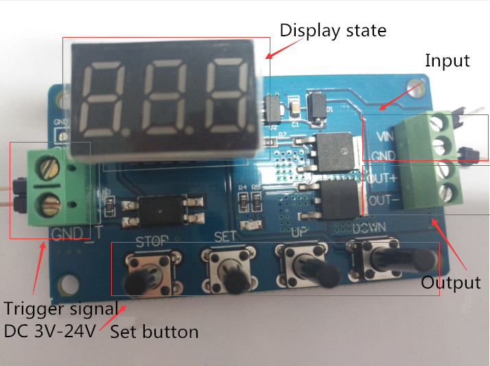
Working voltage: DC5V-DC30V (wide voltage anti-connection protection)
Trigger signal source: high-level trigger DC 3.0V—24V signal ground and system ground to improve the system's anti-interference ability can also short-circuit the ground
Output capacity: DC DC 5V--36V, continuous current 15A at normal temperature, power 400W! Under the condition of auxiliary heat dissipation, the maximum current can reach 30A
Product size: 64mm*35mm*19.3mm
Mounting hole: diameter 3mm
Working temperature: -40 ° C ~ 85 ° C
2.Operating mode
P1 mode: After the signal is triggered, the MOS transistor turns on the OP time and then turns off; in the OP time, the following operation
P1.1: The signal is triggered again.
P1.2: Signal triggers re-timed again
P1.3: The signal triggers reset again, the MOS tube is disconnected, and the timing is stopped.
P-2: Give the trigger signal, after the MOS transistor is disconnected from the CL time, the MOS transistor turns on the OP time. After the timing is completed, the MOS transistor is disconnected.
P3.1: Give the trigger signal, after the MOS transistor turns on the OP time, the MOS tube turns off the CL time, then loops the above action, the signal is given again in the loop, the MOS tube is disconnected, the timing is stopped; the number of cycles (LOP) can be set.
P3.2: No need to trigger signal after power-on, MOS tube turns on OP time, MOS tube disconnects CL time, loops the above action; loop number (LOP) can be set
P-4: Signal hold function If there is a trigger signal, the timing is cleared, the MOS transistor remains on; when the signal disappears, the MOS transistor is disconnected after timing the OP; during the timing, there is a signal and the timing is cleared.
3.Relay enable mode
ON : MOS tube is allowed to conduct during OP conduction time
OFF : MOS tube is disabled, always off
Short press the STOP button on the main interface to switch between ON and OFF. The current state will flash, then return to the main interface. This function is the emergency stop function. One button is used to open and close the MOS tube.
4.Sleep mode (long press the stop button to view the current mode)
C-P sleep mode: within five minutes, without any operation, the digital tube automatically turns off the display, the program runs normally.
O-d normal mode: the digital tube is always on display
Press and hold the STOP button for 2 seconds and then release to switch the C-P and O-d states. The current state will flash and then return to the main interface.
5.Timing range
How to choose the timing range
1).After setting the parameter value in the mode selection interface, press the STOP button to select the timing range.
XXX. Decimal point is in one place, timing range: 1 second to 999 seconds
XX.X decimal point in ten, timing range: 0.1 seconds to 99.9 seconds
X.X.X. The decimal point is fully illuminated, the timing range is from 1 minute to 999 minutes.
2).For example, if you want to set the OP to 3.2 seconds, move the decimal point to ten digits, and the digital tube displays 03.2.
Parameter description: OP on time, CL off time, LOP cycle number 1-999 times, "---" stands for infinite loop.
These parameters are independent of each other, but each mode shares these parameters. For example, when the on-time OP is set to 5 seconds in P1.1, the user wants to switch to the P1.2 mode, then when entering the P1.2 setting corresponding parameters, the OP also It will be 5 seconds.
Displaying 000 on the main interface and pressing the SET button will display OPL, LOP and corresponding time XXX
If only OP in the mode, such as mode P1.1, P1.2, P1.3 time, then short press SET button will only display OP and corresponding time.
If the mode has OP, CL, LOP such as mode P3.1, P3.2 short press SET button will display OP and corresponding time, CL and corresponding time, LOP and corresponding times.
After setting the mode, it is very convenient to easily check the parameters set in the current mode by pressing the SET button on the main interface.
6.How to set parameters
1) First determine the working mode of the MOS tube
According to the working mode of the MOS tube, in the main interface (when the module is powered on, it will flash the current working mode (default P1.1 mode), then enter the main interface "press and hold the SET button for 2 seconds and then release" to enter the mode. Select the interface, press the UP, DOWN button to select the mode to be set P1.1~P-4
2) After selecting the mode to be set (for example, P3.2), press the SET button to set the corresponding parameter. At this time, the parameter to be set will flash OP ON time, CL OFF time, LOP cycle number “---” Represents an infinite loop, adjusts the parameter value through UP and DOWN, supports long press (rapid increase or decrease) and short press (increase or decrease 1 unit); after setting the parameter value, select the decimal point position by short pressing the STOP button. , select the timing range (corresponding time 0.1 seconds ~ 999 minutes); short press the SET button to set the next parameter of the current mode, the process is the same as above.
3) After setting the parameters of the selected mode, press and hold the SET button for 2 seconds to release, the currently set mode will flash, then return to the main interface and set the parameters successfully.
4) Main interface: “000” (no decimal point) is displayed when the MOS tube is not working, and the MOS tube has a decimal point in the working state.
5) Mode selection interface: long press SET button to enter, after setting is completed, long press SET button to exit, return to the main interface
Note:
The module is an active live output, and the voltage at the output (load) is equal to the input voltage DC
The module is an active live output, and the voltage at the output (load) is equal to the input voltage DC
7.Product illustration:
8.Package Included:
1*DDC-432 4 button 3-digit Digital Tube Dual DC5-30V MOS Delay Control Board +Case
Purchasing & Delivery
Before you make your purchase, it’s helpful to know the measurements of the area you plan to place the furniture. You should also measure any doorways and hallways through which the furniture will pass to get to its final destination.Picking up at the store
Shopify Shop requires that all products are properly inspected BEFORE you take it home to insure there are no surprises. Our team is happy to open all packages and will assist in the inspection process. We will then reseal packages for safe transport. We encourage all customers to bring furniture pads or blankets to protect the items during transport as well as rope or tie downs. Shopify Shop will not be responsible for damage that occurs after leaving the store or during transit. It is the purchaser’s responsibility to make sure the correct items are picked up and in good condition.Delivery
Customers are able to pick the next available delivery day that best fits their schedule. However, to route stops as efficiently as possible, Shopify Shop will provide the time frame. Customers will not be able to choose a time. You will be notified in advance of your scheduled time frame. Please make sure that a responsible adult (18 years or older) will be home at that time.In preparation for your delivery, please remove existing furniture, pictures, mirrors, accessories, etc. to prevent damages. Also insure that the area where you would like your furniture placed is clear of any old furniture and any other items that may obstruct the passageway of the delivery team. Shopify Shop will deliver, assemble, and set-up your new furniture purchase and remove all packing materials from your home. Our delivery crews are not permitted to move your existing furniture or other household items. Delivery personnel will attempt to deliver the purchased items in a safe and controlled manner but will not attempt to place furniture if they feel it will result in damage to the product or your home. Delivery personnel are unable to remove doors, hoist furniture or carry furniture up more than 3 flights of stairs. An elevator must be available for deliveries to the 4th floor and above.
Other Customers also buy:
-
 Translation missing: en.products.product.regular_price $5.99{"id":4364187009095,"title":"DDC-432 4 button 3-digit Digital Tube Dual DC5-30V MOS Delay Controller Display","handle":"ddc-432-4-button-3-digit-digital-tube-dual-dc5-30v-mos-delay-controller-display","description":"\u003cdiv\u003e\n\u003cspan\u003e\u003cstrong\u003eDescription:\u003c\/strong\u003e\u003c\/span\u003e\u003cbr\u003e\u003cspan\u003eDual MOS parallel active output, lower internal resistance, larger current, strong power interface, clear and simple, powerful, one-button emergency stop function (STOP button), with reverse connection protection, reverse connection, no burning, power-off memory. Increase Sleep mode, after enabling, no operation within 5 minutes, automatically turn off the display, wake up any button! You can set different OP, CL, LOP parameters, these parameters are independent of each other, save the setting parameters automatically power-down save and other functions, Almost all the needs!\u003c\/span\u003e\n\u003c\/div\u003e\n\u003cdiv\u003e\n\u003cspan\u003e\u003cstrong\u003e1.Product manual\u003c\/strong\u003e\u003c\/span\u003e\u003cbr\u003e\u003cspan\u003eWorking voltage: DC5V-DC30V (wide voltage anti-connection protection)\u003c\/span\u003e\u003cbr\u003e\u003cspan\u003eTrigger signal source: high-level trigger DC 3.0V—24V signal ground and system ground to improve the system's anti-interference ability can also short-circuit the ground\u003c\/span\u003e\u003cbr\u003e\u003cspan\u003eOutput capacity: DC DC 5V--36V, continuous current 15A at normal temperature, power 400W! Under the condition of auxiliary heat dissipation, the maximum current can reach 30A\u003c\/span\u003e\u003cbr\u003e\u003cspan\u003eProduct size: 64mm*35mm*19.3mm\u003c\/span\u003e\u003cbr\u003e\u003cspan\u003eMounting hole: diameter 3mm\u003c\/span\u003e\u003cbr\u003e\u003cspan\u003eWorking temperature: -40 ° C ~ 85 ° C\u003c\/span\u003e\n\u003c\/div\u003e\n\u003cdiv\u003e\n\u003cspan\u003e\u003cstrong\u003e2.Operating mode\u003c\/strong\u003e\u003c\/span\u003e\u003cbr\u003e\u003cspan\u003eP1 mode: After the signal is triggered, the MOS transistor turns on the OP time and then turns off; in the OP time, the following operation\u003c\/span\u003e\u003cbr\u003e\u003cspan\u003eP1.1: The signal is triggered again.\u003c\/span\u003e\u003cbr\u003e\u003cspan\u003eP1.2: Signal triggers re-timed again\u003c\/span\u003e\u003cbr\u003e\u003cspan\u003eP1.3: The signal triggers reset again, the MOS tube is disconnected, and the timing is stopped.\u003c\/span\u003e\u003cbr\u003e\u003cspan\u003eP-2: Give the trigger signal, after the MOS transistor is disconnected from the CL time, the MOS transistor turns on the OP time. After the timing is completed, the MOS transistor is disconnected.\u003c\/span\u003e\u003cbr\u003e\u003cspan\u003eP3.1: Give the trigger signal, after the MOS transistor turns on the OP time, the MOS tube turns off the CL time, then loops the above action, the signal is given again in the loop, the MOS tube is disconnected, the timing is stopped; the number of cycles (LOP) can be set.\u003c\/span\u003e\u003cbr\u003e\u003cspan\u003eP3.2: No need to trigger signal after power-on, MOS tube turns on OP time, MOS tube disconnects CL time, loops the above action; loop number (LOP) can be set\u003c\/span\u003e\u003cbr\u003e\u003cspan\u003eP-4: Signal hold function If there is a trigger signal, the timing is cleared, the MOS transistor remains on; when the signal disappears, the MOS transistor is disconnected after timing the OP; during the timing, there is a signal and the timing is cleared.\u003c\/span\u003e\n\u003c\/div\u003e\n\u003cdiv\u003e\n\u003cspan\u003e\u003cstrong\u003e3.Relay enable mode\u003c\/strong\u003e\u003c\/span\u003e\u003cbr\u003e\u003cspan\u003eON : MOS tube is allowed to conduct during OP conduction time\u003c\/span\u003e\u003cbr\u003e\u003cspan\u003eOFF : MOS tube is disabled, always off\u003c\/span\u003e\u003cbr\u003e\u003cspan\u003eShort press the STOP button on the main interface to switch between ON and OFF. The current state will flash, then return to the main interface. This function is the emergency stop function. One button is used to open and close the MOS tube.\u003c\/span\u003e\n\u003c\/div\u003e\n\u003cdiv\u003e\n\u003cspan\u003e\u003cstrong\u003e4.Sleep mode (long press the stop button to view the current mode)\u003c\/strong\u003e\u003c\/span\u003e\u003cbr\u003e\u003cspan\u003eC-P sleep mode: within five minutes, without any operation, the digital tube automatically turns off the display, the program runs normally.\u003c\/span\u003e\u003cbr\u003e\u003cspan\u003eO-d normal mode: the digital tube is always on display\u003c\/span\u003e\u003cbr\u003e\u003cspan\u003ePress and hold the STOP button for 2 seconds and then release to switch the C-P and O-d states. The current state will flash and then return to the main interface.\u003c\/span\u003e\n\u003c\/div\u003e\n\u003cdiv\u003e\n\u003cspan\u003e\u003cstrong\u003e5.Timing range\u003c\/strong\u003e\u003c\/span\u003e\u003cbr\u003e\u003cspan\u003eHow to choose the timing range\u003c\/span\u003e\u003cbr\u003e\u003cspan\u003e1).After setting the parameter value in the mode selection interface, press the STOP button to select the timing range.\u003c\/span\u003e\u003cbr\u003e\u003cspan\u003eXXX. Decimal point is in one place, timing range: 1 second to 999 seconds\u003c\/span\u003e\u003cbr\u003e\u003cspan\u003eXX.X decimal point in ten, timing range: 0.1 seconds to 99.9 seconds\u003c\/span\u003e\u003cbr\u003e\u003cspan\u003eX.X.X. The decimal point is fully illuminated, the timing range is from 1 minute to 999 minutes.\u003c\/span\u003e\n\u003c\/div\u003e\n\u003cdiv\u003e\n\u003cspan\u003e2).For example, if you want to set the OP to 3.2 seconds, move the decimal point to ten digits, and the digital tube displays 03.2.\u003c\/span\u003e\u003cbr\u003e\u003cspan\u003eParameter description: OP on time, CL off time, LOP cycle number 1-999 times, \"---\" stands for infinite loop.\u003c\/span\u003e\u003cbr\u003e\u003cspan\u003eThese parameters are independent of each other, but each mode shares these parameters. For example, when the on-time OP is set to 5 seconds in P1.1, the user wants to switch to the P1.2 mode, then when entering the P1.2 setting corresponding parameters, the OP also It will be 5 seconds.\u003c\/span\u003e\u003cbr\u003e\u003cspan\u003eDisplaying 000 on the main interface and pressing the SET button will display OPL, LOP and corresponding time XXX\u003c\/span\u003e\u003cbr\u003e\u003cspan\u003eIf only OP in the mode, such as mode P1.1, P1.2, P1.3 time, then short press SET button will only display OP and corresponding time.\u003c\/span\u003e\u003cbr\u003e\u003cspan\u003eIf the mode has OP, CL, LOP such as mode P3.1, P3.2 short press SET button will display OP and corresponding time, CL and corresponding time, LOP and corresponding times.\u003c\/span\u003e\u003cbr\u003e\u003cspan\u003eAfter setting the mode, it is very convenient to easily check the parameters set in the current mode by pressing the SET button on the main interface.\u003c\/span\u003e\n\u003c\/div\u003e\n\u003cdiv\u003e\n\u003cspan\u003e\u003cstrong\u003e6.How to set parameters\u003c\/strong\u003e\u003c\/span\u003e\u003cbr\u003e\u003cspan\u003e1) First determine the working mode of the MOS tube\u003c\/span\u003e\u003cbr\u003e\u003cspan\u003eAccording to the working mode of the MOS tube, in the main interface (when the module is powered on, it will flash the current working mode (default P1.1 mode), then enter the main interface \"press and hold the SET button for 2 seconds and then release\" to enter the mode. Select the interface, press the UP, DOWN button to select the mode to be set P1.1~P-4\u003c\/span\u003e\u003cbr\u003e\u003cspan\u003e2) After selecting the mode to be set (for example, P3.2), press the SET button to set the corresponding parameter. At this time, the parameter to be set will flash OP ON time, CL OFF time, LOP cycle number “---” Represents an infinite loop, adjusts the parameter value through UP and DOWN, supports long press (rapid increase or decrease) and short press (increase or decrease 1 unit); after setting the parameter value, select the decimal point position by short pressing the STOP button. , select the timing range (corresponding time 0.1 seconds ~ 999 minutes); short press the SET button to set the next parameter of the current mode, the process is the same as above.\u003c\/span\u003e\u003cbr\u003e\u003cspan\u003e3) After setting the parameters of the selected mode, press and hold the SET button for 2 seconds to release, the currently set mode will flash, then return to the main interface and set the parameters successfully.\u003c\/span\u003e\u003cbr\u003e\u003cspan\u003e4) Main interface: “000” (no decimal point) is displayed when the MOS tube is not working, and the MOS tube has a decimal point in the working state.\u003c\/span\u003e\u003cbr\u003e\u003cspan\u003e5) Mode selection interface: long press SET button to enter, after setting is completed, long press SET button to exit, return to the main interface\u003c\/span\u003e\n\u003c\/div\u003e\n\u003cdiv\u003e\n\u003cspan\u003e\u003cstrong\u003eNote:\u003c\/strong\u003e\u003c\/span\u003e\u003cbr\u003e\u003cspan\u003e\u003cstrong\u003eThe module is an active live output, and the voltage at the output (load) is equal to the input voltage DC\u003c\/strong\u003e\u003c\/span\u003e\n\u003c\/div\u003e\n\u003cdiv\u003e\u003cspan\u003e\u003cstrong\u003e7.Product illustration:\u003c\/strong\u003e\u003c\/span\u003e\u003c\/div\u003e\n\u003cdiv\u003e\u003cimg src=\"https:\/\/pg-cdn-a2.datacaciques.com\/00\/NDAy\/19\/08\/09\/q596misp0rqvln9v\/afe64143851a91a8.png\"\u003e\u003c\/div\u003e\n\u003cdiv\u003e\n\u003cspan\u003e\u003cstrong\u003e8.Package Included:\u003c\/strong\u003e\u003c\/span\u003e\n\u003cdiv\u003e\u003cspan\u003e1*DDC-432 4 button 3-digit Digital Tube Dual DC5-30V MOS Delay Control Board +Case\u003c\/span\u003e\u003c\/div\u003e\n\u003c\/div\u003e","published_at":"2019-11-20T18:48:21+08:00","created_at":"2019-11-20T19:03:21+08:00","vendor":"diymore","type":"Thermostat","tags":[],"price":799,"price_min":799,"price_max":799,"available":true,"price_varies":false,"compare_at_price":null,"compare_at_price_min":0,"compare_at_price_max":0,"compare_at_price_varies":false,"variants":[{"id":31297845624903,"title":"Default Title","option1":"Default Title","option2":null,"option3":null,"sku":"100038","requires_shipping":true,"taxable":true,"featured_image":null,"available":true,"name":"DDC-432 4 button 3-digit Digital Tube Dual DC5-30V MOS Delay Controller Display","public_title":null,"options":["Default Title"],"price":799,"weight":0,"compare_at_price":null,"inventory_management":null,"barcode":null,"requires_selling_plan":false,"selling_plan_allocations":[],"quantity_rule":{"min":1,"max":null,"increment":1}}],"images":["\/\/www.diymore.cc\/cdn\/shop\/products\/100038_8_537.jpg?v=1588669027","\/\/www.diymore.cc\/cdn\/shop\/products\/100038_1_228.jpg?v=1588669027","\/\/www.diymore.cc\/cdn\/shop\/products\/100038_4_813.jpg?v=1588669027","\/\/www.diymore.cc\/cdn\/shop\/products\/100038_5_479.jpg?v=1588669027","\/\/www.diymore.cc\/cdn\/shop\/products\/100038_7_167.jpg?v=1588669027"],"featured_image":"\/\/www.diymore.cc\/cdn\/shop\/products\/100038_8_537.jpg?v=1588669027","options":["Title"],"media":[{"alt":"Ddc-432 4 Button 3-Digit Digital Tube Dual Dc5-30V Mos Delay Controller Display Thermostat","id":6679915167815,"position":1,"preview_image":{"aspect_ratio":1.0,"height":1000,"width":1000,"src":"\/\/www.diymore.cc\/cdn\/shop\/products\/100038_8_537.jpg?v=1588669027"},"aspect_ratio":1.0,"height":1000,"media_type":"image","src":"\/\/www.diymore.cc\/cdn\/shop\/products\/100038_8_537.jpg?v=1588669027","width":1000},{"alt":"Ddc-432 4 Button 3-Digit Digital Tube Dual Dc5-30V Mos Delay Controller Display Thermostat","id":6679915233351,"position":2,"preview_image":{"aspect_ratio":1.0,"height":1000,"width":1000,"src":"\/\/www.diymore.cc\/cdn\/shop\/products\/100038_1_228.jpg?v=1588669027"},"aspect_ratio":1.0,"height":1000,"media_type":"image","src":"\/\/www.diymore.cc\/cdn\/shop\/products\/100038_1_228.jpg?v=1588669027","width":1000},{"alt":"Ddc-432 4 Button 3-Digit Digital Tube Dual Dc5-30V Mos Delay Controller Display Thermostat","id":6679915397191,"position":3,"preview_image":{"aspect_ratio":1.0,"height":1000,"width":1000,"src":"\/\/www.diymore.cc\/cdn\/shop\/products\/100038_4_813.jpg?v=1588669027"},"aspect_ratio":1.0,"height":1000,"media_type":"image","src":"\/\/www.diymore.cc\/cdn\/shop\/products\/100038_4_813.jpg?v=1588669027","width":1000},{"alt":"Ddc-432 4 Button 3-Digit Digital Tube Dual Dc5-30V Mos Delay Controller Display Thermostat","id":6679915561031,"position":4,"preview_image":{"aspect_ratio":1.0,"height":1000,"width":1000,"src":"\/\/www.diymore.cc\/cdn\/shop\/products\/100038_5_479.jpg?v=1588669027"},"aspect_ratio":1.0,"height":1000,"media_type":"image","src":"\/\/www.diymore.cc\/cdn\/shop\/products\/100038_5_479.jpg?v=1588669027","width":1000},{"alt":"Ddc-432 4 Button 3-Digit Digital Tube Dual Dc5-30V Mos Delay Controller Display Thermostat","id":6679915626567,"position":5,"preview_image":{"aspect_ratio":1.0,"height":1000,"width":1000,"src":"\/\/www.diymore.cc\/cdn\/shop\/products\/100038_7_167.jpg?v=1588669027"},"aspect_ratio":1.0,"height":1000,"media_type":"image","src":"\/\/www.diymore.cc\/cdn\/shop\/products\/100038_7_167.jpg?v=1588669027","width":1000}],"requires_selling_plan":false,"selling_plan_groups":[],"content":"\u003cdiv\u003e\n\u003cspan\u003e\u003cstrong\u003eDescription:\u003c\/strong\u003e\u003c\/span\u003e\u003cbr\u003e\u003cspan\u003eDual MOS parallel active output, lower internal resistance, larger current, strong power interface, clear and simple, powerful, one-button emergency stop function (STOP button), with reverse connection protection, reverse connection, no burning, power-off memory. Increase Sleep mode, after enabling, no operation within 5 minutes, automatically turn off the display, wake up any button! You can set different OP, CL, LOP parameters, these parameters are independent of each other, save the setting parameters automatically power-down save and other functions, Almost all the needs!\u003c\/span\u003e\n\u003c\/div\u003e\n\u003cdiv\u003e\n\u003cspan\u003e\u003cstrong\u003e1.Product manual\u003c\/strong\u003e\u003c\/span\u003e\u003cbr\u003e\u003cspan\u003eWorking voltage: DC5V-DC30V (wide voltage anti-connection protection)\u003c\/span\u003e\u003cbr\u003e\u003cspan\u003eTrigger signal source: high-level trigger DC 3.0V—24V signal ground and system ground to improve the system's anti-interference ability can also short-circuit the ground\u003c\/span\u003e\u003cbr\u003e\u003cspan\u003eOutput capacity: DC DC 5V--36V, continuous current 15A at normal temperature, power 400W! Under the condition of auxiliary heat dissipation, the maximum current can reach 30A\u003c\/span\u003e\u003cbr\u003e\u003cspan\u003eProduct size: 64mm*35mm*19.3mm\u003c\/span\u003e\u003cbr\u003e\u003cspan\u003eMounting hole: diameter 3mm\u003c\/span\u003e\u003cbr\u003e\u003cspan\u003eWorking temperature: -40 ° C ~ 85 ° C\u003c\/span\u003e\n\u003c\/div\u003e\n\u003cdiv\u003e\n\u003cspan\u003e\u003cstrong\u003e2.Operating mode\u003c\/strong\u003e\u003c\/span\u003e\u003cbr\u003e\u003cspan\u003eP1 mode: After the signal is triggered, the MOS transistor turns on the OP time and then turns off; in the OP time, the following operation\u003c\/span\u003e\u003cbr\u003e\u003cspan\u003eP1.1: The signal is triggered again.\u003c\/span\u003e\u003cbr\u003e\u003cspan\u003eP1.2: Signal triggers re-timed again\u003c\/span\u003e\u003cbr\u003e\u003cspan\u003eP1.3: The signal triggers reset again, the MOS tube is disconnected, and the timing is stopped.\u003c\/span\u003e\u003cbr\u003e\u003cspan\u003eP-2: Give the trigger signal, after the MOS transistor is disconnected from the CL time, the MOS transistor turns on the OP time. After the timing is completed, the MOS transistor is disconnected.\u003c\/span\u003e\u003cbr\u003e\u003cspan\u003eP3.1: Give the trigger signal, after the MOS transistor turns on the OP time, the MOS tube turns off the CL time, then loops the above action, the signal is given again in the loop, the MOS tube is disconnected, the timing is stopped; the number of cycles (LOP) can be set.\u003c\/span\u003e\u003cbr\u003e\u003cspan\u003eP3.2: No need to trigger signal after power-on, MOS tube turns on OP time, MOS tube disconnects CL time, loops the above action; loop number (LOP) can be set\u003c\/span\u003e\u003cbr\u003e\u003cspan\u003eP-4: Signal hold function If there is a trigger signal, the timing is cleared, the MOS transistor remains on; when the signal disappears, the MOS transistor is disconnected after timing the OP; during the timing, there is a signal and the timing is cleared.\u003c\/span\u003e\n\u003c\/div\u003e\n\u003cdiv\u003e\n\u003cspan\u003e\u003cstrong\u003e3.Relay enable mode\u003c\/strong\u003e\u003c\/span\u003e\u003cbr\u003e\u003cspan\u003eON : MOS tube is allowed to conduct during OP conduction time\u003c\/span\u003e\u003cbr\u003e\u003cspan\u003eOFF : MOS tube is disabled, always off\u003c\/span\u003e\u003cbr\u003e\u003cspan\u003eShort press the STOP button on the main interface to switch between ON and OFF. The current state will flash, then return to the main interface. This function is the emergency stop function. One button is used to open and close the MOS tube.\u003c\/span\u003e\n\u003c\/div\u003e\n\u003cdiv\u003e\n\u003cspan\u003e\u003cstrong\u003e4.Sleep mode (long press the stop button to view the current mode)\u003c\/strong\u003e\u003c\/span\u003e\u003cbr\u003e\u003cspan\u003eC-P sleep mode: within five minutes, without any operation, the digital tube automatically turns off the display, the program runs normally.\u003c\/span\u003e\u003cbr\u003e\u003cspan\u003eO-d normal mode: the digital tube is always on display\u003c\/span\u003e\u003cbr\u003e\u003cspan\u003ePress and hold the STOP button for 2 seconds and then release to switch the C-P and O-d states. The current state will flash and then return to the main interface.\u003c\/span\u003e\n\u003c\/div\u003e\n\u003cdiv\u003e\n\u003cspan\u003e\u003cstrong\u003e5.Timing range\u003c\/strong\u003e\u003c\/span\u003e\u003cbr\u003e\u003cspan\u003eHow to choose the timing range\u003c\/span\u003e\u003cbr\u003e\u003cspan\u003e1).After setting the parameter value in the mode selection interface, press the STOP button to select the timing range.\u003c\/span\u003e\u003cbr\u003e\u003cspan\u003eXXX. Decimal point is in one place, timing range: 1 second to 999 seconds\u003c\/span\u003e\u003cbr\u003e\u003cspan\u003eXX.X decimal point in ten, timing range: 0.1 seconds to 99.9 seconds\u003c\/span\u003e\u003cbr\u003e\u003cspan\u003eX.X.X. The decimal point is fully illuminated, the timing range is from 1 minute to 999 minutes.\u003c\/span\u003e\n\u003c\/div\u003e\n\u003cdiv\u003e\n\u003cspan\u003e2).For example, if you want to set the OP to 3.2 seconds, move the decimal point to ten digits, and the digital tube displays 03.2.\u003c\/span\u003e\u003cbr\u003e\u003cspan\u003eParameter description: OP on time, CL off time, LOP cycle number 1-999 times, \"---\" stands for infinite loop.\u003c\/span\u003e\u003cbr\u003e\u003cspan\u003eThese parameters are independent of each other, but each mode shares these parameters. For example, when the on-time OP is set to 5 seconds in P1.1, the user wants to switch to the P1.2 mode, then when entering the P1.2 setting corresponding parameters, the OP also It will be 5 seconds.\u003c\/span\u003e\u003cbr\u003e\u003cspan\u003eDisplaying 000 on the main interface and pressing the SET button will display OPL, LOP and corresponding time XXX\u003c\/span\u003e\u003cbr\u003e\u003cspan\u003eIf only OP in the mode, such as mode P1.1, P1.2, P1.3 time, then short press SET button will only display OP and corresponding time.\u003c\/span\u003e\u003cbr\u003e\u003cspan\u003eIf the mode has OP, CL, LOP such as mode P3.1, P3.2 short press SET button will display OP and corresponding time, CL and corresponding time, LOP and corresponding times.\u003c\/span\u003e\u003cbr\u003e\u003cspan\u003eAfter setting the mode, it is very convenient to easily check the parameters set in the current mode by pressing the SET button on the main interface.\u003c\/span\u003e\n\u003c\/div\u003e\n\u003cdiv\u003e\n\u003cspan\u003e\u003cstrong\u003e6.How to set parameters\u003c\/strong\u003e\u003c\/span\u003e\u003cbr\u003e\u003cspan\u003e1) First determine the working mode of the MOS tube\u003c\/span\u003e\u003cbr\u003e\u003cspan\u003eAccording to the working mode of the MOS tube, in the main interface (when the module is powered on, it will flash the current working mode (default P1.1 mode), then enter the main interface \"press and hold the SET button for 2 seconds and then release\" to enter the mode. Select the interface, press the UP, DOWN button to select the mode to be set P1.1~P-4\u003c\/span\u003e\u003cbr\u003e\u003cspan\u003e2) After selecting the mode to be set (for example, P3.2), press the SET button to set the corresponding parameter. At this time, the parameter to be set will flash OP ON time, CL OFF time, LOP cycle number “---” Represents an infinite loop, adjusts the parameter value through UP and DOWN, supports long press (rapid increase or decrease) and short press (increase or decrease 1 unit); after setting the parameter value, select the decimal point position by short pressing the STOP button. , select the timing range (corresponding time 0.1 seconds ~ 999 minutes); short press the SET button to set the next parameter of the current mode, the process is the same as above.\u003c\/span\u003e\u003cbr\u003e\u003cspan\u003e3) After setting the parameters of the selected mode, press and hold the SET button for 2 seconds to release, the currently set mode will flash, then return to the main interface and set the parameters successfully.\u003c\/span\u003e\u003cbr\u003e\u003cspan\u003e4) Main interface: “000” (no decimal point) is displayed when the MOS tube is not working, and the MOS tube has a decimal point in the working state.\u003c\/span\u003e\u003cbr\u003e\u003cspan\u003e5) Mode selection interface: long press SET button to enter, after setting is completed, long press SET button to exit, return to the main interface\u003c\/span\u003e\n\u003c\/div\u003e\n\u003cdiv\u003e\n\u003cspan\u003e\u003cstrong\u003eNote:\u003c\/strong\u003e\u003c\/span\u003e\u003cbr\u003e\u003cspan\u003e\u003cstrong\u003eThe module is an active live output, and the voltage at the output (load) is equal to the input voltage DC\u003c\/strong\u003e\u003c\/span\u003e\n\u003c\/div\u003e\n\u003cdiv\u003e\u003cspan\u003e\u003cstrong\u003e7.Product illustration:\u003c\/strong\u003e\u003c\/span\u003e\u003c\/div\u003e\n\u003cdiv\u003e\u003cimg src=\"https:\/\/pg-cdn-a2.datacaciques.com\/00\/NDAy\/19\/08\/09\/q596misp0rqvln9v\/afe64143851a91a8.png\"\u003e\u003c\/div\u003e\n\u003cdiv\u003e\n\u003cspan\u003e\u003cstrong\u003e8.Package Included:\u003c\/strong\u003e\u003c\/span\u003e\n\u003cdiv\u003e\u003cspan\u003e1*DDC-432 4 button 3-digit Digital Tube Dual DC5-30V MOS Delay Control Board +Case\u003c\/span\u003e\u003c\/div\u003e\n\u003c\/div\u003e"}
 -
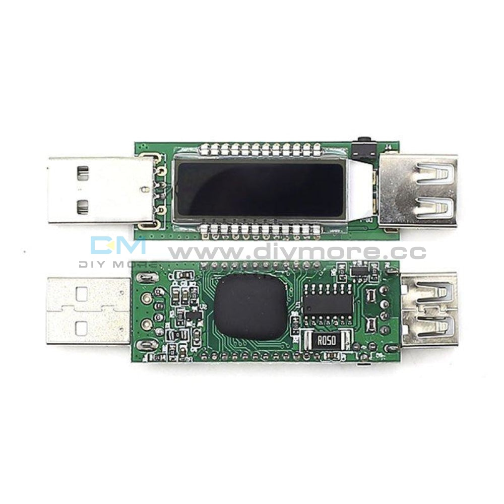
 Translation missing: en.products.product.regular_price $7.99{"id":4364187009095,"title":"DDC-432 4 button 3-digit Digital Tube Dual DC5-30V MOS Delay Controller Display","handle":"ddc-432-4-button-3-digit-digital-tube-dual-dc5-30v-mos-delay-controller-display","description":"\u003cdiv\u003e\n\u003cspan\u003e\u003cstrong\u003eDescription:\u003c\/strong\u003e\u003c\/span\u003e\u003cbr\u003e\u003cspan\u003eDual MOS parallel active output, lower internal resistance, larger current, strong power interface, clear and simple, powerful, one-button emergency stop function (STOP button), with reverse connection protection, reverse connection, no burning, power-off memory. Increase Sleep mode, after enabling, no operation within 5 minutes, automatically turn off the display, wake up any button! You can set different OP, CL, LOP parameters, these parameters are independent of each other, save the setting parameters automatically power-down save and other functions, Almost all the needs!\u003c\/span\u003e\n\u003c\/div\u003e\n\u003cdiv\u003e\n\u003cspan\u003e\u003cstrong\u003e1.Product manual\u003c\/strong\u003e\u003c\/span\u003e\u003cbr\u003e\u003cspan\u003eWorking voltage: DC5V-DC30V (wide voltage anti-connection protection)\u003c\/span\u003e\u003cbr\u003e\u003cspan\u003eTrigger signal source: high-level trigger DC 3.0V—24V signal ground and system ground to improve the system's anti-interference ability can also short-circuit the ground\u003c\/span\u003e\u003cbr\u003e\u003cspan\u003eOutput capacity: DC DC 5V--36V, continuous current 15A at normal temperature, power 400W! Under the condition of auxiliary heat dissipation, the maximum current can reach 30A\u003c\/span\u003e\u003cbr\u003e\u003cspan\u003eProduct size: 64mm*35mm*19.3mm\u003c\/span\u003e\u003cbr\u003e\u003cspan\u003eMounting hole: diameter 3mm\u003c\/span\u003e\u003cbr\u003e\u003cspan\u003eWorking temperature: -40 ° C ~ 85 ° C\u003c\/span\u003e\n\u003c\/div\u003e\n\u003cdiv\u003e\n\u003cspan\u003e\u003cstrong\u003e2.Operating mode\u003c\/strong\u003e\u003c\/span\u003e\u003cbr\u003e\u003cspan\u003eP1 mode: After the signal is triggered, the MOS transistor turns on the OP time and then turns off; in the OP time, the following operation\u003c\/span\u003e\u003cbr\u003e\u003cspan\u003eP1.1: The signal is triggered again.\u003c\/span\u003e\u003cbr\u003e\u003cspan\u003eP1.2: Signal triggers re-timed again\u003c\/span\u003e\u003cbr\u003e\u003cspan\u003eP1.3: The signal triggers reset again, the MOS tube is disconnected, and the timing is stopped.\u003c\/span\u003e\u003cbr\u003e\u003cspan\u003eP-2: Give the trigger signal, after the MOS transistor is disconnected from the CL time, the MOS transistor turns on the OP time. After the timing is completed, the MOS transistor is disconnected.\u003c\/span\u003e\u003cbr\u003e\u003cspan\u003eP3.1: Give the trigger signal, after the MOS transistor turns on the OP time, the MOS tube turns off the CL time, then loops the above action, the signal is given again in the loop, the MOS tube is disconnected, the timing is stopped; the number of cycles (LOP) can be set.\u003c\/span\u003e\u003cbr\u003e\u003cspan\u003eP3.2: No need to trigger signal after power-on, MOS tube turns on OP time, MOS tube disconnects CL time, loops the above action; loop number (LOP) can be set\u003c\/span\u003e\u003cbr\u003e\u003cspan\u003eP-4: Signal hold function If there is a trigger signal, the timing is cleared, the MOS transistor remains on; when the signal disappears, the MOS transistor is disconnected after timing the OP; during the timing, there is a signal and the timing is cleared.\u003c\/span\u003e\n\u003c\/div\u003e\n\u003cdiv\u003e\n\u003cspan\u003e\u003cstrong\u003e3.Relay enable mode\u003c\/strong\u003e\u003c\/span\u003e\u003cbr\u003e\u003cspan\u003eON : MOS tube is allowed to conduct during OP conduction time\u003c\/span\u003e\u003cbr\u003e\u003cspan\u003eOFF : MOS tube is disabled, always off\u003c\/span\u003e\u003cbr\u003e\u003cspan\u003eShort press the STOP button on the main interface to switch between ON and OFF. The current state will flash, then return to the main interface. This function is the emergency stop function. One button is used to open and close the MOS tube.\u003c\/span\u003e\n\u003c\/div\u003e\n\u003cdiv\u003e\n\u003cspan\u003e\u003cstrong\u003e4.Sleep mode (long press the stop button to view the current mode)\u003c\/strong\u003e\u003c\/span\u003e\u003cbr\u003e\u003cspan\u003eC-P sleep mode: within five minutes, without any operation, the digital tube automatically turns off the display, the program runs normally.\u003c\/span\u003e\u003cbr\u003e\u003cspan\u003eO-d normal mode: the digital tube is always on display\u003c\/span\u003e\u003cbr\u003e\u003cspan\u003ePress and hold the STOP button for 2 seconds and then release to switch the C-P and O-d states. The current state will flash and then return to the main interface.\u003c\/span\u003e\n\u003c\/div\u003e\n\u003cdiv\u003e\n\u003cspan\u003e\u003cstrong\u003e5.Timing range\u003c\/strong\u003e\u003c\/span\u003e\u003cbr\u003e\u003cspan\u003eHow to choose the timing range\u003c\/span\u003e\u003cbr\u003e\u003cspan\u003e1).After setting the parameter value in the mode selection interface, press the STOP button to select the timing range.\u003c\/span\u003e\u003cbr\u003e\u003cspan\u003eXXX. Decimal point is in one place, timing range: 1 second to 999 seconds\u003c\/span\u003e\u003cbr\u003e\u003cspan\u003eXX.X decimal point in ten, timing range: 0.1 seconds to 99.9 seconds\u003c\/span\u003e\u003cbr\u003e\u003cspan\u003eX.X.X. The decimal point is fully illuminated, the timing range is from 1 minute to 999 minutes.\u003c\/span\u003e\n\u003c\/div\u003e\n\u003cdiv\u003e\n\u003cspan\u003e2).For example, if you want to set the OP to 3.2 seconds, move the decimal point to ten digits, and the digital tube displays 03.2.\u003c\/span\u003e\u003cbr\u003e\u003cspan\u003eParameter description: OP on time, CL off time, LOP cycle number 1-999 times, \"---\" stands for infinite loop.\u003c\/span\u003e\u003cbr\u003e\u003cspan\u003eThese parameters are independent of each other, but each mode shares these parameters. For example, when the on-time OP is set to 5 seconds in P1.1, the user wants to switch to the P1.2 mode, then when entering the P1.2 setting corresponding parameters, the OP also It will be 5 seconds.\u003c\/span\u003e\u003cbr\u003e\u003cspan\u003eDisplaying 000 on the main interface and pressing the SET button will display OPL, LOP and corresponding time XXX\u003c\/span\u003e\u003cbr\u003e\u003cspan\u003eIf only OP in the mode, such as mode P1.1, P1.2, P1.3 time, then short press SET button will only display OP and corresponding time.\u003c\/span\u003e\u003cbr\u003e\u003cspan\u003eIf the mode has OP, CL, LOP such as mode P3.1, P3.2 short press SET button will display OP and corresponding time, CL and corresponding time, LOP and corresponding times.\u003c\/span\u003e\u003cbr\u003e\u003cspan\u003eAfter setting the mode, it is very convenient to easily check the parameters set in the current mode by pressing the SET button on the main interface.\u003c\/span\u003e\n\u003c\/div\u003e\n\u003cdiv\u003e\n\u003cspan\u003e\u003cstrong\u003e6.How to set parameters\u003c\/strong\u003e\u003c\/span\u003e\u003cbr\u003e\u003cspan\u003e1) First determine the working mode of the MOS tube\u003c\/span\u003e\u003cbr\u003e\u003cspan\u003eAccording to the working mode of the MOS tube, in the main interface (when the module is powered on, it will flash the current working mode (default P1.1 mode), then enter the main interface \"press and hold the SET button for 2 seconds and then release\" to enter the mode. Select the interface, press the UP, DOWN button to select the mode to be set P1.1~P-4\u003c\/span\u003e\u003cbr\u003e\u003cspan\u003e2) After selecting the mode to be set (for example, P3.2), press the SET button to set the corresponding parameter. At this time, the parameter to be set will flash OP ON time, CL OFF time, LOP cycle number “---” Represents an infinite loop, adjusts the parameter value through UP and DOWN, supports long press (rapid increase or decrease) and short press (increase or decrease 1 unit); after setting the parameter value, select the decimal point position by short pressing the STOP button. , select the timing range (corresponding time 0.1 seconds ~ 999 minutes); short press the SET button to set the next parameter of the current mode, the process is the same as above.\u003c\/span\u003e\u003cbr\u003e\u003cspan\u003e3) After setting the parameters of the selected mode, press and hold the SET button for 2 seconds to release, the currently set mode will flash, then return to the main interface and set the parameters successfully.\u003c\/span\u003e\u003cbr\u003e\u003cspan\u003e4) Main interface: “000” (no decimal point) is displayed when the MOS tube is not working, and the MOS tube has a decimal point in the working state.\u003c\/span\u003e\u003cbr\u003e\u003cspan\u003e5) Mode selection interface: long press SET button to enter, after setting is completed, long press SET button to exit, return to the main interface\u003c\/span\u003e\n\u003c\/div\u003e\n\u003cdiv\u003e\n\u003cspan\u003e\u003cstrong\u003eNote:\u003c\/strong\u003e\u003c\/span\u003e\u003cbr\u003e\u003cspan\u003e\u003cstrong\u003eThe module is an active live output, and the voltage at the output (load) is equal to the input voltage DC\u003c\/strong\u003e\u003c\/span\u003e\n\u003c\/div\u003e\n\u003cdiv\u003e\u003cspan\u003e\u003cstrong\u003e7.Product illustration:\u003c\/strong\u003e\u003c\/span\u003e\u003c\/div\u003e\n\u003cdiv\u003e\u003cimg src=\"https:\/\/pg-cdn-a2.datacaciques.com\/00\/NDAy\/19\/08\/09\/q596misp0rqvln9v\/afe64143851a91a8.png\"\u003e\u003c\/div\u003e\n\u003cdiv\u003e\n\u003cspan\u003e\u003cstrong\u003e8.Package Included:\u003c\/strong\u003e\u003c\/span\u003e\n\u003cdiv\u003e\u003cspan\u003e1*DDC-432 4 button 3-digit Digital Tube Dual DC5-30V MOS Delay Control Board +Case\u003c\/span\u003e\u003c\/div\u003e\n\u003c\/div\u003e","published_at":"2019-11-20T18:48:21+08:00","created_at":"2019-11-20T19:03:21+08:00","vendor":"diymore","type":"Thermostat","tags":[],"price":799,"price_min":799,"price_max":799,"available":true,"price_varies":false,"compare_at_price":null,"compare_at_price_min":0,"compare_at_price_max":0,"compare_at_price_varies":false,"variants":[{"id":31297845624903,"title":"Default Title","option1":"Default Title","option2":null,"option3":null,"sku":"100038","requires_shipping":true,"taxable":true,"featured_image":null,"available":true,"name":"DDC-432 4 button 3-digit Digital Tube Dual DC5-30V MOS Delay Controller Display","public_title":null,"options":["Default Title"],"price":799,"weight":0,"compare_at_price":null,"inventory_management":null,"barcode":null,"requires_selling_plan":false,"selling_plan_allocations":[],"quantity_rule":{"min":1,"max":null,"increment":1}}],"images":["\/\/www.diymore.cc\/cdn\/shop\/products\/100038_8_537.jpg?v=1588669027","\/\/www.diymore.cc\/cdn\/shop\/products\/100038_1_228.jpg?v=1588669027","\/\/www.diymore.cc\/cdn\/shop\/products\/100038_4_813.jpg?v=1588669027","\/\/www.diymore.cc\/cdn\/shop\/products\/100038_5_479.jpg?v=1588669027","\/\/www.diymore.cc\/cdn\/shop\/products\/100038_7_167.jpg?v=1588669027"],"featured_image":"\/\/www.diymore.cc\/cdn\/shop\/products\/100038_8_537.jpg?v=1588669027","options":["Title"],"media":[{"alt":"Ddc-432 4 Button 3-Digit Digital Tube Dual Dc5-30V Mos Delay Controller Display Thermostat","id":6679915167815,"position":1,"preview_image":{"aspect_ratio":1.0,"height":1000,"width":1000,"src":"\/\/www.diymore.cc\/cdn\/shop\/products\/100038_8_537.jpg?v=1588669027"},"aspect_ratio":1.0,"height":1000,"media_type":"image","src":"\/\/www.diymore.cc\/cdn\/shop\/products\/100038_8_537.jpg?v=1588669027","width":1000},{"alt":"Ddc-432 4 Button 3-Digit Digital Tube Dual Dc5-30V Mos Delay Controller Display Thermostat","id":6679915233351,"position":2,"preview_image":{"aspect_ratio":1.0,"height":1000,"width":1000,"src":"\/\/www.diymore.cc\/cdn\/shop\/products\/100038_1_228.jpg?v=1588669027"},"aspect_ratio":1.0,"height":1000,"media_type":"image","src":"\/\/www.diymore.cc\/cdn\/shop\/products\/100038_1_228.jpg?v=1588669027","width":1000},{"alt":"Ddc-432 4 Button 3-Digit Digital Tube Dual Dc5-30V Mos Delay Controller Display Thermostat","id":6679915397191,"position":3,"preview_image":{"aspect_ratio":1.0,"height":1000,"width":1000,"src":"\/\/www.diymore.cc\/cdn\/shop\/products\/100038_4_813.jpg?v=1588669027"},"aspect_ratio":1.0,"height":1000,"media_type":"image","src":"\/\/www.diymore.cc\/cdn\/shop\/products\/100038_4_813.jpg?v=1588669027","width":1000},{"alt":"Ddc-432 4 Button 3-Digit Digital Tube Dual Dc5-30V Mos Delay Controller Display Thermostat","id":6679915561031,"position":4,"preview_image":{"aspect_ratio":1.0,"height":1000,"width":1000,"src":"\/\/www.diymore.cc\/cdn\/shop\/products\/100038_5_479.jpg?v=1588669027"},"aspect_ratio":1.0,"height":1000,"media_type":"image","src":"\/\/www.diymore.cc\/cdn\/shop\/products\/100038_5_479.jpg?v=1588669027","width":1000},{"alt":"Ddc-432 4 Button 3-Digit Digital Tube Dual Dc5-30V Mos Delay Controller Display Thermostat","id":6679915626567,"position":5,"preview_image":{"aspect_ratio":1.0,"height":1000,"width":1000,"src":"\/\/www.diymore.cc\/cdn\/shop\/products\/100038_7_167.jpg?v=1588669027"},"aspect_ratio":1.0,"height":1000,"media_type":"image","src":"\/\/www.diymore.cc\/cdn\/shop\/products\/100038_7_167.jpg?v=1588669027","width":1000}],"requires_selling_plan":false,"selling_plan_groups":[],"content":"\u003cdiv\u003e\n\u003cspan\u003e\u003cstrong\u003eDescription:\u003c\/strong\u003e\u003c\/span\u003e\u003cbr\u003e\u003cspan\u003eDual MOS parallel active output, lower internal resistance, larger current, strong power interface, clear and simple, powerful, one-button emergency stop function (STOP button), with reverse connection protection, reverse connection, no burning, power-off memory. Increase Sleep mode, after enabling, no operation within 5 minutes, automatically turn off the display, wake up any button! You can set different OP, CL, LOP parameters, these parameters are independent of each other, save the setting parameters automatically power-down save and other functions, Almost all the needs!\u003c\/span\u003e\n\u003c\/div\u003e\n\u003cdiv\u003e\n\u003cspan\u003e\u003cstrong\u003e1.Product manual\u003c\/strong\u003e\u003c\/span\u003e\u003cbr\u003e\u003cspan\u003eWorking voltage: DC5V-DC30V (wide voltage anti-connection protection)\u003c\/span\u003e\u003cbr\u003e\u003cspan\u003eTrigger signal source: high-level trigger DC 3.0V—24V signal ground and system ground to improve the system's anti-interference ability can also short-circuit the ground\u003c\/span\u003e\u003cbr\u003e\u003cspan\u003eOutput capacity: DC DC 5V--36V, continuous current 15A at normal temperature, power 400W! Under the condition of auxiliary heat dissipation, the maximum current can reach 30A\u003c\/span\u003e\u003cbr\u003e\u003cspan\u003eProduct size: 64mm*35mm*19.3mm\u003c\/span\u003e\u003cbr\u003e\u003cspan\u003eMounting hole: diameter 3mm\u003c\/span\u003e\u003cbr\u003e\u003cspan\u003eWorking temperature: -40 ° C ~ 85 ° C\u003c\/span\u003e\n\u003c\/div\u003e\n\u003cdiv\u003e\n\u003cspan\u003e\u003cstrong\u003e2.Operating mode\u003c\/strong\u003e\u003c\/span\u003e\u003cbr\u003e\u003cspan\u003eP1 mode: After the signal is triggered, the MOS transistor turns on the OP time and then turns off; in the OP time, the following operation\u003c\/span\u003e\u003cbr\u003e\u003cspan\u003eP1.1: The signal is triggered again.\u003c\/span\u003e\u003cbr\u003e\u003cspan\u003eP1.2: Signal triggers re-timed again\u003c\/span\u003e\u003cbr\u003e\u003cspan\u003eP1.3: The signal triggers reset again, the MOS tube is disconnected, and the timing is stopped.\u003c\/span\u003e\u003cbr\u003e\u003cspan\u003eP-2: Give the trigger signal, after the MOS transistor is disconnected from the CL time, the MOS transistor turns on the OP time. After the timing is completed, the MOS transistor is disconnected.\u003c\/span\u003e\u003cbr\u003e\u003cspan\u003eP3.1: Give the trigger signal, after the MOS transistor turns on the OP time, the MOS tube turns off the CL time, then loops the above action, the signal is given again in the loop, the MOS tube is disconnected, the timing is stopped; the number of cycles (LOP) can be set.\u003c\/span\u003e\u003cbr\u003e\u003cspan\u003eP3.2: No need to trigger signal after power-on, MOS tube turns on OP time, MOS tube disconnects CL time, loops the above action; loop number (LOP) can be set\u003c\/span\u003e\u003cbr\u003e\u003cspan\u003eP-4: Signal hold function If there is a trigger signal, the timing is cleared, the MOS transistor remains on; when the signal disappears, the MOS transistor is disconnected after timing the OP; during the timing, there is a signal and the timing is cleared.\u003c\/span\u003e\n\u003c\/div\u003e\n\u003cdiv\u003e\n\u003cspan\u003e\u003cstrong\u003e3.Relay enable mode\u003c\/strong\u003e\u003c\/span\u003e\u003cbr\u003e\u003cspan\u003eON : MOS tube is allowed to conduct during OP conduction time\u003c\/span\u003e\u003cbr\u003e\u003cspan\u003eOFF : MOS tube is disabled, always off\u003c\/span\u003e\u003cbr\u003e\u003cspan\u003eShort press the STOP button on the main interface to switch between ON and OFF. The current state will flash, then return to the main interface. This function is the emergency stop function. One button is used to open and close the MOS tube.\u003c\/span\u003e\n\u003c\/div\u003e\n\u003cdiv\u003e\n\u003cspan\u003e\u003cstrong\u003e4.Sleep mode (long press the stop button to view the current mode)\u003c\/strong\u003e\u003c\/span\u003e\u003cbr\u003e\u003cspan\u003eC-P sleep mode: within five minutes, without any operation, the digital tube automatically turns off the display, the program runs normally.\u003c\/span\u003e\u003cbr\u003e\u003cspan\u003eO-d normal mode: the digital tube is always on display\u003c\/span\u003e\u003cbr\u003e\u003cspan\u003ePress and hold the STOP button for 2 seconds and then release to switch the C-P and O-d states. The current state will flash and then return to the main interface.\u003c\/span\u003e\n\u003c\/div\u003e\n\u003cdiv\u003e\n\u003cspan\u003e\u003cstrong\u003e5.Timing range\u003c\/strong\u003e\u003c\/span\u003e\u003cbr\u003e\u003cspan\u003eHow to choose the timing range\u003c\/span\u003e\u003cbr\u003e\u003cspan\u003e1).After setting the parameter value in the mode selection interface, press the STOP button to select the timing range.\u003c\/span\u003e\u003cbr\u003e\u003cspan\u003eXXX. Decimal point is in one place, timing range: 1 second to 999 seconds\u003c\/span\u003e\u003cbr\u003e\u003cspan\u003eXX.X decimal point in ten, timing range: 0.1 seconds to 99.9 seconds\u003c\/span\u003e\u003cbr\u003e\u003cspan\u003eX.X.X. The decimal point is fully illuminated, the timing range is from 1 minute to 999 minutes.\u003c\/span\u003e\n\u003c\/div\u003e\n\u003cdiv\u003e\n\u003cspan\u003e2).For example, if you want to set the OP to 3.2 seconds, move the decimal point to ten digits, and the digital tube displays 03.2.\u003c\/span\u003e\u003cbr\u003e\u003cspan\u003eParameter description: OP on time, CL off time, LOP cycle number 1-999 times, \"---\" stands for infinite loop.\u003c\/span\u003e\u003cbr\u003e\u003cspan\u003eThese parameters are independent of each other, but each mode shares these parameters. For example, when the on-time OP is set to 5 seconds in P1.1, the user wants to switch to the P1.2 mode, then when entering the P1.2 setting corresponding parameters, the OP also It will be 5 seconds.\u003c\/span\u003e\u003cbr\u003e\u003cspan\u003eDisplaying 000 on the main interface and pressing the SET button will display OPL, LOP and corresponding time XXX\u003c\/span\u003e\u003cbr\u003e\u003cspan\u003eIf only OP in the mode, such as mode P1.1, P1.2, P1.3 time, then short press SET button will only display OP and corresponding time.\u003c\/span\u003e\u003cbr\u003e\u003cspan\u003eIf the mode has OP, CL, LOP such as mode P3.1, P3.2 short press SET button will display OP and corresponding time, CL and corresponding time, LOP and corresponding times.\u003c\/span\u003e\u003cbr\u003e\u003cspan\u003eAfter setting the mode, it is very convenient to easily check the parameters set in the current mode by pressing the SET button on the main interface.\u003c\/span\u003e\n\u003c\/div\u003e\n\u003cdiv\u003e\n\u003cspan\u003e\u003cstrong\u003e6.How to set parameters\u003c\/strong\u003e\u003c\/span\u003e\u003cbr\u003e\u003cspan\u003e1) First determine the working mode of the MOS tube\u003c\/span\u003e\u003cbr\u003e\u003cspan\u003eAccording to the working mode of the MOS tube, in the main interface (when the module is powered on, it will flash the current working mode (default P1.1 mode), then enter the main interface \"press and hold the SET button for 2 seconds and then release\" to enter the mode. Select the interface, press the UP, DOWN button to select the mode to be set P1.1~P-4\u003c\/span\u003e\u003cbr\u003e\u003cspan\u003e2) After selecting the mode to be set (for example, P3.2), press the SET button to set the corresponding parameter. At this time, the parameter to be set will flash OP ON time, CL OFF time, LOP cycle number “---” Represents an infinite loop, adjusts the parameter value through UP and DOWN, supports long press (rapid increase or decrease) and short press (increase or decrease 1 unit); after setting the parameter value, select the decimal point position by short pressing the STOP button. , select the timing range (corresponding time 0.1 seconds ~ 999 minutes); short press the SET button to set the next parameter of the current mode, the process is the same as above.\u003c\/span\u003e\u003cbr\u003e\u003cspan\u003e3) After setting the parameters of the selected mode, press and hold the SET button for 2 seconds to release, the currently set mode will flash, then return to the main interface and set the parameters successfully.\u003c\/span\u003e\u003cbr\u003e\u003cspan\u003e4) Main interface: “000” (no decimal point) is displayed when the MOS tube is not working, and the MOS tube has a decimal point in the working state.\u003c\/span\u003e\u003cbr\u003e\u003cspan\u003e5) Mode selection interface: long press SET button to enter, after setting is completed, long press SET button to exit, return to the main interface\u003c\/span\u003e\n\u003c\/div\u003e\n\u003cdiv\u003e\n\u003cspan\u003e\u003cstrong\u003eNote:\u003c\/strong\u003e\u003c\/span\u003e\u003cbr\u003e\u003cspan\u003e\u003cstrong\u003eThe module is an active live output, and the voltage at the output (load) is equal to the input voltage DC\u003c\/strong\u003e\u003c\/span\u003e\n\u003c\/div\u003e\n\u003cdiv\u003e\u003cspan\u003e\u003cstrong\u003e7.Product illustration:\u003c\/strong\u003e\u003c\/span\u003e\u003c\/div\u003e\n\u003cdiv\u003e\u003cimg src=\"https:\/\/pg-cdn-a2.datacaciques.com\/00\/NDAy\/19\/08\/09\/q596misp0rqvln9v\/afe64143851a91a8.png\"\u003e\u003c\/div\u003e\n\u003cdiv\u003e\n\u003cspan\u003e\u003cstrong\u003e8.Package Included:\u003c\/strong\u003e\u003c\/span\u003e\n\u003cdiv\u003e\u003cspan\u003e1*DDC-432 4 button 3-digit Digital Tube Dual DC5-30V MOS Delay Control Board +Case\u003c\/span\u003e\u003c\/div\u003e\n\u003c\/div\u003e"}
 -

 Translation missing: en.products.product.regular_price $5.99{"id":4364187009095,"title":"DDC-432 4 button 3-digit Digital Tube Dual DC5-30V MOS Delay Controller Display","handle":"ddc-432-4-button-3-digit-digital-tube-dual-dc5-30v-mos-delay-controller-display","description":"\u003cdiv\u003e\n\u003cspan\u003e\u003cstrong\u003eDescription:\u003c\/strong\u003e\u003c\/span\u003e\u003cbr\u003e\u003cspan\u003eDual MOS parallel active output, lower internal resistance, larger current, strong power interface, clear and simple, powerful, one-button emergency stop function (STOP button), with reverse connection protection, reverse connection, no burning, power-off memory. Increase Sleep mode, after enabling, no operation within 5 minutes, automatically turn off the display, wake up any button! You can set different OP, CL, LOP parameters, these parameters are independent of each other, save the setting parameters automatically power-down save and other functions, Almost all the needs!\u003c\/span\u003e\n\u003c\/div\u003e\n\u003cdiv\u003e\n\u003cspan\u003e\u003cstrong\u003e1.Product manual\u003c\/strong\u003e\u003c\/span\u003e\u003cbr\u003e\u003cspan\u003eWorking voltage: DC5V-DC30V (wide voltage anti-connection protection)\u003c\/span\u003e\u003cbr\u003e\u003cspan\u003eTrigger signal source: high-level trigger DC 3.0V—24V signal ground and system ground to improve the system's anti-interference ability can also short-circuit the ground\u003c\/span\u003e\u003cbr\u003e\u003cspan\u003eOutput capacity: DC DC 5V--36V, continuous current 15A at normal temperature, power 400W! Under the condition of auxiliary heat dissipation, the maximum current can reach 30A\u003c\/span\u003e\u003cbr\u003e\u003cspan\u003eProduct size: 64mm*35mm*19.3mm\u003c\/span\u003e\u003cbr\u003e\u003cspan\u003eMounting hole: diameter 3mm\u003c\/span\u003e\u003cbr\u003e\u003cspan\u003eWorking temperature: -40 ° C ~ 85 ° C\u003c\/span\u003e\n\u003c\/div\u003e\n\u003cdiv\u003e\n\u003cspan\u003e\u003cstrong\u003e2.Operating mode\u003c\/strong\u003e\u003c\/span\u003e\u003cbr\u003e\u003cspan\u003eP1 mode: After the signal is triggered, the MOS transistor turns on the OP time and then turns off; in the OP time, the following operation\u003c\/span\u003e\u003cbr\u003e\u003cspan\u003eP1.1: The signal is triggered again.\u003c\/span\u003e\u003cbr\u003e\u003cspan\u003eP1.2: Signal triggers re-timed again\u003c\/span\u003e\u003cbr\u003e\u003cspan\u003eP1.3: The signal triggers reset again, the MOS tube is disconnected, and the timing is stopped.\u003c\/span\u003e\u003cbr\u003e\u003cspan\u003eP-2: Give the trigger signal, after the MOS transistor is disconnected from the CL time, the MOS transistor turns on the OP time. After the timing is completed, the MOS transistor is disconnected.\u003c\/span\u003e\u003cbr\u003e\u003cspan\u003eP3.1: Give the trigger signal, after the MOS transistor turns on the OP time, the MOS tube turns off the CL time, then loops the above action, the signal is given again in the loop, the MOS tube is disconnected, the timing is stopped; the number of cycles (LOP) can be set.\u003c\/span\u003e\u003cbr\u003e\u003cspan\u003eP3.2: No need to trigger signal after power-on, MOS tube turns on OP time, MOS tube disconnects CL time, loops the above action; loop number (LOP) can be set\u003c\/span\u003e\u003cbr\u003e\u003cspan\u003eP-4: Signal hold function If there is a trigger signal, the timing is cleared, the MOS transistor remains on; when the signal disappears, the MOS transistor is disconnected after timing the OP; during the timing, there is a signal and the timing is cleared.\u003c\/span\u003e\n\u003c\/div\u003e\n\u003cdiv\u003e\n\u003cspan\u003e\u003cstrong\u003e3.Relay enable mode\u003c\/strong\u003e\u003c\/span\u003e\u003cbr\u003e\u003cspan\u003eON : MOS tube is allowed to conduct during OP conduction time\u003c\/span\u003e\u003cbr\u003e\u003cspan\u003eOFF : MOS tube is disabled, always off\u003c\/span\u003e\u003cbr\u003e\u003cspan\u003eShort press the STOP button on the main interface to switch between ON and OFF. The current state will flash, then return to the main interface. This function is the emergency stop function. One button is used to open and close the MOS tube.\u003c\/span\u003e\n\u003c\/div\u003e\n\u003cdiv\u003e\n\u003cspan\u003e\u003cstrong\u003e4.Sleep mode (long press the stop button to view the current mode)\u003c\/strong\u003e\u003c\/span\u003e\u003cbr\u003e\u003cspan\u003eC-P sleep mode: within five minutes, without any operation, the digital tube automatically turns off the display, the program runs normally.\u003c\/span\u003e\u003cbr\u003e\u003cspan\u003eO-d normal mode: the digital tube is always on display\u003c\/span\u003e\u003cbr\u003e\u003cspan\u003ePress and hold the STOP button for 2 seconds and then release to switch the C-P and O-d states. The current state will flash and then return to the main interface.\u003c\/span\u003e\n\u003c\/div\u003e\n\u003cdiv\u003e\n\u003cspan\u003e\u003cstrong\u003e5.Timing range\u003c\/strong\u003e\u003c\/span\u003e\u003cbr\u003e\u003cspan\u003eHow to choose the timing range\u003c\/span\u003e\u003cbr\u003e\u003cspan\u003e1).After setting the parameter value in the mode selection interface, press the STOP button to select the timing range.\u003c\/span\u003e\u003cbr\u003e\u003cspan\u003eXXX. Decimal point is in one place, timing range: 1 second to 999 seconds\u003c\/span\u003e\u003cbr\u003e\u003cspan\u003eXX.X decimal point in ten, timing range: 0.1 seconds to 99.9 seconds\u003c\/span\u003e\u003cbr\u003e\u003cspan\u003eX.X.X. The decimal point is fully illuminated, the timing range is from 1 minute to 999 minutes.\u003c\/span\u003e\n\u003c\/div\u003e\n\u003cdiv\u003e\n\u003cspan\u003e2).For example, if you want to set the OP to 3.2 seconds, move the decimal point to ten digits, and the digital tube displays 03.2.\u003c\/span\u003e\u003cbr\u003e\u003cspan\u003eParameter description: OP on time, CL off time, LOP cycle number 1-999 times, \"---\" stands for infinite loop.\u003c\/span\u003e\u003cbr\u003e\u003cspan\u003eThese parameters are independent of each other, but each mode shares these parameters. For example, when the on-time OP is set to 5 seconds in P1.1, the user wants to switch to the P1.2 mode, then when entering the P1.2 setting corresponding parameters, the OP also It will be 5 seconds.\u003c\/span\u003e\u003cbr\u003e\u003cspan\u003eDisplaying 000 on the main interface and pressing the SET button will display OPL, LOP and corresponding time XXX\u003c\/span\u003e\u003cbr\u003e\u003cspan\u003eIf only OP in the mode, such as mode P1.1, P1.2, P1.3 time, then short press SET button will only display OP and corresponding time.\u003c\/span\u003e\u003cbr\u003e\u003cspan\u003eIf the mode has OP, CL, LOP such as mode P3.1, P3.2 short press SET button will display OP and corresponding time, CL and corresponding time, LOP and corresponding times.\u003c\/span\u003e\u003cbr\u003e\u003cspan\u003eAfter setting the mode, it is very convenient to easily check the parameters set in the current mode by pressing the SET button on the main interface.\u003c\/span\u003e\n\u003c\/div\u003e\n\u003cdiv\u003e\n\u003cspan\u003e\u003cstrong\u003e6.How to set parameters\u003c\/strong\u003e\u003c\/span\u003e\u003cbr\u003e\u003cspan\u003e1) First determine the working mode of the MOS tube\u003c\/span\u003e\u003cbr\u003e\u003cspan\u003eAccording to the working mode of the MOS tube, in the main interface (when the module is powered on, it will flash the current working mode (default P1.1 mode), then enter the main interface \"press and hold the SET button for 2 seconds and then release\" to enter the mode. Select the interface, press the UP, DOWN button to select the mode to be set P1.1~P-4\u003c\/span\u003e\u003cbr\u003e\u003cspan\u003e2) After selecting the mode to be set (for example, P3.2), press the SET button to set the corresponding parameter. At this time, the parameter to be set will flash OP ON time, CL OFF time, LOP cycle number “---” Represents an infinite loop, adjusts the parameter value through UP and DOWN, supports long press (rapid increase or decrease) and short press (increase or decrease 1 unit); after setting the parameter value, select the decimal point position by short pressing the STOP button. , select the timing range (corresponding time 0.1 seconds ~ 999 minutes); short press the SET button to set the next parameter of the current mode, the process is the same as above.\u003c\/span\u003e\u003cbr\u003e\u003cspan\u003e3) After setting the parameters of the selected mode, press and hold the SET button for 2 seconds to release, the currently set mode will flash, then return to the main interface and set the parameters successfully.\u003c\/span\u003e\u003cbr\u003e\u003cspan\u003e4) Main interface: “000” (no decimal point) is displayed when the MOS tube is not working, and the MOS tube has a decimal point in the working state.\u003c\/span\u003e\u003cbr\u003e\u003cspan\u003e5) Mode selection interface: long press SET button to enter, after setting is completed, long press SET button to exit, return to the main interface\u003c\/span\u003e\n\u003c\/div\u003e\n\u003cdiv\u003e\n\u003cspan\u003e\u003cstrong\u003eNote:\u003c\/strong\u003e\u003c\/span\u003e\u003cbr\u003e\u003cspan\u003e\u003cstrong\u003eThe module is an active live output, and the voltage at the output (load) is equal to the input voltage DC\u003c\/strong\u003e\u003c\/span\u003e\n\u003c\/div\u003e\n\u003cdiv\u003e\u003cspan\u003e\u003cstrong\u003e7.Product illustration:\u003c\/strong\u003e\u003c\/span\u003e\u003c\/div\u003e\n\u003cdiv\u003e\u003cimg src=\"https:\/\/pg-cdn-a2.datacaciques.com\/00\/NDAy\/19\/08\/09\/q596misp0rqvln9v\/afe64143851a91a8.png\"\u003e\u003c\/div\u003e\n\u003cdiv\u003e\n\u003cspan\u003e\u003cstrong\u003e8.Package Included:\u003c\/strong\u003e\u003c\/span\u003e\n\u003cdiv\u003e\u003cspan\u003e1*DDC-432 4 button 3-digit Digital Tube Dual DC5-30V MOS Delay Control Board +Case\u003c\/span\u003e\u003c\/div\u003e\n\u003c\/div\u003e","published_at":"2019-11-20T18:48:21+08:00","created_at":"2019-11-20T19:03:21+08:00","vendor":"diymore","type":"Thermostat","tags":[],"price":799,"price_min":799,"price_max":799,"available":true,"price_varies":false,"compare_at_price":null,"compare_at_price_min":0,"compare_at_price_max":0,"compare_at_price_varies":false,"variants":[{"id":31297845624903,"title":"Default Title","option1":"Default Title","option2":null,"option3":null,"sku":"100038","requires_shipping":true,"taxable":true,"featured_image":null,"available":true,"name":"DDC-432 4 button 3-digit Digital Tube Dual DC5-30V MOS Delay Controller Display","public_title":null,"options":["Default Title"],"price":799,"weight":0,"compare_at_price":null,"inventory_management":null,"barcode":null,"requires_selling_plan":false,"selling_plan_allocations":[],"quantity_rule":{"min":1,"max":null,"increment":1}}],"images":["\/\/www.diymore.cc\/cdn\/shop\/products\/100038_8_537.jpg?v=1588669027","\/\/www.diymore.cc\/cdn\/shop\/products\/100038_1_228.jpg?v=1588669027","\/\/www.diymore.cc\/cdn\/shop\/products\/100038_4_813.jpg?v=1588669027","\/\/www.diymore.cc\/cdn\/shop\/products\/100038_5_479.jpg?v=1588669027","\/\/www.diymore.cc\/cdn\/shop\/products\/100038_7_167.jpg?v=1588669027"],"featured_image":"\/\/www.diymore.cc\/cdn\/shop\/products\/100038_8_537.jpg?v=1588669027","options":["Title"],"media":[{"alt":"Ddc-432 4 Button 3-Digit Digital Tube Dual Dc5-30V Mos Delay Controller Display Thermostat","id":6679915167815,"position":1,"preview_image":{"aspect_ratio":1.0,"height":1000,"width":1000,"src":"\/\/www.diymore.cc\/cdn\/shop\/products\/100038_8_537.jpg?v=1588669027"},"aspect_ratio":1.0,"height":1000,"media_type":"image","src":"\/\/www.diymore.cc\/cdn\/shop\/products\/100038_8_537.jpg?v=1588669027","width":1000},{"alt":"Ddc-432 4 Button 3-Digit Digital Tube Dual Dc5-30V Mos Delay Controller Display Thermostat","id":6679915233351,"position":2,"preview_image":{"aspect_ratio":1.0,"height":1000,"width":1000,"src":"\/\/www.diymore.cc\/cdn\/shop\/products\/100038_1_228.jpg?v=1588669027"},"aspect_ratio":1.0,"height":1000,"media_type":"image","src":"\/\/www.diymore.cc\/cdn\/shop\/products\/100038_1_228.jpg?v=1588669027","width":1000},{"alt":"Ddc-432 4 Button 3-Digit Digital Tube Dual Dc5-30V Mos Delay Controller Display Thermostat","id":6679915397191,"position":3,"preview_image":{"aspect_ratio":1.0,"height":1000,"width":1000,"src":"\/\/www.diymore.cc\/cdn\/shop\/products\/100038_4_813.jpg?v=1588669027"},"aspect_ratio":1.0,"height":1000,"media_type":"image","src":"\/\/www.diymore.cc\/cdn\/shop\/products\/100038_4_813.jpg?v=1588669027","width":1000},{"alt":"Ddc-432 4 Button 3-Digit Digital Tube Dual Dc5-30V Mos Delay Controller Display Thermostat","id":6679915561031,"position":4,"preview_image":{"aspect_ratio":1.0,"height":1000,"width":1000,"src":"\/\/www.diymore.cc\/cdn\/shop\/products\/100038_5_479.jpg?v=1588669027"},"aspect_ratio":1.0,"height":1000,"media_type":"image","src":"\/\/www.diymore.cc\/cdn\/shop\/products\/100038_5_479.jpg?v=1588669027","width":1000},{"alt":"Ddc-432 4 Button 3-Digit Digital Tube Dual Dc5-30V Mos Delay Controller Display Thermostat","id":6679915626567,"position":5,"preview_image":{"aspect_ratio":1.0,"height":1000,"width":1000,"src":"\/\/www.diymore.cc\/cdn\/shop\/products\/100038_7_167.jpg?v=1588669027"},"aspect_ratio":1.0,"height":1000,"media_type":"image","src":"\/\/www.diymore.cc\/cdn\/shop\/products\/100038_7_167.jpg?v=1588669027","width":1000}],"requires_selling_plan":false,"selling_plan_groups":[],"content":"\u003cdiv\u003e\n\u003cspan\u003e\u003cstrong\u003eDescription:\u003c\/strong\u003e\u003c\/span\u003e\u003cbr\u003e\u003cspan\u003eDual MOS parallel active output, lower internal resistance, larger current, strong power interface, clear and simple, powerful, one-button emergency stop function (STOP button), with reverse connection protection, reverse connection, no burning, power-off memory. Increase Sleep mode, after enabling, no operation within 5 minutes, automatically turn off the display, wake up any button! You can set different OP, CL, LOP parameters, these parameters are independent of each other, save the setting parameters automatically power-down save and other functions, Almost all the needs!\u003c\/span\u003e\n\u003c\/div\u003e\n\u003cdiv\u003e\n\u003cspan\u003e\u003cstrong\u003e1.Product manual\u003c\/strong\u003e\u003c\/span\u003e\u003cbr\u003e\u003cspan\u003eWorking voltage: DC5V-DC30V (wide voltage anti-connection protection)\u003c\/span\u003e\u003cbr\u003e\u003cspan\u003eTrigger signal source: high-level trigger DC 3.0V—24V signal ground and system ground to improve the system's anti-interference ability can also short-circuit the ground\u003c\/span\u003e\u003cbr\u003e\u003cspan\u003eOutput capacity: DC DC 5V--36V, continuous current 15A at normal temperature, power 400W! Under the condition of auxiliary heat dissipation, the maximum current can reach 30A\u003c\/span\u003e\u003cbr\u003e\u003cspan\u003eProduct size: 64mm*35mm*19.3mm\u003c\/span\u003e\u003cbr\u003e\u003cspan\u003eMounting hole: diameter 3mm\u003c\/span\u003e\u003cbr\u003e\u003cspan\u003eWorking temperature: -40 ° C ~ 85 ° C\u003c\/span\u003e\n\u003c\/div\u003e\n\u003cdiv\u003e\n\u003cspan\u003e\u003cstrong\u003e2.Operating mode\u003c\/strong\u003e\u003c\/span\u003e\u003cbr\u003e\u003cspan\u003eP1 mode: After the signal is triggered, the MOS transistor turns on the OP time and then turns off; in the OP time, the following operation\u003c\/span\u003e\u003cbr\u003e\u003cspan\u003eP1.1: The signal is triggered again.\u003c\/span\u003e\u003cbr\u003e\u003cspan\u003eP1.2: Signal triggers re-timed again\u003c\/span\u003e\u003cbr\u003e\u003cspan\u003eP1.3: The signal triggers reset again, the MOS tube is disconnected, and the timing is stopped.\u003c\/span\u003e\u003cbr\u003e\u003cspan\u003eP-2: Give the trigger signal, after the MOS transistor is disconnected from the CL time, the MOS transistor turns on the OP time. After the timing is completed, the MOS transistor is disconnected.\u003c\/span\u003e\u003cbr\u003e\u003cspan\u003eP3.1: Give the trigger signal, after the MOS transistor turns on the OP time, the MOS tube turns off the CL time, then loops the above action, the signal is given again in the loop, the MOS tube is disconnected, the timing is stopped; the number of cycles (LOP) can be set.\u003c\/span\u003e\u003cbr\u003e\u003cspan\u003eP3.2: No need to trigger signal after power-on, MOS tube turns on OP time, MOS tube disconnects CL time, loops the above action; loop number (LOP) can be set\u003c\/span\u003e\u003cbr\u003e\u003cspan\u003eP-4: Signal hold function If there is a trigger signal, the timing is cleared, the MOS transistor remains on; when the signal disappears, the MOS transistor is disconnected after timing the OP; during the timing, there is a signal and the timing is cleared.\u003c\/span\u003e\n\u003c\/div\u003e\n\u003cdiv\u003e\n\u003cspan\u003e\u003cstrong\u003e3.Relay enable mode\u003c\/strong\u003e\u003c\/span\u003e\u003cbr\u003e\u003cspan\u003eON : MOS tube is allowed to conduct during OP conduction time\u003c\/span\u003e\u003cbr\u003e\u003cspan\u003eOFF : MOS tube is disabled, always off\u003c\/span\u003e\u003cbr\u003e\u003cspan\u003eShort press the STOP button on the main interface to switch between ON and OFF. The current state will flash, then return to the main interface. This function is the emergency stop function. One button is used to open and close the MOS tube.\u003c\/span\u003e\n\u003c\/div\u003e\n\u003cdiv\u003e\n\u003cspan\u003e\u003cstrong\u003e4.Sleep mode (long press the stop button to view the current mode)\u003c\/strong\u003e\u003c\/span\u003e\u003cbr\u003e\u003cspan\u003eC-P sleep mode: within five minutes, without any operation, the digital tube automatically turns off the display, the program runs normally.\u003c\/span\u003e\u003cbr\u003e\u003cspan\u003eO-d normal mode: the digital tube is always on display\u003c\/span\u003e\u003cbr\u003e\u003cspan\u003ePress and hold the STOP button for 2 seconds and then release to switch the C-P and O-d states. The current state will flash and then return to the main interface.\u003c\/span\u003e\n\u003c\/div\u003e\n\u003cdiv\u003e\n\u003cspan\u003e\u003cstrong\u003e5.Timing range\u003c\/strong\u003e\u003c\/span\u003e\u003cbr\u003e\u003cspan\u003eHow to choose the timing range\u003c\/span\u003e\u003cbr\u003e\u003cspan\u003e1).After setting the parameter value in the mode selection interface, press the STOP button to select the timing range.\u003c\/span\u003e\u003cbr\u003e\u003cspan\u003eXXX. Decimal point is in one place, timing range: 1 second to 999 seconds\u003c\/span\u003e\u003cbr\u003e\u003cspan\u003eXX.X decimal point in ten, timing range: 0.1 seconds to 99.9 seconds\u003c\/span\u003e\u003cbr\u003e\u003cspan\u003eX.X.X. The decimal point is fully illuminated, the timing range is from 1 minute to 999 minutes.\u003c\/span\u003e\n\u003c\/div\u003e\n\u003cdiv\u003e\n\u003cspan\u003e2).For example, if you want to set the OP to 3.2 seconds, move the decimal point to ten digits, and the digital tube displays 03.2.\u003c\/span\u003e\u003cbr\u003e\u003cspan\u003eParameter description: OP on time, CL off time, LOP cycle number 1-999 times, \"---\" stands for infinite loop.\u003c\/span\u003e\u003cbr\u003e\u003cspan\u003eThese parameters are independent of each other, but each mode shares these parameters. For example, when the on-time OP is set to 5 seconds in P1.1, the user wants to switch to the P1.2 mode, then when entering the P1.2 setting corresponding parameters, the OP also It will be 5 seconds.\u003c\/span\u003e\u003cbr\u003e\u003cspan\u003eDisplaying 000 on the main interface and pressing the SET button will display OPL, LOP and corresponding time XXX\u003c\/span\u003e\u003cbr\u003e\u003cspan\u003eIf only OP in the mode, such as mode P1.1, P1.2, P1.3 time, then short press SET button will only display OP and corresponding time.\u003c\/span\u003e\u003cbr\u003e\u003cspan\u003eIf the mode has OP, CL, LOP such as mode P3.1, P3.2 short press SET button will display OP and corresponding time, CL and corresponding time, LOP and corresponding times.\u003c\/span\u003e\u003cbr\u003e\u003cspan\u003eAfter setting the mode, it is very convenient to easily check the parameters set in the current mode by pressing the SET button on the main interface.\u003c\/span\u003e\n\u003c\/div\u003e\n\u003cdiv\u003e\n\u003cspan\u003e\u003cstrong\u003e6.How to set parameters\u003c\/strong\u003e\u003c\/span\u003e\u003cbr\u003e\u003cspan\u003e1) First determine the working mode of the MOS tube\u003c\/span\u003e\u003cbr\u003e\u003cspan\u003eAccording to the working mode of the MOS tube, in the main interface (when the module is powered on, it will flash the current working mode (default P1.1 mode), then enter the main interface \"press and hold the SET button for 2 seconds and then release\" to enter the mode. Select the interface, press the UP, DOWN button to select the mode to be set P1.1~P-4\u003c\/span\u003e\u003cbr\u003e\u003cspan\u003e2) After selecting the mode to be set (for example, P3.2), press the SET button to set the corresponding parameter. At this time, the parameter to be set will flash OP ON time, CL OFF time, LOP cycle number “---” Represents an infinite loop, adjusts the parameter value through UP and DOWN, supports long press (rapid increase or decrease) and short press (increase or decrease 1 unit); after setting the parameter value, select the decimal point position by short pressing the STOP button. , select the timing range (corresponding time 0.1 seconds ~ 999 minutes); short press the SET button to set the next parameter of the current mode, the process is the same as above.\u003c\/span\u003e\u003cbr\u003e\u003cspan\u003e3) After setting the parameters of the selected mode, press and hold the SET button for 2 seconds to release, the currently set mode will flash, then return to the main interface and set the parameters successfully.\u003c\/span\u003e\u003cbr\u003e\u003cspan\u003e4) Main interface: “000” (no decimal point) is displayed when the MOS tube is not working, and the MOS tube has a decimal point in the working state.\u003c\/span\u003e\u003cbr\u003e\u003cspan\u003e5) Mode selection interface: long press SET button to enter, after setting is completed, long press SET button to exit, return to the main interface\u003c\/span\u003e\n\u003c\/div\u003e\n\u003cdiv\u003e\n\u003cspan\u003e\u003cstrong\u003eNote:\u003c\/strong\u003e\u003c\/span\u003e\u003cbr\u003e\u003cspan\u003e\u003cstrong\u003eThe module is an active live output, and the voltage at the output (load) is equal to the input voltage DC\u003c\/strong\u003e\u003c\/span\u003e\n\u003c\/div\u003e\n\u003cdiv\u003e\u003cspan\u003e\u003cstrong\u003e7.Product illustration:\u003c\/strong\u003e\u003c\/span\u003e\u003c\/div\u003e\n\u003cdiv\u003e\u003cimg src=\"https:\/\/pg-cdn-a2.datacaciques.com\/00\/NDAy\/19\/08\/09\/q596misp0rqvln9v\/afe64143851a91a8.png\"\u003e\u003c\/div\u003e\n\u003cdiv\u003e\n\u003cspan\u003e\u003cstrong\u003e8.Package Included:\u003c\/strong\u003e\u003c\/span\u003e\n\u003cdiv\u003e\u003cspan\u003e1*DDC-432 4 button 3-digit Digital Tube Dual DC5-30V MOS Delay Control Board +Case\u003c\/span\u003e\u003c\/div\u003e\n\u003c\/div\u003e"}
 -
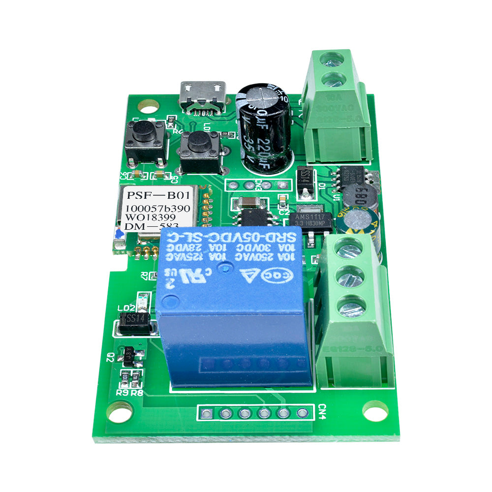
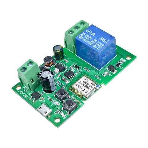 Translation missing: en.products.product.regular_price $8.99{"id":4364187009095,"title":"DDC-432 4 button 3-digit Digital Tube Dual DC5-30V MOS Delay Controller Display","handle":"ddc-432-4-button-3-digit-digital-tube-dual-dc5-30v-mos-delay-controller-display","description":"\u003cdiv\u003e\n\u003cspan\u003e\u003cstrong\u003eDescription:\u003c\/strong\u003e\u003c\/span\u003e\u003cbr\u003e\u003cspan\u003eDual MOS parallel active output, lower internal resistance, larger current, strong power interface, clear and simple, powerful, one-button emergency stop function (STOP button), with reverse connection protection, reverse connection, no burning, power-off memory. Increase Sleep mode, after enabling, no operation within 5 minutes, automatically turn off the display, wake up any button! You can set different OP, CL, LOP parameters, these parameters are independent of each other, save the setting parameters automatically power-down save and other functions, Almost all the needs!\u003c\/span\u003e\n\u003c\/div\u003e\n\u003cdiv\u003e\n\u003cspan\u003e\u003cstrong\u003e1.Product manual\u003c\/strong\u003e\u003c\/span\u003e\u003cbr\u003e\u003cspan\u003eWorking voltage: DC5V-DC30V (wide voltage anti-connection protection)\u003c\/span\u003e\u003cbr\u003e\u003cspan\u003eTrigger signal source: high-level trigger DC 3.0V—24V signal ground and system ground to improve the system's anti-interference ability can also short-circuit the ground\u003c\/span\u003e\u003cbr\u003e\u003cspan\u003eOutput capacity: DC DC 5V--36V, continuous current 15A at normal temperature, power 400W! Under the condition of auxiliary heat dissipation, the maximum current can reach 30A\u003c\/span\u003e\u003cbr\u003e\u003cspan\u003eProduct size: 64mm*35mm*19.3mm\u003c\/span\u003e\u003cbr\u003e\u003cspan\u003eMounting hole: diameter 3mm\u003c\/span\u003e\u003cbr\u003e\u003cspan\u003eWorking temperature: -40 ° C ~ 85 ° C\u003c\/span\u003e\n\u003c\/div\u003e\n\u003cdiv\u003e\n\u003cspan\u003e\u003cstrong\u003e2.Operating mode\u003c\/strong\u003e\u003c\/span\u003e\u003cbr\u003e\u003cspan\u003eP1 mode: After the signal is triggered, the MOS transistor turns on the OP time and then turns off; in the OP time, the following operation\u003c\/span\u003e\u003cbr\u003e\u003cspan\u003eP1.1: The signal is triggered again.\u003c\/span\u003e\u003cbr\u003e\u003cspan\u003eP1.2: Signal triggers re-timed again\u003c\/span\u003e\u003cbr\u003e\u003cspan\u003eP1.3: The signal triggers reset again, the MOS tube is disconnected, and the timing is stopped.\u003c\/span\u003e\u003cbr\u003e\u003cspan\u003eP-2: Give the trigger signal, after the MOS transistor is disconnected from the CL time, the MOS transistor turns on the OP time. After the timing is completed, the MOS transistor is disconnected.\u003c\/span\u003e\u003cbr\u003e\u003cspan\u003eP3.1: Give the trigger signal, after the MOS transistor turns on the OP time, the MOS tube turns off the CL time, then loops the above action, the signal is given again in the loop, the MOS tube is disconnected, the timing is stopped; the number of cycles (LOP) can be set.\u003c\/span\u003e\u003cbr\u003e\u003cspan\u003eP3.2: No need to trigger signal after power-on, MOS tube turns on OP time, MOS tube disconnects CL time, loops the above action; loop number (LOP) can be set\u003c\/span\u003e\u003cbr\u003e\u003cspan\u003eP-4: Signal hold function If there is a trigger signal, the timing is cleared, the MOS transistor remains on; when the signal disappears, the MOS transistor is disconnected after timing the OP; during the timing, there is a signal and the timing is cleared.\u003c\/span\u003e\n\u003c\/div\u003e\n\u003cdiv\u003e\n\u003cspan\u003e\u003cstrong\u003e3.Relay enable mode\u003c\/strong\u003e\u003c\/span\u003e\u003cbr\u003e\u003cspan\u003eON : MOS tube is allowed to conduct during OP conduction time\u003c\/span\u003e\u003cbr\u003e\u003cspan\u003eOFF : MOS tube is disabled, always off\u003c\/span\u003e\u003cbr\u003e\u003cspan\u003eShort press the STOP button on the main interface to switch between ON and OFF. The current state will flash, then return to the main interface. This function is the emergency stop function. One button is used to open and close the MOS tube.\u003c\/span\u003e\n\u003c\/div\u003e\n\u003cdiv\u003e\n\u003cspan\u003e\u003cstrong\u003e4.Sleep mode (long press the stop button to view the current mode)\u003c\/strong\u003e\u003c\/span\u003e\u003cbr\u003e\u003cspan\u003eC-P sleep mode: within five minutes, without any operation, the digital tube automatically turns off the display, the program runs normally.\u003c\/span\u003e\u003cbr\u003e\u003cspan\u003eO-d normal mode: the digital tube is always on display\u003c\/span\u003e\u003cbr\u003e\u003cspan\u003ePress and hold the STOP button for 2 seconds and then release to switch the C-P and O-d states. The current state will flash and then return to the main interface.\u003c\/span\u003e\n\u003c\/div\u003e\n\u003cdiv\u003e\n\u003cspan\u003e\u003cstrong\u003e5.Timing range\u003c\/strong\u003e\u003c\/span\u003e\u003cbr\u003e\u003cspan\u003eHow to choose the timing range\u003c\/span\u003e\u003cbr\u003e\u003cspan\u003e1).After setting the parameter value in the mode selection interface, press the STOP button to select the timing range.\u003c\/span\u003e\u003cbr\u003e\u003cspan\u003eXXX. Decimal point is in one place, timing range: 1 second to 999 seconds\u003c\/span\u003e\u003cbr\u003e\u003cspan\u003eXX.X decimal point in ten, timing range: 0.1 seconds to 99.9 seconds\u003c\/span\u003e\u003cbr\u003e\u003cspan\u003eX.X.X. The decimal point is fully illuminated, the timing range is from 1 minute to 999 minutes.\u003c\/span\u003e\n\u003c\/div\u003e\n\u003cdiv\u003e\n\u003cspan\u003e2).For example, if you want to set the OP to 3.2 seconds, move the decimal point to ten digits, and the digital tube displays 03.2.\u003c\/span\u003e\u003cbr\u003e\u003cspan\u003eParameter description: OP on time, CL off time, LOP cycle number 1-999 times, \"---\" stands for infinite loop.\u003c\/span\u003e\u003cbr\u003e\u003cspan\u003eThese parameters are independent of each other, but each mode shares these parameters. For example, when the on-time OP is set to 5 seconds in P1.1, the user wants to switch to the P1.2 mode, then when entering the P1.2 setting corresponding parameters, the OP also It will be 5 seconds.\u003c\/span\u003e\u003cbr\u003e\u003cspan\u003eDisplaying 000 on the main interface and pressing the SET button will display OPL, LOP and corresponding time XXX\u003c\/span\u003e\u003cbr\u003e\u003cspan\u003eIf only OP in the mode, such as mode P1.1, P1.2, P1.3 time, then short press SET button will only display OP and corresponding time.\u003c\/span\u003e\u003cbr\u003e\u003cspan\u003eIf the mode has OP, CL, LOP such as mode P3.1, P3.2 short press SET button will display OP and corresponding time, CL and corresponding time, LOP and corresponding times.\u003c\/span\u003e\u003cbr\u003e\u003cspan\u003eAfter setting the mode, it is very convenient to easily check the parameters set in the current mode by pressing the SET button on the main interface.\u003c\/span\u003e\n\u003c\/div\u003e\n\u003cdiv\u003e\n\u003cspan\u003e\u003cstrong\u003e6.How to set parameters\u003c\/strong\u003e\u003c\/span\u003e\u003cbr\u003e\u003cspan\u003e1) First determine the working mode of the MOS tube\u003c\/span\u003e\u003cbr\u003e\u003cspan\u003eAccording to the working mode of the MOS tube, in the main interface (when the module is powered on, it will flash the current working mode (default P1.1 mode), then enter the main interface \"press and hold the SET button for 2 seconds and then release\" to enter the mode. Select the interface, press the UP, DOWN button to select the mode to be set P1.1~P-4\u003c\/span\u003e\u003cbr\u003e\u003cspan\u003e2) After selecting the mode to be set (for example, P3.2), press the SET button to set the corresponding parameter. At this time, the parameter to be set will flash OP ON time, CL OFF time, LOP cycle number “---” Represents an infinite loop, adjusts the parameter value through UP and DOWN, supports long press (rapid increase or decrease) and short press (increase or decrease 1 unit); after setting the parameter value, select the decimal point position by short pressing the STOP button. , select the timing range (corresponding time 0.1 seconds ~ 999 minutes); short press the SET button to set the next parameter of the current mode, the process is the same as above.\u003c\/span\u003e\u003cbr\u003e\u003cspan\u003e3) After setting the parameters of the selected mode, press and hold the SET button for 2 seconds to release, the currently set mode will flash, then return to the main interface and set the parameters successfully.\u003c\/span\u003e\u003cbr\u003e\u003cspan\u003e4) Main interface: “000” (no decimal point) is displayed when the MOS tube is not working, and the MOS tube has a decimal point in the working state.\u003c\/span\u003e\u003cbr\u003e\u003cspan\u003e5) Mode selection interface: long press SET button to enter, after setting is completed, long press SET button to exit, return to the main interface\u003c\/span\u003e\n\u003c\/div\u003e\n\u003cdiv\u003e\n\u003cspan\u003e\u003cstrong\u003eNote:\u003c\/strong\u003e\u003c\/span\u003e\u003cbr\u003e\u003cspan\u003e\u003cstrong\u003eThe module is an active live output, and the voltage at the output (load) is equal to the input voltage DC\u003c\/strong\u003e\u003c\/span\u003e\n\u003c\/div\u003e\n\u003cdiv\u003e\u003cspan\u003e\u003cstrong\u003e7.Product illustration:\u003c\/strong\u003e\u003c\/span\u003e\u003c\/div\u003e\n\u003cdiv\u003e\u003cimg src=\"https:\/\/pg-cdn-a2.datacaciques.com\/00\/NDAy\/19\/08\/09\/q596misp0rqvln9v\/afe64143851a91a8.png\"\u003e\u003c\/div\u003e\n\u003cdiv\u003e\n\u003cspan\u003e\u003cstrong\u003e8.Package Included:\u003c\/strong\u003e\u003c\/span\u003e\n\u003cdiv\u003e\u003cspan\u003e1*DDC-432 4 button 3-digit Digital Tube Dual DC5-30V MOS Delay Control Board +Case\u003c\/span\u003e\u003c\/div\u003e\n\u003c\/div\u003e","published_at":"2019-11-20T18:48:21+08:00","created_at":"2019-11-20T19:03:21+08:00","vendor":"diymore","type":"Thermostat","tags":[],"price":799,"price_min":799,"price_max":799,"available":true,"price_varies":false,"compare_at_price":null,"compare_at_price_min":0,"compare_at_price_max":0,"compare_at_price_varies":false,"variants":[{"id":31297845624903,"title":"Default Title","option1":"Default Title","option2":null,"option3":null,"sku":"100038","requires_shipping":true,"taxable":true,"featured_image":null,"available":true,"name":"DDC-432 4 button 3-digit Digital Tube Dual DC5-30V MOS Delay Controller Display","public_title":null,"options":["Default Title"],"price":799,"weight":0,"compare_at_price":null,"inventory_management":null,"barcode":null,"requires_selling_plan":false,"selling_plan_allocations":[],"quantity_rule":{"min":1,"max":null,"increment":1}}],"images":["\/\/www.diymore.cc\/cdn\/shop\/products\/100038_8_537.jpg?v=1588669027","\/\/www.diymore.cc\/cdn\/shop\/products\/100038_1_228.jpg?v=1588669027","\/\/www.diymore.cc\/cdn\/shop\/products\/100038_4_813.jpg?v=1588669027","\/\/www.diymore.cc\/cdn\/shop\/products\/100038_5_479.jpg?v=1588669027","\/\/www.diymore.cc\/cdn\/shop\/products\/100038_7_167.jpg?v=1588669027"],"featured_image":"\/\/www.diymore.cc\/cdn\/shop\/products\/100038_8_537.jpg?v=1588669027","options":["Title"],"media":[{"alt":"Ddc-432 4 Button 3-Digit Digital Tube Dual Dc5-30V Mos Delay Controller Display Thermostat","id":6679915167815,"position":1,"preview_image":{"aspect_ratio":1.0,"height":1000,"width":1000,"src":"\/\/www.diymore.cc\/cdn\/shop\/products\/100038_8_537.jpg?v=1588669027"},"aspect_ratio":1.0,"height":1000,"media_type":"image","src":"\/\/www.diymore.cc\/cdn\/shop\/products\/100038_8_537.jpg?v=1588669027","width":1000},{"alt":"Ddc-432 4 Button 3-Digit Digital Tube Dual Dc5-30V Mos Delay Controller Display Thermostat","id":6679915233351,"position":2,"preview_image":{"aspect_ratio":1.0,"height":1000,"width":1000,"src":"\/\/www.diymore.cc\/cdn\/shop\/products\/100038_1_228.jpg?v=1588669027"},"aspect_ratio":1.0,"height":1000,"media_type":"image","src":"\/\/www.diymore.cc\/cdn\/shop\/products\/100038_1_228.jpg?v=1588669027","width":1000},{"alt":"Ddc-432 4 Button 3-Digit Digital Tube Dual Dc5-30V Mos Delay Controller Display Thermostat","id":6679915397191,"position":3,"preview_image":{"aspect_ratio":1.0,"height":1000,"width":1000,"src":"\/\/www.diymore.cc\/cdn\/shop\/products\/100038_4_813.jpg?v=1588669027"},"aspect_ratio":1.0,"height":1000,"media_type":"image","src":"\/\/www.diymore.cc\/cdn\/shop\/products\/100038_4_813.jpg?v=1588669027","width":1000},{"alt":"Ddc-432 4 Button 3-Digit Digital Tube Dual Dc5-30V Mos Delay Controller Display Thermostat","id":6679915561031,"position":4,"preview_image":{"aspect_ratio":1.0,"height":1000,"width":1000,"src":"\/\/www.diymore.cc\/cdn\/shop\/products\/100038_5_479.jpg?v=1588669027"},"aspect_ratio":1.0,"height":1000,"media_type":"image","src":"\/\/www.diymore.cc\/cdn\/shop\/products\/100038_5_479.jpg?v=1588669027","width":1000},{"alt":"Ddc-432 4 Button 3-Digit Digital Tube Dual Dc5-30V Mos Delay Controller Display Thermostat","id":6679915626567,"position":5,"preview_image":{"aspect_ratio":1.0,"height":1000,"width":1000,"src":"\/\/www.diymore.cc\/cdn\/shop\/products\/100038_7_167.jpg?v=1588669027"},"aspect_ratio":1.0,"height":1000,"media_type":"image","src":"\/\/www.diymore.cc\/cdn\/shop\/products\/100038_7_167.jpg?v=1588669027","width":1000}],"requires_selling_plan":false,"selling_plan_groups":[],"content":"\u003cdiv\u003e\n\u003cspan\u003e\u003cstrong\u003eDescription:\u003c\/strong\u003e\u003c\/span\u003e\u003cbr\u003e\u003cspan\u003eDual MOS parallel active output, lower internal resistance, larger current, strong power interface, clear and simple, powerful, one-button emergency stop function (STOP button), with reverse connection protection, reverse connection, no burning, power-off memory. Increase Sleep mode, after enabling, no operation within 5 minutes, automatically turn off the display, wake up any button! You can set different OP, CL, LOP parameters, these parameters are independent of each other, save the setting parameters automatically power-down save and other functions, Almost all the needs!\u003c\/span\u003e\n\u003c\/div\u003e\n\u003cdiv\u003e\n\u003cspan\u003e\u003cstrong\u003e1.Product manual\u003c\/strong\u003e\u003c\/span\u003e\u003cbr\u003e\u003cspan\u003eWorking voltage: DC5V-DC30V (wide voltage anti-connection protection)\u003c\/span\u003e\u003cbr\u003e\u003cspan\u003eTrigger signal source: high-level trigger DC 3.0V—24V signal ground and system ground to improve the system's anti-interference ability can also short-circuit the ground\u003c\/span\u003e\u003cbr\u003e\u003cspan\u003eOutput capacity: DC DC 5V--36V, continuous current 15A at normal temperature, power 400W! Under the condition of auxiliary heat dissipation, the maximum current can reach 30A\u003c\/span\u003e\u003cbr\u003e\u003cspan\u003eProduct size: 64mm*35mm*19.3mm\u003c\/span\u003e\u003cbr\u003e\u003cspan\u003eMounting hole: diameter 3mm\u003c\/span\u003e\u003cbr\u003e\u003cspan\u003eWorking temperature: -40 ° C ~ 85 ° C\u003c\/span\u003e\n\u003c\/div\u003e\n\u003cdiv\u003e\n\u003cspan\u003e\u003cstrong\u003e2.Operating mode\u003c\/strong\u003e\u003c\/span\u003e\u003cbr\u003e\u003cspan\u003eP1 mode: After the signal is triggered, the MOS transistor turns on the OP time and then turns off; in the OP time, the following operation\u003c\/span\u003e\u003cbr\u003e\u003cspan\u003eP1.1: The signal is triggered again.\u003c\/span\u003e\u003cbr\u003e\u003cspan\u003eP1.2: Signal triggers re-timed again\u003c\/span\u003e\u003cbr\u003e\u003cspan\u003eP1.3: The signal triggers reset again, the MOS tube is disconnected, and the timing is stopped.\u003c\/span\u003e\u003cbr\u003e\u003cspan\u003eP-2: Give the trigger signal, after the MOS transistor is disconnected from the CL time, the MOS transistor turns on the OP time. After the timing is completed, the MOS transistor is disconnected.\u003c\/span\u003e\u003cbr\u003e\u003cspan\u003eP3.1: Give the trigger signal, after the MOS transistor turns on the OP time, the MOS tube turns off the CL time, then loops the above action, the signal is given again in the loop, the MOS tube is disconnected, the timing is stopped; the number of cycles (LOP) can be set.\u003c\/span\u003e\u003cbr\u003e\u003cspan\u003eP3.2: No need to trigger signal after power-on, MOS tube turns on OP time, MOS tube disconnects CL time, loops the above action; loop number (LOP) can be set\u003c\/span\u003e\u003cbr\u003e\u003cspan\u003eP-4: Signal hold function If there is a trigger signal, the timing is cleared, the MOS transistor remains on; when the signal disappears, the MOS transistor is disconnected after timing the OP; during the timing, there is a signal and the timing is cleared.\u003c\/span\u003e\n\u003c\/div\u003e\n\u003cdiv\u003e\n\u003cspan\u003e\u003cstrong\u003e3.Relay enable mode\u003c\/strong\u003e\u003c\/span\u003e\u003cbr\u003e\u003cspan\u003eON : MOS tube is allowed to conduct during OP conduction time\u003c\/span\u003e\u003cbr\u003e\u003cspan\u003eOFF : MOS tube is disabled, always off\u003c\/span\u003e\u003cbr\u003e\u003cspan\u003eShort press the STOP button on the main interface to switch between ON and OFF. The current state will flash, then return to the main interface. This function is the emergency stop function. One button is used to open and close the MOS tube.\u003c\/span\u003e\n\u003c\/div\u003e\n\u003cdiv\u003e\n\u003cspan\u003e\u003cstrong\u003e4.Sleep mode (long press the stop button to view the current mode)\u003c\/strong\u003e\u003c\/span\u003e\u003cbr\u003e\u003cspan\u003eC-P sleep mode: within five minutes, without any operation, the digital tube automatically turns off the display, the program runs normally.\u003c\/span\u003e\u003cbr\u003e\u003cspan\u003eO-d normal mode: the digital tube is always on display\u003c\/span\u003e\u003cbr\u003e\u003cspan\u003ePress and hold the STOP button for 2 seconds and then release to switch the C-P and O-d states. The current state will flash and then return to the main interface.\u003c\/span\u003e\n\u003c\/div\u003e\n\u003cdiv\u003e\n\u003cspan\u003e\u003cstrong\u003e5.Timing range\u003c\/strong\u003e\u003c\/span\u003e\u003cbr\u003e\u003cspan\u003eHow to choose the timing range\u003c\/span\u003e\u003cbr\u003e\u003cspan\u003e1).After setting the parameter value in the mode selection interface, press the STOP button to select the timing range.\u003c\/span\u003e\u003cbr\u003e\u003cspan\u003eXXX. Decimal point is in one place, timing range: 1 second to 999 seconds\u003c\/span\u003e\u003cbr\u003e\u003cspan\u003eXX.X decimal point in ten, timing range: 0.1 seconds to 99.9 seconds\u003c\/span\u003e\u003cbr\u003e\u003cspan\u003eX.X.X. The decimal point is fully illuminated, the timing range is from 1 minute to 999 minutes.\u003c\/span\u003e\n\u003c\/div\u003e\n\u003cdiv\u003e\n\u003cspan\u003e2).For example, if you want to set the OP to 3.2 seconds, move the decimal point to ten digits, and the digital tube displays 03.2.\u003c\/span\u003e\u003cbr\u003e\u003cspan\u003eParameter description: OP on time, CL off time, LOP cycle number 1-999 times, \"---\" stands for infinite loop.\u003c\/span\u003e\u003cbr\u003e\u003cspan\u003eThese parameters are independent of each other, but each mode shares these parameters. For example, when the on-time OP is set to 5 seconds in P1.1, the user wants to switch to the P1.2 mode, then when entering the P1.2 setting corresponding parameters, the OP also It will be 5 seconds.\u003c\/span\u003e\u003cbr\u003e\u003cspan\u003eDisplaying 000 on the main interface and pressing the SET button will display OPL, LOP and corresponding time XXX\u003c\/span\u003e\u003cbr\u003e\u003cspan\u003eIf only OP in the mode, such as mode P1.1, P1.2, P1.3 time, then short press SET button will only display OP and corresponding time.\u003c\/span\u003e\u003cbr\u003e\u003cspan\u003eIf the mode has OP, CL, LOP such as mode P3.1, P3.2 short press SET button will display OP and corresponding time, CL and corresponding time, LOP and corresponding times.\u003c\/span\u003e\u003cbr\u003e\u003cspan\u003eAfter setting the mode, it is very convenient to easily check the parameters set in the current mode by pressing the SET button on the main interface.\u003c\/span\u003e\n\u003c\/div\u003e\n\u003cdiv\u003e\n\u003cspan\u003e\u003cstrong\u003e6.How to set parameters\u003c\/strong\u003e\u003c\/span\u003e\u003cbr\u003e\u003cspan\u003e1) First determine the working mode of the MOS tube\u003c\/span\u003e\u003cbr\u003e\u003cspan\u003eAccording to the working mode of the MOS tube, in the main interface (when the module is powered on, it will flash the current working mode (default P1.1 mode), then enter the main interface \"press and hold the SET button for 2 seconds and then release\" to enter the mode. Select the interface, press the UP, DOWN button to select the mode to be set P1.1~P-4\u003c\/span\u003e\u003cbr\u003e\u003cspan\u003e2) After selecting the mode to be set (for example, P3.2), press the SET button to set the corresponding parameter. At this time, the parameter to be set will flash OP ON time, CL OFF time, LOP cycle number “---” Represents an infinite loop, adjusts the parameter value through UP and DOWN, supports long press (rapid increase or decrease) and short press (increase or decrease 1 unit); after setting the parameter value, select the decimal point position by short pressing the STOP button. , select the timing range (corresponding time 0.1 seconds ~ 999 minutes); short press the SET button to set the next parameter of the current mode, the process is the same as above.\u003c\/span\u003e\u003cbr\u003e\u003cspan\u003e3) After setting the parameters of the selected mode, press and hold the SET button for 2 seconds to release, the currently set mode will flash, then return to the main interface and set the parameters successfully.\u003c\/span\u003e\u003cbr\u003e\u003cspan\u003e4) Main interface: “000” (no decimal point) is displayed when the MOS tube is not working, and the MOS tube has a decimal point in the working state.\u003c\/span\u003e\u003cbr\u003e\u003cspan\u003e5) Mode selection interface: long press SET button to enter, after setting is completed, long press SET button to exit, return to the main interface\u003c\/span\u003e\n\u003c\/div\u003e\n\u003cdiv\u003e\n\u003cspan\u003e\u003cstrong\u003eNote:\u003c\/strong\u003e\u003c\/span\u003e\u003cbr\u003e\u003cspan\u003e\u003cstrong\u003eThe module is an active live output, and the voltage at the output (load) is equal to the input voltage DC\u003c\/strong\u003e\u003c\/span\u003e\n\u003c\/div\u003e\n\u003cdiv\u003e\u003cspan\u003e\u003cstrong\u003e7.Product illustration:\u003c\/strong\u003e\u003c\/span\u003e\u003c\/div\u003e\n\u003cdiv\u003e\u003cimg src=\"https:\/\/pg-cdn-a2.datacaciques.com\/00\/NDAy\/19\/08\/09\/q596misp0rqvln9v\/afe64143851a91a8.png\"\u003e\u003c\/div\u003e\n\u003cdiv\u003e\n\u003cspan\u003e\u003cstrong\u003e8.Package Included:\u003c\/strong\u003e\u003c\/span\u003e\n\u003cdiv\u003e\u003cspan\u003e1*DDC-432 4 button 3-digit Digital Tube Dual DC5-30V MOS Delay Control Board +Case\u003c\/span\u003e\u003c\/div\u003e\n\u003c\/div\u003e"}
 -
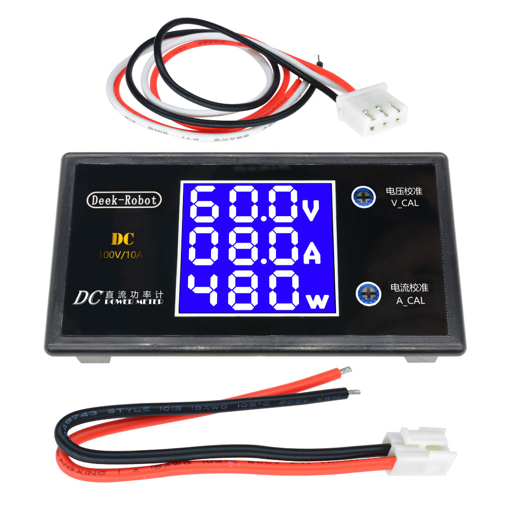
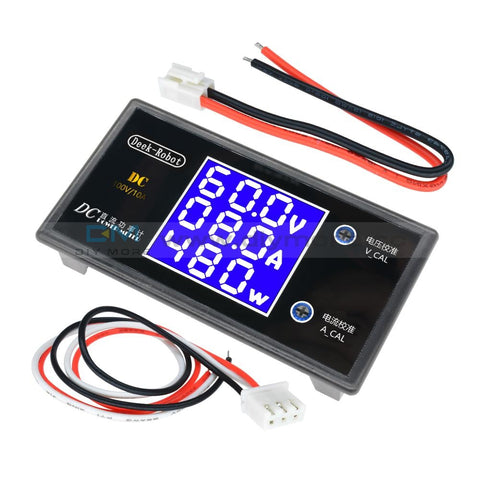 Translation missing: en.products.product.regular_price $7.99{"id":4364187009095,"title":"DDC-432 4 button 3-digit Digital Tube Dual DC5-30V MOS Delay Controller Display","handle":"ddc-432-4-button-3-digit-digital-tube-dual-dc5-30v-mos-delay-controller-display","description":"\u003cdiv\u003e\n\u003cspan\u003e\u003cstrong\u003eDescription:\u003c\/strong\u003e\u003c\/span\u003e\u003cbr\u003e\u003cspan\u003eDual MOS parallel active output, lower internal resistance, larger current, strong power interface, clear and simple, powerful, one-button emergency stop function (STOP button), with reverse connection protection, reverse connection, no burning, power-off memory. Increase Sleep mode, after enabling, no operation within 5 minutes, automatically turn off the display, wake up any button! You can set different OP, CL, LOP parameters, these parameters are independent of each other, save the setting parameters automatically power-down save and other functions, Almost all the needs!\u003c\/span\u003e\n\u003c\/div\u003e\n\u003cdiv\u003e\n\u003cspan\u003e\u003cstrong\u003e1.Product manual\u003c\/strong\u003e\u003c\/span\u003e\u003cbr\u003e\u003cspan\u003eWorking voltage: DC5V-DC30V (wide voltage anti-connection protection)\u003c\/span\u003e\u003cbr\u003e\u003cspan\u003eTrigger signal source: high-level trigger DC 3.0V—24V signal ground and system ground to improve the system's anti-interference ability can also short-circuit the ground\u003c\/span\u003e\u003cbr\u003e\u003cspan\u003eOutput capacity: DC DC 5V--36V, continuous current 15A at normal temperature, power 400W! Under the condition of auxiliary heat dissipation, the maximum current can reach 30A\u003c\/span\u003e\u003cbr\u003e\u003cspan\u003eProduct size: 64mm*35mm*19.3mm\u003c\/span\u003e\u003cbr\u003e\u003cspan\u003eMounting hole: diameter 3mm\u003c\/span\u003e\u003cbr\u003e\u003cspan\u003eWorking temperature: -40 ° C ~ 85 ° C\u003c\/span\u003e\n\u003c\/div\u003e\n\u003cdiv\u003e\n\u003cspan\u003e\u003cstrong\u003e2.Operating mode\u003c\/strong\u003e\u003c\/span\u003e\u003cbr\u003e\u003cspan\u003eP1 mode: After the signal is triggered, the MOS transistor turns on the OP time and then turns off; in the OP time, the following operation\u003c\/span\u003e\u003cbr\u003e\u003cspan\u003eP1.1: The signal is triggered again.\u003c\/span\u003e\u003cbr\u003e\u003cspan\u003eP1.2: Signal triggers re-timed again\u003c\/span\u003e\u003cbr\u003e\u003cspan\u003eP1.3: The signal triggers reset again, the MOS tube is disconnected, and the timing is stopped.\u003c\/span\u003e\u003cbr\u003e\u003cspan\u003eP-2: Give the trigger signal, after the MOS transistor is disconnected from the CL time, the MOS transistor turns on the OP time. After the timing is completed, the MOS transistor is disconnected.\u003c\/span\u003e\u003cbr\u003e\u003cspan\u003eP3.1: Give the trigger signal, after the MOS transistor turns on the OP time, the MOS tube turns off the CL time, then loops the above action, the signal is given again in the loop, the MOS tube is disconnected, the timing is stopped; the number of cycles (LOP) can be set.\u003c\/span\u003e\u003cbr\u003e\u003cspan\u003eP3.2: No need to trigger signal after power-on, MOS tube turns on OP time, MOS tube disconnects CL time, loops the above action; loop number (LOP) can be set\u003c\/span\u003e\u003cbr\u003e\u003cspan\u003eP-4: Signal hold function If there is a trigger signal, the timing is cleared, the MOS transistor remains on; when the signal disappears, the MOS transistor is disconnected after timing the OP; during the timing, there is a signal and the timing is cleared.\u003c\/span\u003e\n\u003c\/div\u003e\n\u003cdiv\u003e\n\u003cspan\u003e\u003cstrong\u003e3.Relay enable mode\u003c\/strong\u003e\u003c\/span\u003e\u003cbr\u003e\u003cspan\u003eON : MOS tube is allowed to conduct during OP conduction time\u003c\/span\u003e\u003cbr\u003e\u003cspan\u003eOFF : MOS tube is disabled, always off\u003c\/span\u003e\u003cbr\u003e\u003cspan\u003eShort press the STOP button on the main interface to switch between ON and OFF. The current state will flash, then return to the main interface. This function is the emergency stop function. One button is used to open and close the MOS tube.\u003c\/span\u003e\n\u003c\/div\u003e\n\u003cdiv\u003e\n\u003cspan\u003e\u003cstrong\u003e4.Sleep mode (long press the stop button to view the current mode)\u003c\/strong\u003e\u003c\/span\u003e\u003cbr\u003e\u003cspan\u003eC-P sleep mode: within five minutes, without any operation, the digital tube automatically turns off the display, the program runs normally.\u003c\/span\u003e\u003cbr\u003e\u003cspan\u003eO-d normal mode: the digital tube is always on display\u003c\/span\u003e\u003cbr\u003e\u003cspan\u003ePress and hold the STOP button for 2 seconds and then release to switch the C-P and O-d states. The current state will flash and then return to the main interface.\u003c\/span\u003e\n\u003c\/div\u003e\n\u003cdiv\u003e\n\u003cspan\u003e\u003cstrong\u003e5.Timing range\u003c\/strong\u003e\u003c\/span\u003e\u003cbr\u003e\u003cspan\u003eHow to choose the timing range\u003c\/span\u003e\u003cbr\u003e\u003cspan\u003e1).After setting the parameter value in the mode selection interface, press the STOP button to select the timing range.\u003c\/span\u003e\u003cbr\u003e\u003cspan\u003eXXX. Decimal point is in one place, timing range: 1 second to 999 seconds\u003c\/span\u003e\u003cbr\u003e\u003cspan\u003eXX.X decimal point in ten, timing range: 0.1 seconds to 99.9 seconds\u003c\/span\u003e\u003cbr\u003e\u003cspan\u003eX.X.X. The decimal point is fully illuminated, the timing range is from 1 minute to 999 minutes.\u003c\/span\u003e\n\u003c\/div\u003e\n\u003cdiv\u003e\n\u003cspan\u003e2).For example, if you want to set the OP to 3.2 seconds, move the decimal point to ten digits, and the digital tube displays 03.2.\u003c\/span\u003e\u003cbr\u003e\u003cspan\u003eParameter description: OP on time, CL off time, LOP cycle number 1-999 times, \"---\" stands for infinite loop.\u003c\/span\u003e\u003cbr\u003e\u003cspan\u003eThese parameters are independent of each other, but each mode shares these parameters. For example, when the on-time OP is set to 5 seconds in P1.1, the user wants to switch to the P1.2 mode, then when entering the P1.2 setting corresponding parameters, the OP also It will be 5 seconds.\u003c\/span\u003e\u003cbr\u003e\u003cspan\u003eDisplaying 000 on the main interface and pressing the SET button will display OPL, LOP and corresponding time XXX\u003c\/span\u003e\u003cbr\u003e\u003cspan\u003eIf only OP in the mode, such as mode P1.1, P1.2, P1.3 time, then short press SET button will only display OP and corresponding time.\u003c\/span\u003e\u003cbr\u003e\u003cspan\u003eIf the mode has OP, CL, LOP such as mode P3.1, P3.2 short press SET button will display OP and corresponding time, CL and corresponding time, LOP and corresponding times.\u003c\/span\u003e\u003cbr\u003e\u003cspan\u003eAfter setting the mode, it is very convenient to easily check the parameters set in the current mode by pressing the SET button on the main interface.\u003c\/span\u003e\n\u003c\/div\u003e\n\u003cdiv\u003e\n\u003cspan\u003e\u003cstrong\u003e6.How to set parameters\u003c\/strong\u003e\u003c\/span\u003e\u003cbr\u003e\u003cspan\u003e1) First determine the working mode of the MOS tube\u003c\/span\u003e\u003cbr\u003e\u003cspan\u003eAccording to the working mode of the MOS tube, in the main interface (when the module is powered on, it will flash the current working mode (default P1.1 mode), then enter the main interface \"press and hold the SET button for 2 seconds and then release\" to enter the mode. Select the interface, press the UP, DOWN button to select the mode to be set P1.1~P-4\u003c\/span\u003e\u003cbr\u003e\u003cspan\u003e2) After selecting the mode to be set (for example, P3.2), press the SET button to set the corresponding parameter. At this time, the parameter to be set will flash OP ON time, CL OFF time, LOP cycle number “---” Represents an infinite loop, adjusts the parameter value through UP and DOWN, supports long press (rapid increase or decrease) and short press (increase or decrease 1 unit); after setting the parameter value, select the decimal point position by short pressing the STOP button. , select the timing range (corresponding time 0.1 seconds ~ 999 minutes); short press the SET button to set the next parameter of the current mode, the process is the same as above.\u003c\/span\u003e\u003cbr\u003e\u003cspan\u003e3) After setting the parameters of the selected mode, press and hold the SET button for 2 seconds to release, the currently set mode will flash, then return to the main interface and set the parameters successfully.\u003c\/span\u003e\u003cbr\u003e\u003cspan\u003e4) Main interface: “000” (no decimal point) is displayed when the MOS tube is not working, and the MOS tube has a decimal point in the working state.\u003c\/span\u003e\u003cbr\u003e\u003cspan\u003e5) Mode selection interface: long press SET button to enter, after setting is completed, long press SET button to exit, return to the main interface\u003c\/span\u003e\n\u003c\/div\u003e\n\u003cdiv\u003e\n\u003cspan\u003e\u003cstrong\u003eNote:\u003c\/strong\u003e\u003c\/span\u003e\u003cbr\u003e\u003cspan\u003e\u003cstrong\u003eThe module is an active live output, and the voltage at the output (load) is equal to the input voltage DC\u003c\/strong\u003e\u003c\/span\u003e\n\u003c\/div\u003e\n\u003cdiv\u003e\u003cspan\u003e\u003cstrong\u003e7.Product illustration:\u003c\/strong\u003e\u003c\/span\u003e\u003c\/div\u003e\n\u003cdiv\u003e\u003cimg src=\"https:\/\/pg-cdn-a2.datacaciques.com\/00\/NDAy\/19\/08\/09\/q596misp0rqvln9v\/afe64143851a91a8.png\"\u003e\u003c\/div\u003e\n\u003cdiv\u003e\n\u003cspan\u003e\u003cstrong\u003e8.Package Included:\u003c\/strong\u003e\u003c\/span\u003e\n\u003cdiv\u003e\u003cspan\u003e1*DDC-432 4 button 3-digit Digital Tube Dual DC5-30V MOS Delay Control Board +Case\u003c\/span\u003e\u003c\/div\u003e\n\u003c\/div\u003e","published_at":"2019-11-20T18:48:21+08:00","created_at":"2019-11-20T19:03:21+08:00","vendor":"diymore","type":"Thermostat","tags":[],"price":799,"price_min":799,"price_max":799,"available":true,"price_varies":false,"compare_at_price":null,"compare_at_price_min":0,"compare_at_price_max":0,"compare_at_price_varies":false,"variants":[{"id":31297845624903,"title":"Default Title","option1":"Default Title","option2":null,"option3":null,"sku":"100038","requires_shipping":true,"taxable":true,"featured_image":null,"available":true,"name":"DDC-432 4 button 3-digit Digital Tube Dual DC5-30V MOS Delay Controller Display","public_title":null,"options":["Default Title"],"price":799,"weight":0,"compare_at_price":null,"inventory_management":null,"barcode":null,"requires_selling_plan":false,"selling_plan_allocations":[],"quantity_rule":{"min":1,"max":null,"increment":1}}],"images":["\/\/www.diymore.cc\/cdn\/shop\/products\/100038_8_537.jpg?v=1588669027","\/\/www.diymore.cc\/cdn\/shop\/products\/100038_1_228.jpg?v=1588669027","\/\/www.diymore.cc\/cdn\/shop\/products\/100038_4_813.jpg?v=1588669027","\/\/www.diymore.cc\/cdn\/shop\/products\/100038_5_479.jpg?v=1588669027","\/\/www.diymore.cc\/cdn\/shop\/products\/100038_7_167.jpg?v=1588669027"],"featured_image":"\/\/www.diymore.cc\/cdn\/shop\/products\/100038_8_537.jpg?v=1588669027","options":["Title"],"media":[{"alt":"Ddc-432 4 Button 3-Digit Digital Tube Dual Dc5-30V Mos Delay Controller Display Thermostat","id":6679915167815,"position":1,"preview_image":{"aspect_ratio":1.0,"height":1000,"width":1000,"src":"\/\/www.diymore.cc\/cdn\/shop\/products\/100038_8_537.jpg?v=1588669027"},"aspect_ratio":1.0,"height":1000,"media_type":"image","src":"\/\/www.diymore.cc\/cdn\/shop\/products\/100038_8_537.jpg?v=1588669027","width":1000},{"alt":"Ddc-432 4 Button 3-Digit Digital Tube Dual Dc5-30V Mos Delay Controller Display Thermostat","id":6679915233351,"position":2,"preview_image":{"aspect_ratio":1.0,"height":1000,"width":1000,"src":"\/\/www.diymore.cc\/cdn\/shop\/products\/100038_1_228.jpg?v=1588669027"},"aspect_ratio":1.0,"height":1000,"media_type":"image","src":"\/\/www.diymore.cc\/cdn\/shop\/products\/100038_1_228.jpg?v=1588669027","width":1000},{"alt":"Ddc-432 4 Button 3-Digit Digital Tube Dual Dc5-30V Mos Delay Controller Display Thermostat","id":6679915397191,"position":3,"preview_image":{"aspect_ratio":1.0,"height":1000,"width":1000,"src":"\/\/www.diymore.cc\/cdn\/shop\/products\/100038_4_813.jpg?v=1588669027"},"aspect_ratio":1.0,"height":1000,"media_type":"image","src":"\/\/www.diymore.cc\/cdn\/shop\/products\/100038_4_813.jpg?v=1588669027","width":1000},{"alt":"Ddc-432 4 Button 3-Digit Digital Tube Dual Dc5-30V Mos Delay Controller Display Thermostat","id":6679915561031,"position":4,"preview_image":{"aspect_ratio":1.0,"height":1000,"width":1000,"src":"\/\/www.diymore.cc\/cdn\/shop\/products\/100038_5_479.jpg?v=1588669027"},"aspect_ratio":1.0,"height":1000,"media_type":"image","src":"\/\/www.diymore.cc\/cdn\/shop\/products\/100038_5_479.jpg?v=1588669027","width":1000},{"alt":"Ddc-432 4 Button 3-Digit Digital Tube Dual Dc5-30V Mos Delay Controller Display Thermostat","id":6679915626567,"position":5,"preview_image":{"aspect_ratio":1.0,"height":1000,"width":1000,"src":"\/\/www.diymore.cc\/cdn\/shop\/products\/100038_7_167.jpg?v=1588669027"},"aspect_ratio":1.0,"height":1000,"media_type":"image","src":"\/\/www.diymore.cc\/cdn\/shop\/products\/100038_7_167.jpg?v=1588669027","width":1000}],"requires_selling_plan":false,"selling_plan_groups":[],"content":"\u003cdiv\u003e\n\u003cspan\u003e\u003cstrong\u003eDescription:\u003c\/strong\u003e\u003c\/span\u003e\u003cbr\u003e\u003cspan\u003eDual MOS parallel active output, lower internal resistance, larger current, strong power interface, clear and simple, powerful, one-button emergency stop function (STOP button), with reverse connection protection, reverse connection, no burning, power-off memory. Increase Sleep mode, after enabling, no operation within 5 minutes, automatically turn off the display, wake up any button! You can set different OP, CL, LOP parameters, these parameters are independent of each other, save the setting parameters automatically power-down save and other functions, Almost all the needs!\u003c\/span\u003e\n\u003c\/div\u003e\n\u003cdiv\u003e\n\u003cspan\u003e\u003cstrong\u003e1.Product manual\u003c\/strong\u003e\u003c\/span\u003e\u003cbr\u003e\u003cspan\u003eWorking voltage: DC5V-DC30V (wide voltage anti-connection protection)\u003c\/span\u003e\u003cbr\u003e\u003cspan\u003eTrigger signal source: high-level trigger DC 3.0V—24V signal ground and system ground to improve the system's anti-interference ability can also short-circuit the ground\u003c\/span\u003e\u003cbr\u003e\u003cspan\u003eOutput capacity: DC DC 5V--36V, continuous current 15A at normal temperature, power 400W! Under the condition of auxiliary heat dissipation, the maximum current can reach 30A\u003c\/span\u003e\u003cbr\u003e\u003cspan\u003eProduct size: 64mm*35mm*19.3mm\u003c\/span\u003e\u003cbr\u003e\u003cspan\u003eMounting hole: diameter 3mm\u003c\/span\u003e\u003cbr\u003e\u003cspan\u003eWorking temperature: -40 ° C ~ 85 ° C\u003c\/span\u003e\n\u003c\/div\u003e\n\u003cdiv\u003e\n\u003cspan\u003e\u003cstrong\u003e2.Operating mode\u003c\/strong\u003e\u003c\/span\u003e\u003cbr\u003e\u003cspan\u003eP1 mode: After the signal is triggered, the MOS transistor turns on the OP time and then turns off; in the OP time, the following operation\u003c\/span\u003e\u003cbr\u003e\u003cspan\u003eP1.1: The signal is triggered again.\u003c\/span\u003e\u003cbr\u003e\u003cspan\u003eP1.2: Signal triggers re-timed again\u003c\/span\u003e\u003cbr\u003e\u003cspan\u003eP1.3: The signal triggers reset again, the MOS tube is disconnected, and the timing is stopped.\u003c\/span\u003e\u003cbr\u003e\u003cspan\u003eP-2: Give the trigger signal, after the MOS transistor is disconnected from the CL time, the MOS transistor turns on the OP time. After the timing is completed, the MOS transistor is disconnected.\u003c\/span\u003e\u003cbr\u003e\u003cspan\u003eP3.1: Give the trigger signal, after the MOS transistor turns on the OP time, the MOS tube turns off the CL time, then loops the above action, the signal is given again in the loop, the MOS tube is disconnected, the timing is stopped; the number of cycles (LOP) can be set.\u003c\/span\u003e\u003cbr\u003e\u003cspan\u003eP3.2: No need to trigger signal after power-on, MOS tube turns on OP time, MOS tube disconnects CL time, loops the above action; loop number (LOP) can be set\u003c\/span\u003e\u003cbr\u003e\u003cspan\u003eP-4: Signal hold function If there is a trigger signal, the timing is cleared, the MOS transistor remains on; when the signal disappears, the MOS transistor is disconnected after timing the OP; during the timing, there is a signal and the timing is cleared.\u003c\/span\u003e\n\u003c\/div\u003e\n\u003cdiv\u003e\n\u003cspan\u003e\u003cstrong\u003e3.Relay enable mode\u003c\/strong\u003e\u003c\/span\u003e\u003cbr\u003e\u003cspan\u003eON : MOS tube is allowed to conduct during OP conduction time\u003c\/span\u003e\u003cbr\u003e\u003cspan\u003eOFF : MOS tube is disabled, always off\u003c\/span\u003e\u003cbr\u003e\u003cspan\u003eShort press the STOP button on the main interface to switch between ON and OFF. The current state will flash, then return to the main interface. This function is the emergency stop function. One button is used to open and close the MOS tube.\u003c\/span\u003e\n\u003c\/div\u003e\n\u003cdiv\u003e\n\u003cspan\u003e\u003cstrong\u003e4.Sleep mode (long press the stop button to view the current mode)\u003c\/strong\u003e\u003c\/span\u003e\u003cbr\u003e\u003cspan\u003eC-P sleep mode: within five minutes, without any operation, the digital tube automatically turns off the display, the program runs normally.\u003c\/span\u003e\u003cbr\u003e\u003cspan\u003eO-d normal mode: the digital tube is always on display\u003c\/span\u003e\u003cbr\u003e\u003cspan\u003ePress and hold the STOP button for 2 seconds and then release to switch the C-P and O-d states. The current state will flash and then return to the main interface.\u003c\/span\u003e\n\u003c\/div\u003e\n\u003cdiv\u003e\n\u003cspan\u003e\u003cstrong\u003e5.Timing range\u003c\/strong\u003e\u003c\/span\u003e\u003cbr\u003e\u003cspan\u003eHow to choose the timing range\u003c\/span\u003e\u003cbr\u003e\u003cspan\u003e1).After setting the parameter value in the mode selection interface, press the STOP button to select the timing range.\u003c\/span\u003e\u003cbr\u003e\u003cspan\u003eXXX. Decimal point is in one place, timing range: 1 second to 999 seconds\u003c\/span\u003e\u003cbr\u003e\u003cspan\u003eXX.X decimal point in ten, timing range: 0.1 seconds to 99.9 seconds\u003c\/span\u003e\u003cbr\u003e\u003cspan\u003eX.X.X. The decimal point is fully illuminated, the timing range is from 1 minute to 999 minutes.\u003c\/span\u003e\n\u003c\/div\u003e\n\u003cdiv\u003e\n\u003cspan\u003e2).For example, if you want to set the OP to 3.2 seconds, move the decimal point to ten digits, and the digital tube displays 03.2.\u003c\/span\u003e\u003cbr\u003e\u003cspan\u003eParameter description: OP on time, CL off time, LOP cycle number 1-999 times, \"---\" stands for infinite loop.\u003c\/span\u003e\u003cbr\u003e\u003cspan\u003eThese parameters are independent of each other, but each mode shares these parameters. For example, when the on-time OP is set to 5 seconds in P1.1, the user wants to switch to the P1.2 mode, then when entering the P1.2 setting corresponding parameters, the OP also It will be 5 seconds.\u003c\/span\u003e\u003cbr\u003e\u003cspan\u003eDisplaying 000 on the main interface and pressing the SET button will display OPL, LOP and corresponding time XXX\u003c\/span\u003e\u003cbr\u003e\u003cspan\u003eIf only OP in the mode, such as mode P1.1, P1.2, P1.3 time, then short press SET button will only display OP and corresponding time.\u003c\/span\u003e\u003cbr\u003e\u003cspan\u003eIf the mode has OP, CL, LOP such as mode P3.1, P3.2 short press SET button will display OP and corresponding time, CL and corresponding time, LOP and corresponding times.\u003c\/span\u003e\u003cbr\u003e\u003cspan\u003eAfter setting the mode, it is very convenient to easily check the parameters set in the current mode by pressing the SET button on the main interface.\u003c\/span\u003e\n\u003c\/div\u003e\n\u003cdiv\u003e\n\u003cspan\u003e\u003cstrong\u003e6.How to set parameters\u003c\/strong\u003e\u003c\/span\u003e\u003cbr\u003e\u003cspan\u003e1) First determine the working mode of the MOS tube\u003c\/span\u003e\u003cbr\u003e\u003cspan\u003eAccording to the working mode of the MOS tube, in the main interface (when the module is powered on, it will flash the current working mode (default P1.1 mode), then enter the main interface \"press and hold the SET button for 2 seconds and then release\" to enter the mode. Select the interface, press the UP, DOWN button to select the mode to be set P1.1~P-4\u003c\/span\u003e\u003cbr\u003e\u003cspan\u003e2) After selecting the mode to be set (for example, P3.2), press the SET button to set the corresponding parameter. At this time, the parameter to be set will flash OP ON time, CL OFF time, LOP cycle number “---” Represents an infinite loop, adjusts the parameter value through UP and DOWN, supports long press (rapid increase or decrease) and short press (increase or decrease 1 unit); after setting the parameter value, select the decimal point position by short pressing the STOP button. , select the timing range (corresponding time 0.1 seconds ~ 999 minutes); short press the SET button to set the next parameter of the current mode, the process is the same as above.\u003c\/span\u003e\u003cbr\u003e\u003cspan\u003e3) After setting the parameters of the selected mode, press and hold the SET button for 2 seconds to release, the currently set mode will flash, then return to the main interface and set the parameters successfully.\u003c\/span\u003e\u003cbr\u003e\u003cspan\u003e4) Main interface: “000” (no decimal point) is displayed when the MOS tube is not working, and the MOS tube has a decimal point in the working state.\u003c\/span\u003e\u003cbr\u003e\u003cspan\u003e5) Mode selection interface: long press SET button to enter, after setting is completed, long press SET button to exit, return to the main interface\u003c\/span\u003e\n\u003c\/div\u003e\n\u003cdiv\u003e\n\u003cspan\u003e\u003cstrong\u003eNote:\u003c\/strong\u003e\u003c\/span\u003e\u003cbr\u003e\u003cspan\u003e\u003cstrong\u003eThe module is an active live output, and the voltage at the output (load) is equal to the input voltage DC\u003c\/strong\u003e\u003c\/span\u003e\n\u003c\/div\u003e\n\u003cdiv\u003e\u003cspan\u003e\u003cstrong\u003e7.Product illustration:\u003c\/strong\u003e\u003c\/span\u003e\u003c\/div\u003e\n\u003cdiv\u003e\u003cimg src=\"https:\/\/pg-cdn-a2.datacaciques.com\/00\/NDAy\/19\/08\/09\/q596misp0rqvln9v\/afe64143851a91a8.png\"\u003e\u003c\/div\u003e\n\u003cdiv\u003e\n\u003cspan\u003e\u003cstrong\u003e8.Package Included:\u003c\/strong\u003e\u003c\/span\u003e\n\u003cdiv\u003e\u003cspan\u003e1*DDC-432 4 button 3-digit Digital Tube Dual DC5-30V MOS Delay Control Board +Case\u003c\/span\u003e\u003c\/div\u003e\n\u003c\/div\u003e"}