
Arduino 2A H-Bridge Dual Channel DC Motor Driver Shield Module L298NH Than L298P

Arduino 2A H-Bridge Dual Channel DC Motor Driver Shield Module L298NH Than L298P
SKU:180030
Regular price
$8.99
![]()
- guaranteeQuality checked
- Special gift cardsSpecial gift cards
- Free return Within 60 days
- Consultancy86-0755-85201155

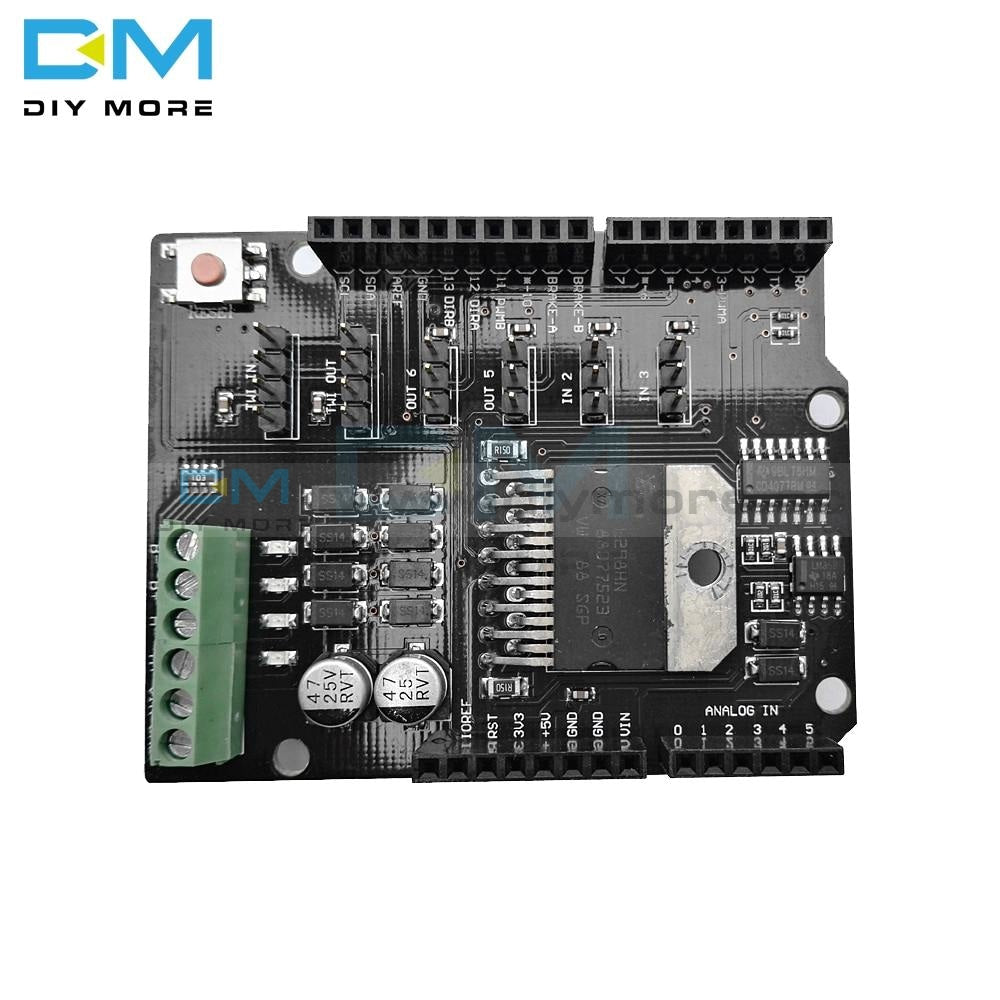
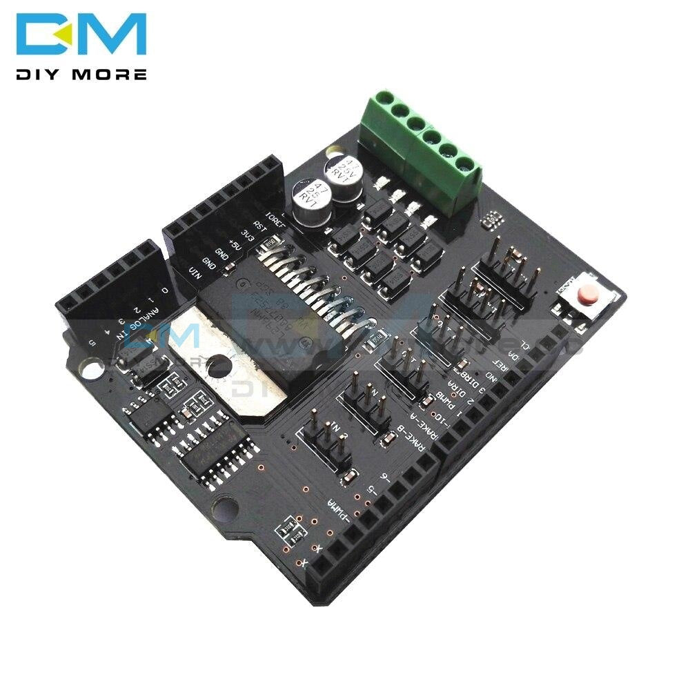
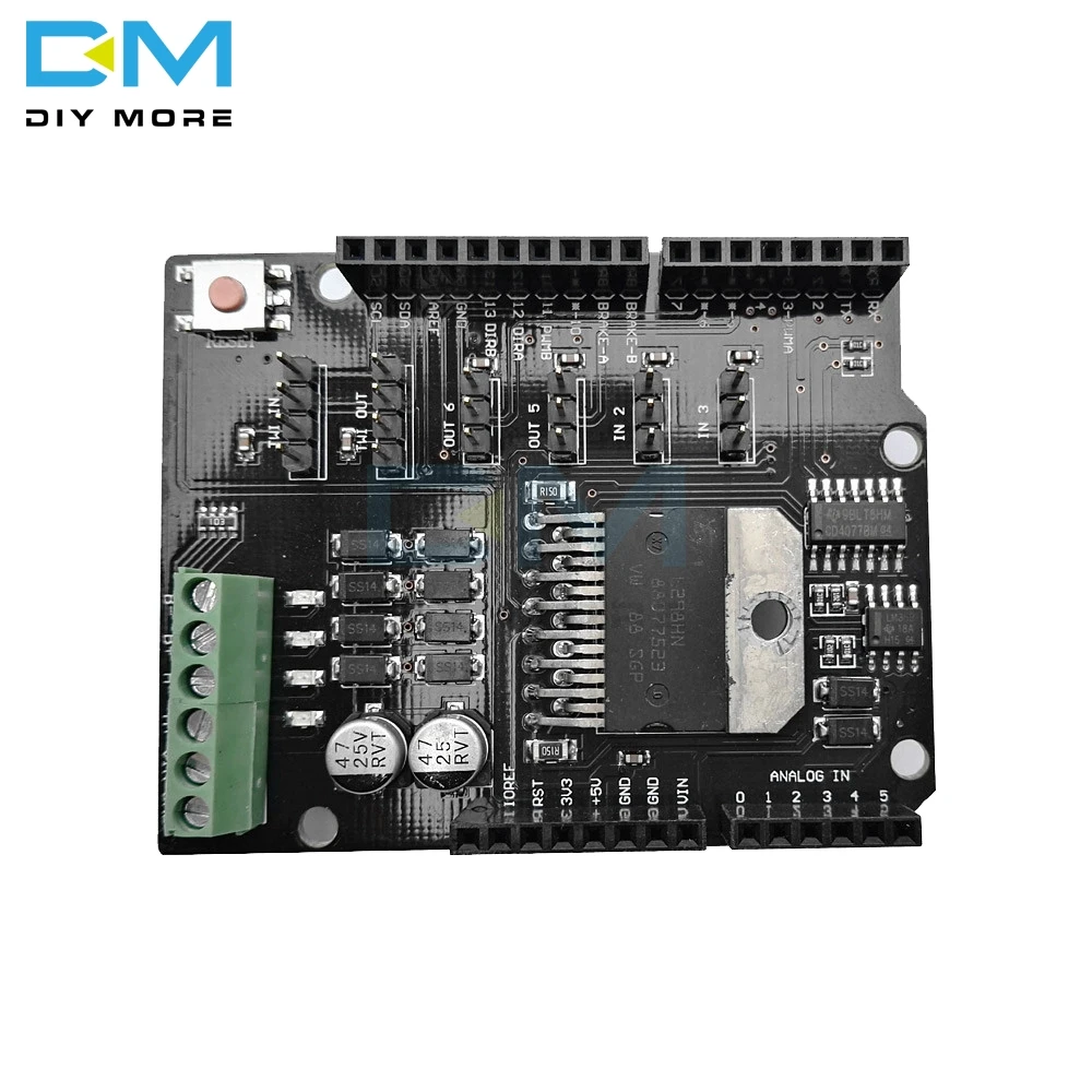
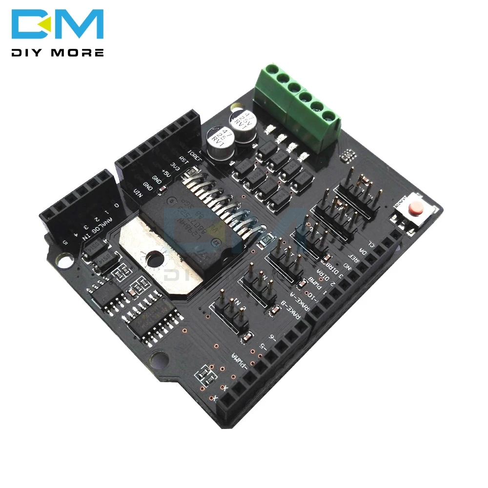
The Motor Shield is based on the L298NH, which is a dual full-bridge driver designed to drive inductive loads such as relays, solenoids, DC and stepping motors. It lets you drive two DC motors with your for arduino board, controlling the speed and direction of each one independently. You can also measure the motor current absorption of each motor, among other features.
•You can find in the Getting Started section all the information you need to configure your board, use the for arduino Software (IDE), and start tinker with coding and electronics.
Technical specs
Operating Voltage 5V to 12V
Motor controller L298HN, Drives 2 DC motors or 1 stepper motor
Max current 2A per channel or 4A max (with external power supply)
Current sensing 1.65V/A
Free running stop and brake function
Power
The Motor Shield must be powered only by an external power supply. Because the L298HN IC mounted on the shield has two separate power connections, one for the logic and one for the motor supply driver. The required motor current often exceeds the maximum USB current rating.
External (non-USB) power can come either from an AC-to-DC adapter (wall-wart) or battery. The adapter can be connected by plugging a 2.1mm center-positive plug into the for arduino 's board power jack on which the motor shield is mounted or by connecting the wires that lead the power supply to the Vin and GND screw terminals, taking care to respect the polarities.
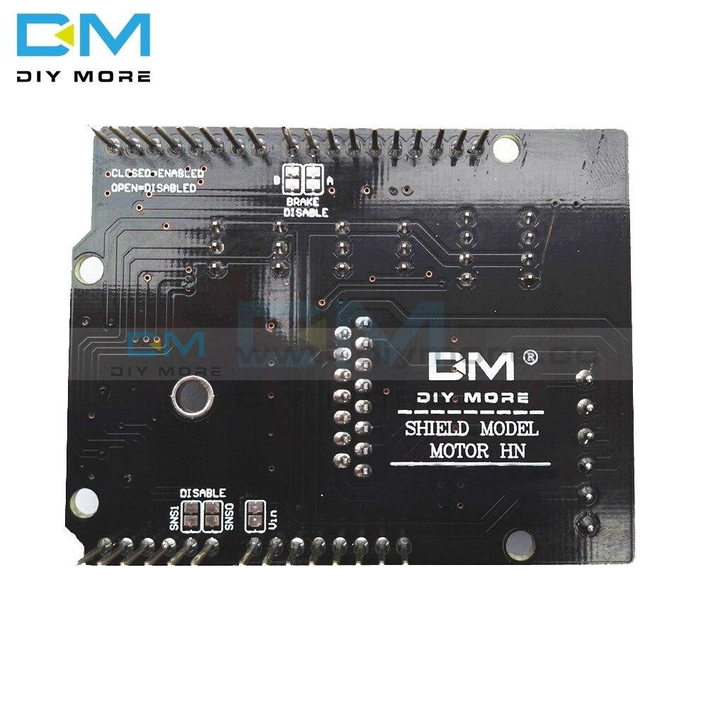
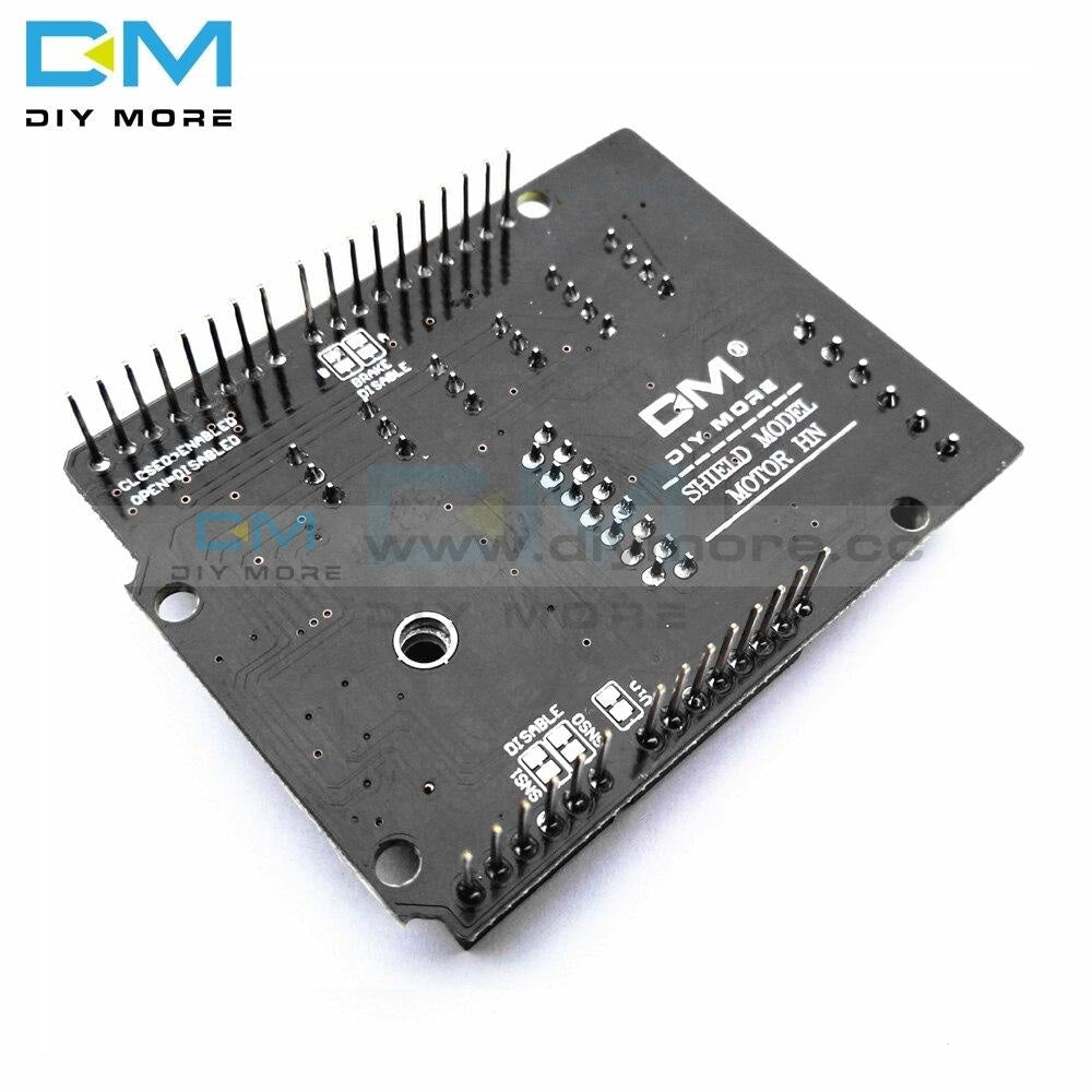
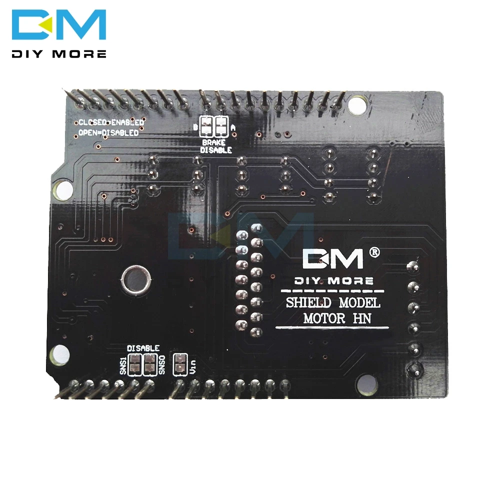
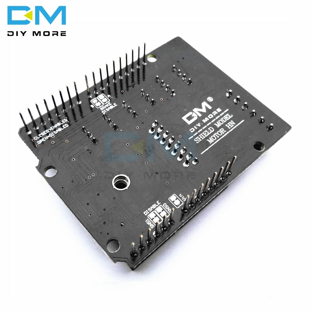
To avoid possible damage to the for arduino board on which the shield is mounted, we reccomend using an external power supply that provides a voltage between 7 and 12V. If your motor require more than 9V we recommend that you separate the power lines of the shield and the for arduino board on which the shield is mounted. This is possible by cutting the "Vin Connect" jumper placed on the back side of the shield. The absolute limit for the Vin at the screw terminals is 18V.
The shield can supply 2 amperes per channel, for a total of 4 amperes maximum.
Input and Output
This shield has two separate channels, called A and B, that each use 4 of the for arduino pins to drive or sense the motor. In total there are 8 pins in use on this shield. You can use each channel separately to drive two DC motors or combine them to drive one bipolar stepper motor. The shield's pins, divided by channel are shown in the table below:
Function pins per Ch. A pins per Ch. B
Direction D12 D13
PWM D3 D11
Brake D9 D8
Current Sensing A0 A1
If you don't need the Brake and the Current Sensing and you also need more pins for your application you can disable this features by cutting the respective jumpers on the back side of the shield.
Motors Connection
Brushed DC motor. You can drive two Brushed DC motors by connecting the two wires of each one in the (+) and (-) screw terminals for each channel A and B. In this way you can control its direction by setting HIGH or LOW the DIR A and DIR B pins, you can control the speed by varying the PWM A and PWM B duty cycle values. The Brake A and Brake B pins, if set HIGH, will effectively brake the DC motors rather than let them slow down by cutting the power. You can measure the current going through the DC motor by reading the SNS0 and SNS1 pins. On each channel will be a voltage proportional to the measured current, which can be read as a normal analog input, through the function analogRead() on the analog input A0 and A1. For your convenience it is calibrated to be 3.3V when the channel is delivering its maximum possible current, that is 2A.
Package Included:
1 x L298NH Dual Channel DC Motor Driver Shield Board


Purchasing & Delivery
Before you make your purchase, it’s helpful to know the measurements of the area you plan to place the furniture. You should also measure any doorways and hallways through which the furniture will pass to get to its final destination.Picking up at the store
Shopify Shop requires that all products are properly inspected BEFORE you take it home to insure there are no surprises. Our team is happy to open all packages and will assist in the inspection process. We will then reseal packages for safe transport. We encourage all customers to bring furniture pads or blankets to protect the items during transport as well as rope or tie downs. Shopify Shop will not be responsible for damage that occurs after leaving the store or during transit. It is the purchaser’s responsibility to make sure the correct items are picked up and in good condition.Delivery
Customers are able to pick the next available delivery day that best fits their schedule. However, to route stops as efficiently as possible, Shopify Shop will provide the time frame. Customers will not be able to choose a time. You will be notified in advance of your scheduled time frame. Please make sure that a responsible adult (18 years or older) will be home at that time.In preparation for your delivery, please remove existing furniture, pictures, mirrors, accessories, etc. to prevent damages. Also insure that the area where you would like your furniture placed is clear of any old furniture and any other items that may obstruct the passageway of the delivery team. Shopify Shop will deliver, assemble, and set-up your new furniture purchase and remove all packing materials from your home. Our delivery crews are not permitted to move your existing furniture or other household items. Delivery personnel will attempt to deliver the purchased items in a safe and controlled manner but will not attempt to place furniture if they feel it will result in damage to the product or your home. Delivery personnel are unable to remove doors, hoist furniture or carry furniture up more than 3 flights of stairs. An elevator must be available for deliveries to the 4th floor and above.
Customer Reviews
No reviews yet
Write a review
Other Customers also buy:
-
 Translation missing: en.products.product.regular_price $23.99{"id":4419938418759,"title":"Arduino 2A H-Bridge Dual Channel DC Motor Driver Shield Module L298NH Than L298P","handle":"replace-l298p-for-arduino-uno-r3-dual-channel-dc-motor-driver-shield-expansion-board-l298nh-module-driving-module-mega2560-one","description":"\u003cdiv\u003e\n\u003cwidget data-widget-type=\"customText\" id=\"33684419\" title=\"Head\" type=\"custom\"\u003e\u003c\/widget\u003e \r \u003cp\u003e\u003cspan style=\"font-size: 16.0px;font-family: trebuchet ms;\"\u003e \u003c\/span\u003e\u003c\/p\u003e \r \u003cdiv\u003e \r \u003cspan style=\"font-size: 16.0px;font-family: trebuchet ms;\"\u003e \u003c\/span\u003e \r \u003cp\u003e\u003cimg src=\"https:\/\/ae01.alicdn.com\/kf\/HTB12JMgilsmBKNjSZFsq6yXSVXaS.jpg\"\u003e\u003c\/p\u003e \r \u003c\/div\u003e \r \u003cdiv\u003e \r \u003cp\u003e\u003cbr\u003e\u003c\/p\u003e \r \u003c\/div\u003e \r \u003cdiv\u003e \r \u003cspan style=\"font-size: 16.0px;font-family: trebuchet ms;\"\u003e \u003c\/span\u003e \r \u003c\/div\u003e \r \u003cdiv\u003e \r \u003cspan style=\"font-size: 16.0px;font-family: trebuchet ms;\"\u003e\u003cspan style=\"font-size: 16.0px;font-family: trebuchet ms;\"\u003eThe Motor Shield is based on the L298NH, which is a dual full-bridge driver designed to drive inductive loads such as relays, solenoids, DC and stepping motors. It lets you drive two DC motors with your for arduino board, controlling the speed and direction of each one independently. You can also measure the motor current absorption of each motor, among other features. \u003c\/span\u003e\u003c\/span\u003e \r \u003c\/div\u003e \r \u003cdiv\u003e \r \u003cspan style=\"font-size: 16.0px;font-family: trebuchet ms;\"\u003e\u003cspan style=\"font-size: 16.0px;font-family: trebuchet ms;\"\u003e•You can find in the Getting Started section all the information you need to configure your board, use the for arduino Software (IDE), and start tinker with coding and electronics. \u003c\/span\u003e\u003c\/span\u003e \r \u003c\/div\u003e \r \u003cdiv\u003e \r \u003cspan style=\"font-size: 16.0px;font-family: trebuchet ms;\"\u003e \u003c\/span\u003e \r \u003c\/div\u003e \r \u003cdiv\u003e \r \u003cspan style=\"font-size: 16.0px;font-family: trebuchet ms;color: #ff6600;\"\u003e\u003cspan style=\"font-size: 16.0px;font-family: trebuchet ms;color: #ff6600;\"\u003e\u003cstrong\u003eTechnical specs\u003c\/strong\u003e\u003c\/span\u003e\u003c\/span\u003e \r \u003c\/div\u003e \r \u003cdiv\u003e \r \u003cspan style=\"font-size: 16.0px;\"\u003e\u003cspan style=\"font-family: trebuchet ms , helvetica , sans-serif;\"\u003e\u003cspan style=\"font-size: 16.0px;font-family: trebuchet ms;\"\u003eOperating Voltage\u003c\/span\u003e\u003cspan style=\"font-size: 16.0px;font-family: trebuchet ms;\"\u003e \u003c\/span\u003e\u003cspan style=\"font-size: 16.0px;font-family: trebuchet ms;\"\u003e5V to 12V\u003c\/span\u003e\u003c\/span\u003e\u003c\/span\u003e \r \u003c\/div\u003e \r \u003cdiv\u003e \r \u003cspan style=\"font-size: 16.0px;\"\u003e\u003cspan style=\"font-family: trebuchet ms , helvetica , sans-serif;\"\u003e\u003cspan style=\"font-size: 16.0px;font-family: trebuchet ms;\"\u003eMotor controller \u003c\/span\u003e\u003cspan style=\"font-size: 16.0px;font-family: trebuchet ms;\"\u003e \u003c\/span\u003e\u003cspan style=\"font-size: 16.0px;font-family: trebuchet ms;\"\u003eL298HN, Drives 2 DC motors or 1 stepper motor\u003c\/span\u003e\u003c\/span\u003e\u003c\/span\u003e \r \u003c\/div\u003e \r \u003cdiv\u003e \r \u003cspan style=\"font-size: 16.0px;\"\u003e\u003cspan style=\"font-family: trebuchet ms , helvetica , sans-serif;\"\u003e\u003cspan style=\"font-size: 16.0px;font-family: trebuchet ms;\"\u003eMax current\u003c\/span\u003e\u003cspan style=\"font-size: 16.0px;font-family: trebuchet ms;\"\u003e \u003c\/span\u003e\u003cspan style=\"font-size: 16.0px;font-family: trebuchet ms;\"\u003e2A per channel or 4A max (with external power supply)\u003c\/span\u003e\u003c\/span\u003e\u003c\/span\u003e \r \u003c\/div\u003e \r \u003cdiv\u003e \r \u003cspan style=\"font-size: 16.0px;\"\u003e\u003cspan style=\"font-family: trebuchet ms , helvetica , sans-serif;\"\u003e\u003cspan style=\"font-size: 16.0px;font-family: trebuchet ms;\"\u003eCurrent sensing\u003c\/span\u003e\u003cspan style=\"font-size: 16.0px;font-family: trebuchet ms;\"\u003e \u003c\/span\u003e\u003cspan style=\"font-size: 16.0px;font-family: trebuchet ms;\"\u003e1.65V\/A\u003c\/span\u003e\u003c\/span\u003e\u003c\/span\u003e \r \u003c\/div\u003e \r \u003cdiv\u003e \r \u003cspan style=\"font-size: 16.0px;font-family: trebuchet ms;\"\u003e\u003cspan style=\"font-size: 16.0px;font-family: trebuchet ms;\"\u003e\u003cspan style=\"font-size: 16.0px;font-family: trebuchet ms;\"\u003eFree running stop and brake function\u003c\/span\u003e\u003c\/span\u003e\u003c\/span\u003e \r \u003c\/div\u003e \r \u003cdiv\u003e \r \u003cspan style=\"font-size: 16.0px;font-family: trebuchet ms;\"\u003e \u003c\/span\u003e \r \u003c\/div\u003e \r \u003cdiv\u003e \r \u003cspan style=\"font-size: 16.0px;font-family: trebuchet ms;color: #ff6600;\"\u003e\u003cspan style=\"font-size: 16.0px;font-family: trebuchet ms;color: #ff6600;\"\u003e\u003cstrong\u003ePower\u003c\/strong\u003e\u003c\/span\u003e\u003c\/span\u003e \r \u003c\/div\u003e \r \u003cdiv\u003e \r \u003cspan style=\"font-size: 16.0px;font-family: trebuchet ms;\"\u003e \u003c\/span\u003e \r \u003c\/div\u003e \r \u003cdiv\u003e \r \u003cspan style=\"font-size: 16.0px;font-family: trebuchet ms;\"\u003e\u003cspan style=\"font-size: 16.0px;font-family: trebuchet ms;\"\u003eThe Motor Shield must be powered only by an external power supply. Because the L298HN IC mounted on the shield has two separate power connections, one for the logic and one for the motor supply driver. The required motor current often exceeds the maximum USB current rating.\u003c\/span\u003e\u003c\/span\u003e \r \u003c\/div\u003e \r \u003cdiv\u003e \r \u003cspan style=\"font-size: 16.0px;font-family: trebuchet ms;\"\u003e\u003cspan style=\"font-size: 16.0px;font-family: trebuchet ms;\"\u003eExternal (non-USB) power can come either from an AC-to-DC adapter (wall-wart) or battery. The adapter can be connected by plugging a 2.1mm center-positive plug into the for arduino 's board power jack on which the motor shield is mounted or by connecting the wires that lead the power supply to the Vin and GND screw terminals, taking care to respect the polarities.\u003c\/span\u003e\u003c\/span\u003e \r \u003c\/div\u003e \r \u003cdiv\u003e \r \u003cspan style=\"font-size: 16.0px;font-family: trebuchet ms;\"\u003e\u003cspan style=\"font-size: 16.0px;font-family: trebuchet ms;\"\u003eTo avoid possible damage to the for arduino board on which the shield is mounted, we reccomend using an external power supply that provides a voltage between 7 and 12V. If your motor require more than 9V we recommend that you separate the power lines of the shield and the for arduino board on which the shield is mounted. This is possible by cutting the \"Vin Connect\" jumper placed on the back side of the shield. The absolute limit for the Vin at the screw terminals is 18V.\u003c\/span\u003e\u003c\/span\u003e \r \u003c\/div\u003e \r \u003cdiv\u003e \r \u003cspan style=\"font-size: 16.0px;font-family: trebuchet ms;\"\u003e\u003cspan style=\"font-size: 16.0px;font-family: trebuchet ms;\"\u003eThe shield can supply 2 amperes per channel, for a total of 4 amperes maximum. \u003c\/span\u003e\u003c\/span\u003e \r \u003c\/div\u003e \r \u003cdiv\u003e \r \u003cspan style=\"font-size: 16.0px;font-family: trebuchet ms;\"\u003e \u003c\/span\u003e \r \u003c\/div\u003e \r \u003cdiv\u003e \r \u003cspan style=\"font-size: 16.0px;font-family: trebuchet ms;color: #ff6600;\"\u003e\u003cspan style=\"font-size: 16.0px;font-family: trebuchet ms;color: #ff6600;\"\u003e\u003cstrong\u003eInput and Output\u003c\/strong\u003e\u003c\/span\u003e\u003c\/span\u003e \r \u003c\/div\u003e \r \u003cdiv\u003e \r \u003cspan style=\"font-size: 16.0px;font-family: trebuchet ms;\"\u003e \u003c\/span\u003e \r \u003c\/div\u003e \r \u003cdiv\u003e \r \u003cspan style=\"font-size: 16.0px;font-family: trebuchet ms;\"\u003e\u003cspan style=\"font-size: 16.0px;font-family: trebuchet ms;\"\u003eThis shield has two separate channels, called A and B, that each use 4 of the for arduino pins to drive or sense the motor. In total there are 8 pins in use on this shield. You can use each channel separately to drive two DC motors or combine them to drive one bipolar stepper motor. The shield's pins, divided by channel are shown in the table below: \u003c\/span\u003e\u003c\/span\u003e \r \u003c\/div\u003e \r \u003cdiv\u003e \r \u003cspan style=\"font-size: 16.0px;font-family: trebuchet ms;\"\u003e \u003c\/span\u003e \r \u003c\/div\u003e \r \u003cdiv\u003e \r \u003cspan style=\"font-size: 16.0px;\"\u003e\u003cspan style=\"font-family: trebuchet ms , helvetica , sans-serif;\"\u003e\u003cspan style=\"font-size: 16.0px;font-family: trebuchet ms;\"\u003eFunction \u003c\/span\u003e\u003cspan style=\"font-size: 16.0px;font-family: trebuchet ms;\"\u003e \u003c\/span\u003e\u003cspan style=\"font-size: 16.0px;font-family: trebuchet ms;\"\u003epins per Ch. A\u003c\/span\u003e\u003cspan style=\"font-size: 16.0px;font-family: trebuchet ms;\"\u003e \u003c\/span\u003e\u003cspan style=\"font-size: 16.0px;font-family: trebuchet ms;\"\u003epins per Ch. B\u003c\/span\u003e\u003c\/span\u003e\u003c\/span\u003e \r \u003c\/div\u003e \r \u003cdiv\u003e \r \u003cspan style=\"font-size: 16.0px;\"\u003e\u003cspan style=\"font-family: trebuchet ms , helvetica , sans-serif;\"\u003e\u003cspan style=\"font-size: 16.0px;font-family: trebuchet ms;\"\u003eDirection\u003c\/span\u003e\u003cspan style=\"font-size: 16.0px;font-family: trebuchet ms;\"\u003e \u003c\/span\u003e\u003cspan style=\"font-size: 16.0px;font-family: trebuchet ms;\"\u003eD12\u003c\/span\u003e\u003cspan style=\"font-size: 16.0px;font-family: trebuchet ms;\"\u003e \u003c\/span\u003e\u003cspan style=\"font-size: 16.0px;font-family: trebuchet ms;\"\u003eD13\u003c\/span\u003e\u003c\/span\u003e\u003c\/span\u003e \r \u003c\/div\u003e \r \u003cdiv\u003e \r \u003cspan style=\"font-size: 16.0px;\"\u003e\u003cspan style=\"font-family: trebuchet ms , helvetica , sans-serif;\"\u003e\u003cspan style=\"font-size: 16.0px;font-family: trebuchet ms;\"\u003ePWM\u003c\/span\u003e\u003cspan style=\"font-size: 16.0px;font-family: trebuchet ms;\"\u003e \u003c\/span\u003e\u003cspan style=\"font-size: 16.0px;font-family: trebuchet ms;\"\u003eD3\u003c\/span\u003e\u003cspan style=\"font-size: 16.0px;font-family: trebuchet ms;\"\u003e \u003c\/span\u003e\u003cspan style=\"font-size: 16.0px;font-family: trebuchet ms;\"\u003eD11\u003c\/span\u003e\u003c\/span\u003e\u003c\/span\u003e \r \u003c\/div\u003e \r \u003cdiv\u003e \r \u003cspan style=\"font-size: 16.0px;\"\u003e\u003cspan style=\"font-family: trebuchet ms , helvetica , sans-serif;\"\u003e\u003cspan style=\"font-size: 16.0px;font-family: trebuchet ms;\"\u003eBrake\u003c\/span\u003e\u003cspan style=\"font-size: 16.0px;font-family: trebuchet ms;\"\u003e \u003c\/span\u003e\u003cspan style=\"font-size: 16.0px;font-family: trebuchet ms;\"\u003eD9\u003c\/span\u003e\u003cspan style=\"font-size: 16.0px;font-family: trebuchet ms;\"\u003e \u003c\/span\u003e\u003cspan style=\"font-size: 16.0px;font-family: trebuchet ms;\"\u003eD8\u003c\/span\u003e\u003c\/span\u003e\u003c\/span\u003e \r \u003c\/div\u003e \r \u003cdiv\u003e \r \u003cspan style=\"font-size: 16.0px;\"\u003e\u003cspan style=\"font-family: trebuchet ms , helvetica , sans-serif;\"\u003e\u003cspan style=\"font-size: 16.0px;font-family: trebuchet ms;\"\u003eCurrent Sensing\u003c\/span\u003e\u003cspan style=\"font-size: 16.0px;font-family: trebuchet ms;\"\u003e \u003c\/span\u003e\u003cspan style=\"font-size: 16.0px;font-family: trebuchet ms;\"\u003eA0 \u003c\/span\u003e\u003cspan style=\"font-size: 16.0px;font-family: trebuchet ms;\"\u003e \u003c\/span\u003e\u003cspan style=\"font-size: 16.0px;font-family: trebuchet ms;\"\u003eA1\u003c\/span\u003e\u003c\/span\u003e\u003c\/span\u003e \r \u003c\/div\u003e \r \u003cdiv\u003e \r \u003cspan style=\"font-size: 16.0px;font-family: trebuchet ms;\"\u003e \u003c\/span\u003e \r \u003c\/div\u003e \r \u003cdiv\u003e \r \u003cspan style=\"font-size: 16.0px;font-family: trebuchet ms;\"\u003e\u003cspan style=\"font-size: 16.0px;font-family: trebuchet ms;\"\u003eIf you don't need the Brake and the Current Sensing and you also need more pins for your application you can disable this features by cutting the respective jumpers on the back side of the shield. \u003c\/span\u003e\u003c\/span\u003e \r \u003c\/div\u003e \r \u003cdiv\u003e \r \u003cspan style=\"font-size: 16.0px;font-family: trebuchet ms;\"\u003e \u003c\/span\u003e \r \u003c\/div\u003e \r \u003cdiv\u003e \r \u003cspan style=\"font-size: 16.0px;font-family: trebuchet ms;color: #ff6600;\"\u003e\u003cspan style=\"font-size: 16.0px;font-family: trebuchet ms;color: #ff6600;\"\u003e\u003cstrong\u003eMotors Connection\u003c\/strong\u003e\u003c\/span\u003e\u003c\/span\u003e \r \u003c\/div\u003e \r \u003cdiv\u003e \r \u003cspan style=\"font-size: 16.0px;font-family: trebuchet ms;\"\u003e\u003cspan style=\"font-size: 16.0px;font-family: trebuchet ms;\"\u003eBrushed DC motor. You can drive two Brushed DC motors by connecting the two wires of each one in the (+) and (-) screw terminals for each channel A and B. In this way you can control its direction by setting HIGH or LOW the DIR A and DIR B pins, you can control the speed by varying the PWM A and PWM B duty cycle values. The Brake A and Brake B pins, if set HIGH, will effectively brake the DC motors rather than let them slow down by cutting the power. You can measure the current going through the DC motor by reading the SNS0 and SNS1 pins. On each channel will be a voltage proportional to the measured current, which can be read as a normal analog input, through the function analogRead() on the analog input A0 and A1. For your convenience it is calibrated to be 3.3V when the channel is delivering its maximum possible current, that is 2A. \u003c\/span\u003e\u003c\/span\u003e \r \u003c\/div\u003e \r \u003cdiv\u003e \r \u003cspan style=\"font-size: 16.0px;font-family: trebuchet ms;\"\u003e \u003c\/span\u003e \r \u003c\/div\u003e \r \u003cdiv\u003e \r \u003cspan style=\"font-size: 16.0px;font-family: trebuchet ms;\"\u003e \u003c\/span\u003e \r \u003c\/div\u003e \r \u003cdiv\u003e \r \u003cspan style=\"font-size: 16.0px;font-family: trebuchet ms;\"\u003e \u003c\/span\u003e \r \u003c\/div\u003e \r \u003cdiv\u003e \r \u003cspan style=\"font-size: 16.0px;font-family: trebuchet ms;\"\u003e \u003c\/span\u003e \r \u003c\/div\u003e \r \u003cdiv\u003e \r \u003cspan style=\"font-size: 16.0px;font-family: trebuchet ms;color: #ff6600;\"\u003e\u003cstrong\u003e \u003c\/strong\u003e\u003c\/span\u003e \r \u003cspan style=\"font-size: 16.0px;font-family: trebuchet ms;color: #ff6600;\"\u003e\u003cspan style=\"font-size: 16.0px;font-family: trebuchet ms;color: #ff6600;\"\u003e\u003cstrong\u003ePackage Included:\u003c\/strong\u003e\u003c\/span\u003e\u003c\/span\u003e \r \u003c\/div\u003e \r \u003cdiv\u003e \r \u003cspan style=\"font-size: 16.0px;font-family: trebuchet ms;\"\u003e \u003c\/span\u003e \r \u003c\/div\u003e \r \u003cdiv\u003e \r \u003cspan style=\"font-size: 16.0px;font-family: trebuchet ms;\"\u003e 1 x L298NH Dual Channel DC Motor Driver Shield Board\u003c\/span\u003e \r \u003c\/div\u003e \r \u003cp\u003e\u003cspan style=\"font-size: 16.0px;font-family: trebuchet ms;\"\u003e \u003c\/span\u003e\u003c\/p\u003e \r \u003cp\u003e\u003cspan style=\"font-size: 16.0px;font-family: trebuchet ms;\"\u003e \u003c\/span\u003e\u003c\/p\u003e \r \u003cspan style=\"font-size: 16.0px;font-family: trebuchet ms;\"\u003e \u003cp\u003e\u003cimg src=\"https:\/\/ae01.alicdn.com\/kf\/HTB1VXjubuUXBuNjt_a0q6AysXXaA.jpg\"\u003e\u003c\/p\u003e\n\u003cp\u003e \u003c\/p\u003e\n\u003cp\u003e\u003cimg style=\"width: 1000.0px;\" src=\"https:\/\/ae01.alicdn.com\/kf\/HTB1acVFa6vuK1Rjy0Faq6x2aVXaR.jpg\"\u003e\u003c\/p\u003e\n\u003cp\u003e\u003cimg style=\"width: 1000.0px;\" src=\"https:\/\/ae01.alicdn.com\/kf\/HTB14yJHa.rrK1RkSne1q6ArVVXaJ.jpg\"\u003e\u003c\/p\u003e\n\u003cp\u003e\u003cbr\u003e\u003c\/p\u003e\n\u003cp\u003e\u003cimg style=\"width: 1000.0px;\" src=\"https:\/\/ae01.alicdn.com\/kf\/HTB1VvpAa.vrK1RjSszfq6xJNVXat.jpg\"\u003e\u003c\/p\u003e\n\u003cp\u003e\u003cimg style=\"width: 1000.0px;\" src=\"https:\/\/ae01.alicdn.com\/kf\/HTB1yj5TaPLuK1Rjy0Fhq6xpdFXa6.jpg\"\u003e\u003c\/p\u003e\n\u003cp\u003e\u003cimg style=\"width: 1000.0px;\" src=\"https:\/\/ae01.alicdn.com\/kf\/HTB1WhJCa5DxK1Rjy1zcq6yGeXXai.jpg\"\u003e\u003c\/p\u003e\n\u003cp\u003e \u003c\/p\u003e\n\u003cp\u003e\u003cimg src=\"https:\/\/ae01.alicdn.com\/kf\/HTB1Hc.uimcqBKNjSZFgq6x_kXXaq.jpg\"\u003e\u003c\/p\u003e\n\u003cp\u003e \u003c\/p\u003e\n\u003cp\u003e \r \u003cwidget data-widget-type=\"customText\" id=\"24006699\" title=\"Related\" type=\"custom\"\u003e\u003c\/widget\u003e \u003c\/p\u003e\u003c\/span\u003e \r \u003cp\u003e\u003c\/p\u003e \r \u003cp\u003e\u003cspan style=\"font-size: 16.0px;font-family: trebuchet ms;\"\u003e \u003c\/span\u003e\u003c\/p\u003e \u003cscript\u003ewindow.adminAccountId=227552571;\u003c\/script\u003e \u003c\/div\u003e","published_at":"2019-12-27T16:28:18+08:00","created_at":"2019-12-27T16:28:30+08:00","vendor":"diymore","type":"Integrated Circuits","tags":[],"price":899,"price_min":899,"price_max":899,"available":true,"price_varies":false,"compare_at_price":null,"compare_at_price_min":0,"compare_at_price_max":0,"compare_at_price_varies":false,"variants":[{"id":31582607409223,"title":"Default Title","option1":"Default Title","option2":null,"option3":null,"sku":"180030","requires_shipping":true,"taxable":true,"featured_image":null,"available":true,"name":"Arduino 2A H-Bridge Dual Channel DC Motor Driver Shield Module L298NH Than L298P","public_title":null,"options":["Default Title"],"price":899,"weight":30,"compare_at_price":null,"inventory_management":null,"barcode":"","requires_selling_plan":false,"selling_plan_allocations":[],"quantity_rule":{"min":1,"max":null,"increment":1}}],"images":["\/\/www.diymore.cc\/cdn\/shop\/products\/Replace-L298P-For-Arduino-UNO-R3-Dual-Channel-DC-Motor-Driver-Shield-Expansion-Board-L298NH-Module_259.jpg?v=1588697940","\/\/www.diymore.cc\/cdn\/shop\/products\/Replace-L298P-For-Arduino-UNO-R3-Dual-Channel-DC-Motor-Driver-Shield-Expansion-Board-L298NH-Module_63b77384-930b-4e89-8b62-17bdb7ff23c5_644.jpg?v=1588697940","\/\/www.diymore.cc\/cdn\/shop\/products\/Replace-L298P-For-Arduino-UNO-R3-Dual-Channel-DC-Motor-Driver-Shield-Expansion-Board-L298NH-Module_0a80a83c-dc2f-460c-a034-768bd412d88c_731.jpg?v=1588697940","\/\/www.diymore.cc\/cdn\/shop\/products\/Replace-L298P-For-Arduino-UNO-R3-Dual-Channel-DC-Motor-Driver-Shield-Expansion-Board-L298NH-Module_10e0ead5-7c58-4cd0-9dbc-9e26210641df_203.jpg?v=1588697940","\/\/www.diymore.cc\/cdn\/shop\/products\/Replace-L298P-For-Arduino-UNO-R3-Dual-Channel-DC-Motor-Driver-Shield-Expansion-Board-L298NH-Module_c95cb3f4-de34-4a9e-b289-07a336bce0ef_828.jpg?v=1588697940"],"featured_image":"\/\/www.diymore.cc\/cdn\/shop\/products\/Replace-L298P-For-Arduino-UNO-R3-Dual-Channel-DC-Motor-Driver-Shield-Expansion-Board-L298NH-Module_259.jpg?v=1588697940","options":["Title"],"media":[{"alt":"Replace L298P For Arduino Uno R3 Dual Channel Dc Motor Driver Shield Expansion Board L298Nh Module","id":6682319224903,"position":1,"preview_image":{"aspect_ratio":1.0,"height":1000,"width":1000,"src":"\/\/www.diymore.cc\/cdn\/shop\/products\/Replace-L298P-For-Arduino-UNO-R3-Dual-Channel-DC-Motor-Driver-Shield-Expansion-Board-L298NH-Module_259.jpg?v=1588697940"},"aspect_ratio":1.0,"height":1000,"media_type":"image","src":"\/\/www.diymore.cc\/cdn\/shop\/products\/Replace-L298P-For-Arduino-UNO-R3-Dual-Channel-DC-Motor-Driver-Shield-Expansion-Board-L298NH-Module_259.jpg?v=1588697940","width":1000},{"alt":"Replace L298P For Arduino Uno R3 Dual Channel Dc Motor Driver Shield Expansion Board L298Nh Module","id":6682319355975,"position":2,"preview_image":{"aspect_ratio":1.0,"height":1000,"width":1000,"src":"\/\/www.diymore.cc\/cdn\/shop\/products\/Replace-L298P-For-Arduino-UNO-R3-Dual-Channel-DC-Motor-Driver-Shield-Expansion-Board-L298NH-Module_63b77384-930b-4e89-8b62-17bdb7ff23c5_644.jpg?v=1588697940"},"aspect_ratio":1.0,"height":1000,"media_type":"image","src":"\/\/www.diymore.cc\/cdn\/shop\/products\/Replace-L298P-For-Arduino-UNO-R3-Dual-Channel-DC-Motor-Driver-Shield-Expansion-Board-L298NH-Module_63b77384-930b-4e89-8b62-17bdb7ff23c5_644.jpg?v=1588697940","width":1000},{"alt":"Replace L298P For Arduino Uno R3 Dual Channel Dc Motor Driver Shield Expansion Board L298Nh Module","id":6682319585351,"position":3,"preview_image":{"aspect_ratio":1.0,"height":1000,"width":1000,"src":"\/\/www.diymore.cc\/cdn\/shop\/products\/Replace-L298P-For-Arduino-UNO-R3-Dual-Channel-DC-Motor-Driver-Shield-Expansion-Board-L298NH-Module_0a80a83c-dc2f-460c-a034-768bd412d88c_731.jpg?v=1588697940"},"aspect_ratio":1.0,"height":1000,"media_type":"image","src":"\/\/www.diymore.cc\/cdn\/shop\/products\/Replace-L298P-For-Arduino-UNO-R3-Dual-Channel-DC-Motor-Driver-Shield-Expansion-Board-L298NH-Module_0a80a83c-dc2f-460c-a034-768bd412d88c_731.jpg?v=1588697940","width":1000},{"alt":"Replace L298P For Arduino Uno R3 Dual Channel Dc Motor Driver Shield Expansion Board L298Nh Module","id":6682319716423,"position":4,"preview_image":{"aspect_ratio":1.0,"height":1000,"width":1000,"src":"\/\/www.diymore.cc\/cdn\/shop\/products\/Replace-L298P-For-Arduino-UNO-R3-Dual-Channel-DC-Motor-Driver-Shield-Expansion-Board-L298NH-Module_10e0ead5-7c58-4cd0-9dbc-9e26210641df_203.jpg?v=1588697940"},"aspect_ratio":1.0,"height":1000,"media_type":"image","src":"\/\/www.diymore.cc\/cdn\/shop\/products\/Replace-L298P-For-Arduino-UNO-R3-Dual-Channel-DC-Motor-Driver-Shield-Expansion-Board-L298NH-Module_10e0ead5-7c58-4cd0-9dbc-9e26210641df_203.jpg?v=1588697940","width":1000},{"alt":"Replace L298P For Arduino Uno R3 Dual Channel Dc Motor Driver Shield Expansion Board L298Nh Module","id":6682319781959,"position":5,"preview_image":{"aspect_ratio":1.0,"height":1000,"width":1000,"src":"\/\/www.diymore.cc\/cdn\/shop\/products\/Replace-L298P-For-Arduino-UNO-R3-Dual-Channel-DC-Motor-Driver-Shield-Expansion-Board-L298NH-Module_c95cb3f4-de34-4a9e-b289-07a336bce0ef_828.jpg?v=1588697940"},"aspect_ratio":1.0,"height":1000,"media_type":"image","src":"\/\/www.diymore.cc\/cdn\/shop\/products\/Replace-L298P-For-Arduino-UNO-R3-Dual-Channel-DC-Motor-Driver-Shield-Expansion-Board-L298NH-Module_c95cb3f4-de34-4a9e-b289-07a336bce0ef_828.jpg?v=1588697940","width":1000}],"requires_selling_plan":false,"selling_plan_groups":[],"content":"\u003cdiv\u003e\n\u003cwidget data-widget-type=\"customText\" id=\"33684419\" title=\"Head\" type=\"custom\"\u003e\u003c\/widget\u003e \r \u003cp\u003e\u003cspan style=\"font-size: 16.0px;font-family: trebuchet ms;\"\u003e \u003c\/span\u003e\u003c\/p\u003e \r \u003cdiv\u003e \r \u003cspan style=\"font-size: 16.0px;font-family: trebuchet ms;\"\u003e \u003c\/span\u003e \r \u003cp\u003e\u003cimg src=\"https:\/\/ae01.alicdn.com\/kf\/HTB12JMgilsmBKNjSZFsq6yXSVXaS.jpg\"\u003e\u003c\/p\u003e \r \u003c\/div\u003e \r \u003cdiv\u003e \r \u003cp\u003e\u003cbr\u003e\u003c\/p\u003e \r \u003c\/div\u003e \r \u003cdiv\u003e \r \u003cspan style=\"font-size: 16.0px;font-family: trebuchet ms;\"\u003e \u003c\/span\u003e \r \u003c\/div\u003e \r \u003cdiv\u003e \r \u003cspan style=\"font-size: 16.0px;font-family: trebuchet ms;\"\u003e\u003cspan style=\"font-size: 16.0px;font-family: trebuchet ms;\"\u003eThe Motor Shield is based on the L298NH, which is a dual full-bridge driver designed to drive inductive loads such as relays, solenoids, DC and stepping motors. It lets you drive two DC motors with your for arduino board, controlling the speed and direction of each one independently. You can also measure the motor current absorption of each motor, among other features. \u003c\/span\u003e\u003c\/span\u003e \r \u003c\/div\u003e \r \u003cdiv\u003e \r \u003cspan style=\"font-size: 16.0px;font-family: trebuchet ms;\"\u003e\u003cspan style=\"font-size: 16.0px;font-family: trebuchet ms;\"\u003e•You can find in the Getting Started section all the information you need to configure your board, use the for arduino Software (IDE), and start tinker with coding and electronics. \u003c\/span\u003e\u003c\/span\u003e \r \u003c\/div\u003e \r \u003cdiv\u003e \r \u003cspan style=\"font-size: 16.0px;font-family: trebuchet ms;\"\u003e \u003c\/span\u003e \r \u003c\/div\u003e \r \u003cdiv\u003e \r \u003cspan style=\"font-size: 16.0px;font-family: trebuchet ms;color: #ff6600;\"\u003e\u003cspan style=\"font-size: 16.0px;font-family: trebuchet ms;color: #ff6600;\"\u003e\u003cstrong\u003eTechnical specs\u003c\/strong\u003e\u003c\/span\u003e\u003c\/span\u003e \r \u003c\/div\u003e \r \u003cdiv\u003e \r \u003cspan style=\"font-size: 16.0px;\"\u003e\u003cspan style=\"font-family: trebuchet ms , helvetica , sans-serif;\"\u003e\u003cspan style=\"font-size: 16.0px;font-family: trebuchet ms;\"\u003eOperating Voltage\u003c\/span\u003e\u003cspan style=\"font-size: 16.0px;font-family: trebuchet ms;\"\u003e \u003c\/span\u003e\u003cspan style=\"font-size: 16.0px;font-family: trebuchet ms;\"\u003e5V to 12V\u003c\/span\u003e\u003c\/span\u003e\u003c\/span\u003e \r \u003c\/div\u003e \r \u003cdiv\u003e \r \u003cspan style=\"font-size: 16.0px;\"\u003e\u003cspan style=\"font-family: trebuchet ms , helvetica , sans-serif;\"\u003e\u003cspan style=\"font-size: 16.0px;font-family: trebuchet ms;\"\u003eMotor controller \u003c\/span\u003e\u003cspan style=\"font-size: 16.0px;font-family: trebuchet ms;\"\u003e \u003c\/span\u003e\u003cspan style=\"font-size: 16.0px;font-family: trebuchet ms;\"\u003eL298HN, Drives 2 DC motors or 1 stepper motor\u003c\/span\u003e\u003c\/span\u003e\u003c\/span\u003e \r \u003c\/div\u003e \r \u003cdiv\u003e \r \u003cspan style=\"font-size: 16.0px;\"\u003e\u003cspan style=\"font-family: trebuchet ms , helvetica , sans-serif;\"\u003e\u003cspan style=\"font-size: 16.0px;font-family: trebuchet ms;\"\u003eMax current\u003c\/span\u003e\u003cspan style=\"font-size: 16.0px;font-family: trebuchet ms;\"\u003e \u003c\/span\u003e\u003cspan style=\"font-size: 16.0px;font-family: trebuchet ms;\"\u003e2A per channel or 4A max (with external power supply)\u003c\/span\u003e\u003c\/span\u003e\u003c\/span\u003e \r \u003c\/div\u003e \r \u003cdiv\u003e \r \u003cspan style=\"font-size: 16.0px;\"\u003e\u003cspan style=\"font-family: trebuchet ms , helvetica , sans-serif;\"\u003e\u003cspan style=\"font-size: 16.0px;font-family: trebuchet ms;\"\u003eCurrent sensing\u003c\/span\u003e\u003cspan style=\"font-size: 16.0px;font-family: trebuchet ms;\"\u003e \u003c\/span\u003e\u003cspan style=\"font-size: 16.0px;font-family: trebuchet ms;\"\u003e1.65V\/A\u003c\/span\u003e\u003c\/span\u003e\u003c\/span\u003e \r \u003c\/div\u003e \r \u003cdiv\u003e \r \u003cspan style=\"font-size: 16.0px;font-family: trebuchet ms;\"\u003e\u003cspan style=\"font-size: 16.0px;font-family: trebuchet ms;\"\u003e\u003cspan style=\"font-size: 16.0px;font-family: trebuchet ms;\"\u003eFree running stop and brake function\u003c\/span\u003e\u003c\/span\u003e\u003c\/span\u003e \r \u003c\/div\u003e \r \u003cdiv\u003e \r \u003cspan style=\"font-size: 16.0px;font-family: trebuchet ms;\"\u003e \u003c\/span\u003e \r \u003c\/div\u003e \r \u003cdiv\u003e \r \u003cspan style=\"font-size: 16.0px;font-family: trebuchet ms;color: #ff6600;\"\u003e\u003cspan style=\"font-size: 16.0px;font-family: trebuchet ms;color: #ff6600;\"\u003e\u003cstrong\u003ePower\u003c\/strong\u003e\u003c\/span\u003e\u003c\/span\u003e \r \u003c\/div\u003e \r \u003cdiv\u003e \r \u003cspan style=\"font-size: 16.0px;font-family: trebuchet ms;\"\u003e \u003c\/span\u003e \r \u003c\/div\u003e \r \u003cdiv\u003e \r \u003cspan style=\"font-size: 16.0px;font-family: trebuchet ms;\"\u003e\u003cspan style=\"font-size: 16.0px;font-family: trebuchet ms;\"\u003eThe Motor Shield must be powered only by an external power supply. Because the L298HN IC mounted on the shield has two separate power connections, one for the logic and one for the motor supply driver. The required motor current often exceeds the maximum USB current rating.\u003c\/span\u003e\u003c\/span\u003e \r \u003c\/div\u003e \r \u003cdiv\u003e \r \u003cspan style=\"font-size: 16.0px;font-family: trebuchet ms;\"\u003e\u003cspan style=\"font-size: 16.0px;font-family: trebuchet ms;\"\u003eExternal (non-USB) power can come either from an AC-to-DC adapter (wall-wart) or battery. The adapter can be connected by plugging a 2.1mm center-positive plug into the for arduino 's board power jack on which the motor shield is mounted or by connecting the wires that lead the power supply to the Vin and GND screw terminals, taking care to respect the polarities.\u003c\/span\u003e\u003c\/span\u003e \r \u003c\/div\u003e \r \u003cdiv\u003e \r \u003cspan style=\"font-size: 16.0px;font-family: trebuchet ms;\"\u003e\u003cspan style=\"font-size: 16.0px;font-family: trebuchet ms;\"\u003eTo avoid possible damage to the for arduino board on which the shield is mounted, we reccomend using an external power supply that provides a voltage between 7 and 12V. If your motor require more than 9V we recommend that you separate the power lines of the shield and the for arduino board on which the shield is mounted. This is possible by cutting the \"Vin Connect\" jumper placed on the back side of the shield. The absolute limit for the Vin at the screw terminals is 18V.\u003c\/span\u003e\u003c\/span\u003e \r \u003c\/div\u003e \r \u003cdiv\u003e \r \u003cspan style=\"font-size: 16.0px;font-family: trebuchet ms;\"\u003e\u003cspan style=\"font-size: 16.0px;font-family: trebuchet ms;\"\u003eThe shield can supply 2 amperes per channel, for a total of 4 amperes maximum. \u003c\/span\u003e\u003c\/span\u003e \r \u003c\/div\u003e \r \u003cdiv\u003e \r \u003cspan style=\"font-size: 16.0px;font-family: trebuchet ms;\"\u003e \u003c\/span\u003e \r \u003c\/div\u003e \r \u003cdiv\u003e \r \u003cspan style=\"font-size: 16.0px;font-family: trebuchet ms;color: #ff6600;\"\u003e\u003cspan style=\"font-size: 16.0px;font-family: trebuchet ms;color: #ff6600;\"\u003e\u003cstrong\u003eInput and Output\u003c\/strong\u003e\u003c\/span\u003e\u003c\/span\u003e \r \u003c\/div\u003e \r \u003cdiv\u003e \r \u003cspan style=\"font-size: 16.0px;font-family: trebuchet ms;\"\u003e \u003c\/span\u003e \r \u003c\/div\u003e \r \u003cdiv\u003e \r \u003cspan style=\"font-size: 16.0px;font-family: trebuchet ms;\"\u003e\u003cspan style=\"font-size: 16.0px;font-family: trebuchet ms;\"\u003eThis shield has two separate channels, called A and B, that each use 4 of the for arduino pins to drive or sense the motor. In total there are 8 pins in use on this shield. You can use each channel separately to drive two DC motors or combine them to drive one bipolar stepper motor. The shield's pins, divided by channel are shown in the table below: \u003c\/span\u003e\u003c\/span\u003e \r \u003c\/div\u003e \r \u003cdiv\u003e \r \u003cspan style=\"font-size: 16.0px;font-family: trebuchet ms;\"\u003e \u003c\/span\u003e \r \u003c\/div\u003e \r \u003cdiv\u003e \r \u003cspan style=\"font-size: 16.0px;\"\u003e\u003cspan style=\"font-family: trebuchet ms , helvetica , sans-serif;\"\u003e\u003cspan style=\"font-size: 16.0px;font-family: trebuchet ms;\"\u003eFunction \u003c\/span\u003e\u003cspan style=\"font-size: 16.0px;font-family: trebuchet ms;\"\u003e \u003c\/span\u003e\u003cspan style=\"font-size: 16.0px;font-family: trebuchet ms;\"\u003epins per Ch. A\u003c\/span\u003e\u003cspan style=\"font-size: 16.0px;font-family: trebuchet ms;\"\u003e \u003c\/span\u003e\u003cspan style=\"font-size: 16.0px;font-family: trebuchet ms;\"\u003epins per Ch. B\u003c\/span\u003e\u003c\/span\u003e\u003c\/span\u003e \r \u003c\/div\u003e \r \u003cdiv\u003e \r \u003cspan style=\"font-size: 16.0px;\"\u003e\u003cspan style=\"font-family: trebuchet ms , helvetica , sans-serif;\"\u003e\u003cspan style=\"font-size: 16.0px;font-family: trebuchet ms;\"\u003eDirection\u003c\/span\u003e\u003cspan style=\"font-size: 16.0px;font-family: trebuchet ms;\"\u003e \u003c\/span\u003e\u003cspan style=\"font-size: 16.0px;font-family: trebuchet ms;\"\u003eD12\u003c\/span\u003e\u003cspan style=\"font-size: 16.0px;font-family: trebuchet ms;\"\u003e \u003c\/span\u003e\u003cspan style=\"font-size: 16.0px;font-family: trebuchet ms;\"\u003eD13\u003c\/span\u003e\u003c\/span\u003e\u003c\/span\u003e \r \u003c\/div\u003e \r \u003cdiv\u003e \r \u003cspan style=\"font-size: 16.0px;\"\u003e\u003cspan style=\"font-family: trebuchet ms , helvetica , sans-serif;\"\u003e\u003cspan style=\"font-size: 16.0px;font-family: trebuchet ms;\"\u003ePWM\u003c\/span\u003e\u003cspan style=\"font-size: 16.0px;font-family: trebuchet ms;\"\u003e \u003c\/span\u003e\u003cspan style=\"font-size: 16.0px;font-family: trebuchet ms;\"\u003eD3\u003c\/span\u003e\u003cspan style=\"font-size: 16.0px;font-family: trebuchet ms;\"\u003e \u003c\/span\u003e\u003cspan style=\"font-size: 16.0px;font-family: trebuchet ms;\"\u003eD11\u003c\/span\u003e\u003c\/span\u003e\u003c\/span\u003e \r \u003c\/div\u003e \r \u003cdiv\u003e \r \u003cspan style=\"font-size: 16.0px;\"\u003e\u003cspan style=\"font-family: trebuchet ms , helvetica , sans-serif;\"\u003e\u003cspan style=\"font-size: 16.0px;font-family: trebuchet ms;\"\u003eBrake\u003c\/span\u003e\u003cspan style=\"font-size: 16.0px;font-family: trebuchet ms;\"\u003e \u003c\/span\u003e\u003cspan style=\"font-size: 16.0px;font-family: trebuchet ms;\"\u003eD9\u003c\/span\u003e\u003cspan style=\"font-size: 16.0px;font-family: trebuchet ms;\"\u003e \u003c\/span\u003e\u003cspan style=\"font-size: 16.0px;font-family: trebuchet ms;\"\u003eD8\u003c\/span\u003e\u003c\/span\u003e\u003c\/span\u003e \r \u003c\/div\u003e \r \u003cdiv\u003e \r \u003cspan style=\"font-size: 16.0px;\"\u003e\u003cspan style=\"font-family: trebuchet ms , helvetica , sans-serif;\"\u003e\u003cspan style=\"font-size: 16.0px;font-family: trebuchet ms;\"\u003eCurrent Sensing\u003c\/span\u003e\u003cspan style=\"font-size: 16.0px;font-family: trebuchet ms;\"\u003e \u003c\/span\u003e\u003cspan style=\"font-size: 16.0px;font-family: trebuchet ms;\"\u003eA0 \u003c\/span\u003e\u003cspan style=\"font-size: 16.0px;font-family: trebuchet ms;\"\u003e \u003c\/span\u003e\u003cspan style=\"font-size: 16.0px;font-family: trebuchet ms;\"\u003eA1\u003c\/span\u003e\u003c\/span\u003e\u003c\/span\u003e \r \u003c\/div\u003e \r \u003cdiv\u003e \r \u003cspan style=\"font-size: 16.0px;font-family: trebuchet ms;\"\u003e \u003c\/span\u003e \r \u003c\/div\u003e \r \u003cdiv\u003e \r \u003cspan style=\"font-size: 16.0px;font-family: trebuchet ms;\"\u003e\u003cspan style=\"font-size: 16.0px;font-family: trebuchet ms;\"\u003eIf you don't need the Brake and the Current Sensing and you also need more pins for your application you can disable this features by cutting the respective jumpers on the back side of the shield. \u003c\/span\u003e\u003c\/span\u003e \r \u003c\/div\u003e \r \u003cdiv\u003e \r \u003cspan style=\"font-size: 16.0px;font-family: trebuchet ms;\"\u003e \u003c\/span\u003e \r \u003c\/div\u003e \r \u003cdiv\u003e \r \u003cspan style=\"font-size: 16.0px;font-family: trebuchet ms;color: #ff6600;\"\u003e\u003cspan style=\"font-size: 16.0px;font-family: trebuchet ms;color: #ff6600;\"\u003e\u003cstrong\u003eMotors Connection\u003c\/strong\u003e\u003c\/span\u003e\u003c\/span\u003e \r \u003c\/div\u003e \r \u003cdiv\u003e \r \u003cspan style=\"font-size: 16.0px;font-family: trebuchet ms;\"\u003e\u003cspan style=\"font-size: 16.0px;font-family: trebuchet ms;\"\u003eBrushed DC motor. You can drive two Brushed DC motors by connecting the two wires of each one in the (+) and (-) screw terminals for each channel A and B. In this way you can control its direction by setting HIGH or LOW the DIR A and DIR B pins, you can control the speed by varying the PWM A and PWM B duty cycle values. The Brake A and Brake B pins, if set HIGH, will effectively brake the DC motors rather than let them slow down by cutting the power. You can measure the current going through the DC motor by reading the SNS0 and SNS1 pins. On each channel will be a voltage proportional to the measured current, which can be read as a normal analog input, through the function analogRead() on the analog input A0 and A1. For your convenience it is calibrated to be 3.3V when the channel is delivering its maximum possible current, that is 2A. \u003c\/span\u003e\u003c\/span\u003e \r \u003c\/div\u003e \r \u003cdiv\u003e \r \u003cspan style=\"font-size: 16.0px;font-family: trebuchet ms;\"\u003e \u003c\/span\u003e \r \u003c\/div\u003e \r \u003cdiv\u003e \r \u003cspan style=\"font-size: 16.0px;font-family: trebuchet ms;\"\u003e \u003c\/span\u003e \r \u003c\/div\u003e \r \u003cdiv\u003e \r \u003cspan style=\"font-size: 16.0px;font-family: trebuchet ms;\"\u003e \u003c\/span\u003e \r \u003c\/div\u003e \r \u003cdiv\u003e \r \u003cspan style=\"font-size: 16.0px;font-family: trebuchet ms;\"\u003e \u003c\/span\u003e \r \u003c\/div\u003e \r \u003cdiv\u003e \r \u003cspan style=\"font-size: 16.0px;font-family: trebuchet ms;color: #ff6600;\"\u003e\u003cstrong\u003e \u003c\/strong\u003e\u003c\/span\u003e \r \u003cspan style=\"font-size: 16.0px;font-family: trebuchet ms;color: #ff6600;\"\u003e\u003cspan style=\"font-size: 16.0px;font-family: trebuchet ms;color: #ff6600;\"\u003e\u003cstrong\u003ePackage Included:\u003c\/strong\u003e\u003c\/span\u003e\u003c\/span\u003e \r \u003c\/div\u003e \r \u003cdiv\u003e \r \u003cspan style=\"font-size: 16.0px;font-family: trebuchet ms;\"\u003e \u003c\/span\u003e \r \u003c\/div\u003e \r \u003cdiv\u003e \r \u003cspan style=\"font-size: 16.0px;font-family: trebuchet ms;\"\u003e 1 x L298NH Dual Channel DC Motor Driver Shield Board\u003c\/span\u003e \r \u003c\/div\u003e \r \u003cp\u003e\u003cspan style=\"font-size: 16.0px;font-family: trebuchet ms;\"\u003e \u003c\/span\u003e\u003c\/p\u003e \r \u003cp\u003e\u003cspan style=\"font-size: 16.0px;font-family: trebuchet ms;\"\u003e \u003c\/span\u003e\u003c\/p\u003e \r \u003cspan style=\"font-size: 16.0px;font-family: trebuchet ms;\"\u003e \u003cp\u003e\u003cimg src=\"https:\/\/ae01.alicdn.com\/kf\/HTB1VXjubuUXBuNjt_a0q6AysXXaA.jpg\"\u003e\u003c\/p\u003e\n\u003cp\u003e \u003c\/p\u003e\n\u003cp\u003e\u003cimg style=\"width: 1000.0px;\" src=\"https:\/\/ae01.alicdn.com\/kf\/HTB1acVFa6vuK1Rjy0Faq6x2aVXaR.jpg\"\u003e\u003c\/p\u003e\n\u003cp\u003e\u003cimg style=\"width: 1000.0px;\" src=\"https:\/\/ae01.alicdn.com\/kf\/HTB14yJHa.rrK1RkSne1q6ArVVXaJ.jpg\"\u003e\u003c\/p\u003e\n\u003cp\u003e\u003cbr\u003e\u003c\/p\u003e\n\u003cp\u003e\u003cimg style=\"width: 1000.0px;\" src=\"https:\/\/ae01.alicdn.com\/kf\/HTB1VvpAa.vrK1RjSszfq6xJNVXat.jpg\"\u003e\u003c\/p\u003e\n\u003cp\u003e\u003cimg style=\"width: 1000.0px;\" src=\"https:\/\/ae01.alicdn.com\/kf\/HTB1yj5TaPLuK1Rjy0Fhq6xpdFXa6.jpg\"\u003e\u003c\/p\u003e\n\u003cp\u003e\u003cimg style=\"width: 1000.0px;\" src=\"https:\/\/ae01.alicdn.com\/kf\/HTB1WhJCa5DxK1Rjy1zcq6yGeXXai.jpg\"\u003e\u003c\/p\u003e\n\u003cp\u003e \u003c\/p\u003e\n\u003cp\u003e\u003cimg src=\"https:\/\/ae01.alicdn.com\/kf\/HTB1Hc.uimcqBKNjSZFgq6x_kXXaq.jpg\"\u003e\u003c\/p\u003e\n\u003cp\u003e \u003c\/p\u003e\n\u003cp\u003e \r \u003cwidget data-widget-type=\"customText\" id=\"24006699\" title=\"Related\" type=\"custom\"\u003e\u003c\/widget\u003e \u003c\/p\u003e\u003c\/span\u003e \r \u003cp\u003e\u003c\/p\u003e \r \u003cp\u003e\u003cspan style=\"font-size: 16.0px;font-family: trebuchet ms;\"\u003e \u003c\/span\u003e\u003c\/p\u003e \u003cscript\u003ewindow.adminAccountId=227552571;\u003c\/script\u003e \u003c\/div\u003e"}
 -
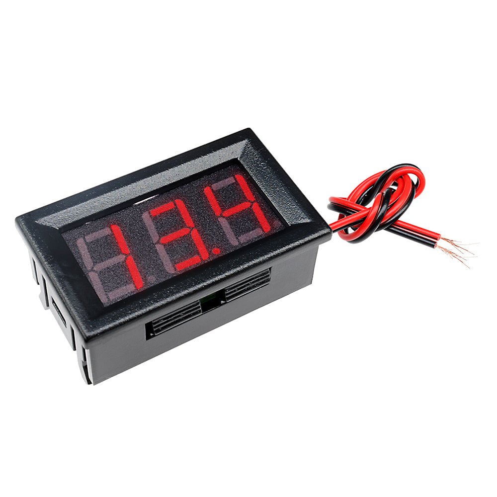
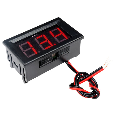 Translation missing: en.products.product.regular_price $5.99{"id":4419938418759,"title":"Arduino 2A H-Bridge Dual Channel DC Motor Driver Shield Module L298NH Than L298P","handle":"replace-l298p-for-arduino-uno-r3-dual-channel-dc-motor-driver-shield-expansion-board-l298nh-module-driving-module-mega2560-one","description":"\u003cdiv\u003e\n\u003cwidget data-widget-type=\"customText\" id=\"33684419\" title=\"Head\" type=\"custom\"\u003e\u003c\/widget\u003e \r \u003cp\u003e\u003cspan style=\"font-size: 16.0px;font-family: trebuchet ms;\"\u003e \u003c\/span\u003e\u003c\/p\u003e \r \u003cdiv\u003e \r \u003cspan style=\"font-size: 16.0px;font-family: trebuchet ms;\"\u003e \u003c\/span\u003e \r \u003cp\u003e\u003cimg src=\"https:\/\/ae01.alicdn.com\/kf\/HTB12JMgilsmBKNjSZFsq6yXSVXaS.jpg\"\u003e\u003c\/p\u003e \r \u003c\/div\u003e \r \u003cdiv\u003e \r \u003cp\u003e\u003cbr\u003e\u003c\/p\u003e \r \u003c\/div\u003e \r \u003cdiv\u003e \r \u003cspan style=\"font-size: 16.0px;font-family: trebuchet ms;\"\u003e \u003c\/span\u003e \r \u003c\/div\u003e \r \u003cdiv\u003e \r \u003cspan style=\"font-size: 16.0px;font-family: trebuchet ms;\"\u003e\u003cspan style=\"font-size: 16.0px;font-family: trebuchet ms;\"\u003eThe Motor Shield is based on the L298NH, which is a dual full-bridge driver designed to drive inductive loads such as relays, solenoids, DC and stepping motors. It lets you drive two DC motors with your for arduino board, controlling the speed and direction of each one independently. You can also measure the motor current absorption of each motor, among other features. \u003c\/span\u003e\u003c\/span\u003e \r \u003c\/div\u003e \r \u003cdiv\u003e \r \u003cspan style=\"font-size: 16.0px;font-family: trebuchet ms;\"\u003e\u003cspan style=\"font-size: 16.0px;font-family: trebuchet ms;\"\u003e•You can find in the Getting Started section all the information you need to configure your board, use the for arduino Software (IDE), and start tinker with coding and electronics. \u003c\/span\u003e\u003c\/span\u003e \r \u003c\/div\u003e \r \u003cdiv\u003e \r \u003cspan style=\"font-size: 16.0px;font-family: trebuchet ms;\"\u003e \u003c\/span\u003e \r \u003c\/div\u003e \r \u003cdiv\u003e \r \u003cspan style=\"font-size: 16.0px;font-family: trebuchet ms;color: #ff6600;\"\u003e\u003cspan style=\"font-size: 16.0px;font-family: trebuchet ms;color: #ff6600;\"\u003e\u003cstrong\u003eTechnical specs\u003c\/strong\u003e\u003c\/span\u003e\u003c\/span\u003e \r \u003c\/div\u003e \r \u003cdiv\u003e \r \u003cspan style=\"font-size: 16.0px;\"\u003e\u003cspan style=\"font-family: trebuchet ms , helvetica , sans-serif;\"\u003e\u003cspan style=\"font-size: 16.0px;font-family: trebuchet ms;\"\u003eOperating Voltage\u003c\/span\u003e\u003cspan style=\"font-size: 16.0px;font-family: trebuchet ms;\"\u003e \u003c\/span\u003e\u003cspan style=\"font-size: 16.0px;font-family: trebuchet ms;\"\u003e5V to 12V\u003c\/span\u003e\u003c\/span\u003e\u003c\/span\u003e \r \u003c\/div\u003e \r \u003cdiv\u003e \r \u003cspan style=\"font-size: 16.0px;\"\u003e\u003cspan style=\"font-family: trebuchet ms , helvetica , sans-serif;\"\u003e\u003cspan style=\"font-size: 16.0px;font-family: trebuchet ms;\"\u003eMotor controller \u003c\/span\u003e\u003cspan style=\"font-size: 16.0px;font-family: trebuchet ms;\"\u003e \u003c\/span\u003e\u003cspan style=\"font-size: 16.0px;font-family: trebuchet ms;\"\u003eL298HN, Drives 2 DC motors or 1 stepper motor\u003c\/span\u003e\u003c\/span\u003e\u003c\/span\u003e \r \u003c\/div\u003e \r \u003cdiv\u003e \r \u003cspan style=\"font-size: 16.0px;\"\u003e\u003cspan style=\"font-family: trebuchet ms , helvetica , sans-serif;\"\u003e\u003cspan style=\"font-size: 16.0px;font-family: trebuchet ms;\"\u003eMax current\u003c\/span\u003e\u003cspan style=\"font-size: 16.0px;font-family: trebuchet ms;\"\u003e \u003c\/span\u003e\u003cspan style=\"font-size: 16.0px;font-family: trebuchet ms;\"\u003e2A per channel or 4A max (with external power supply)\u003c\/span\u003e\u003c\/span\u003e\u003c\/span\u003e \r \u003c\/div\u003e \r \u003cdiv\u003e \r \u003cspan style=\"font-size: 16.0px;\"\u003e\u003cspan style=\"font-family: trebuchet ms , helvetica , sans-serif;\"\u003e\u003cspan style=\"font-size: 16.0px;font-family: trebuchet ms;\"\u003eCurrent sensing\u003c\/span\u003e\u003cspan style=\"font-size: 16.0px;font-family: trebuchet ms;\"\u003e \u003c\/span\u003e\u003cspan style=\"font-size: 16.0px;font-family: trebuchet ms;\"\u003e1.65V\/A\u003c\/span\u003e\u003c\/span\u003e\u003c\/span\u003e \r \u003c\/div\u003e \r \u003cdiv\u003e \r \u003cspan style=\"font-size: 16.0px;font-family: trebuchet ms;\"\u003e\u003cspan style=\"font-size: 16.0px;font-family: trebuchet ms;\"\u003e\u003cspan style=\"font-size: 16.0px;font-family: trebuchet ms;\"\u003eFree running stop and brake function\u003c\/span\u003e\u003c\/span\u003e\u003c\/span\u003e \r \u003c\/div\u003e \r \u003cdiv\u003e \r \u003cspan style=\"font-size: 16.0px;font-family: trebuchet ms;\"\u003e \u003c\/span\u003e \r \u003c\/div\u003e \r \u003cdiv\u003e \r \u003cspan style=\"font-size: 16.0px;font-family: trebuchet ms;color: #ff6600;\"\u003e\u003cspan style=\"font-size: 16.0px;font-family: trebuchet ms;color: #ff6600;\"\u003e\u003cstrong\u003ePower\u003c\/strong\u003e\u003c\/span\u003e\u003c\/span\u003e \r \u003c\/div\u003e \r \u003cdiv\u003e \r \u003cspan style=\"font-size: 16.0px;font-family: trebuchet ms;\"\u003e \u003c\/span\u003e \r \u003c\/div\u003e \r \u003cdiv\u003e \r \u003cspan style=\"font-size: 16.0px;font-family: trebuchet ms;\"\u003e\u003cspan style=\"font-size: 16.0px;font-family: trebuchet ms;\"\u003eThe Motor Shield must be powered only by an external power supply. Because the L298HN IC mounted on the shield has two separate power connections, one for the logic and one for the motor supply driver. The required motor current often exceeds the maximum USB current rating.\u003c\/span\u003e\u003c\/span\u003e \r \u003c\/div\u003e \r \u003cdiv\u003e \r \u003cspan style=\"font-size: 16.0px;font-family: trebuchet ms;\"\u003e\u003cspan style=\"font-size: 16.0px;font-family: trebuchet ms;\"\u003eExternal (non-USB) power can come either from an AC-to-DC adapter (wall-wart) or battery. The adapter can be connected by plugging a 2.1mm center-positive plug into the for arduino 's board power jack on which the motor shield is mounted or by connecting the wires that lead the power supply to the Vin and GND screw terminals, taking care to respect the polarities.\u003c\/span\u003e\u003c\/span\u003e \r \u003c\/div\u003e \r \u003cdiv\u003e \r \u003cspan style=\"font-size: 16.0px;font-family: trebuchet ms;\"\u003e\u003cspan style=\"font-size: 16.0px;font-family: trebuchet ms;\"\u003eTo avoid possible damage to the for arduino board on which the shield is mounted, we reccomend using an external power supply that provides a voltage between 7 and 12V. If your motor require more than 9V we recommend that you separate the power lines of the shield and the for arduino board on which the shield is mounted. This is possible by cutting the \"Vin Connect\" jumper placed on the back side of the shield. The absolute limit for the Vin at the screw terminals is 18V.\u003c\/span\u003e\u003c\/span\u003e \r \u003c\/div\u003e \r \u003cdiv\u003e \r \u003cspan style=\"font-size: 16.0px;font-family: trebuchet ms;\"\u003e\u003cspan style=\"font-size: 16.0px;font-family: trebuchet ms;\"\u003eThe shield can supply 2 amperes per channel, for a total of 4 amperes maximum. \u003c\/span\u003e\u003c\/span\u003e \r \u003c\/div\u003e \r \u003cdiv\u003e \r \u003cspan style=\"font-size: 16.0px;font-family: trebuchet ms;\"\u003e \u003c\/span\u003e \r \u003c\/div\u003e \r \u003cdiv\u003e \r \u003cspan style=\"font-size: 16.0px;font-family: trebuchet ms;color: #ff6600;\"\u003e\u003cspan style=\"font-size: 16.0px;font-family: trebuchet ms;color: #ff6600;\"\u003e\u003cstrong\u003eInput and Output\u003c\/strong\u003e\u003c\/span\u003e\u003c\/span\u003e \r \u003c\/div\u003e \r \u003cdiv\u003e \r \u003cspan style=\"font-size: 16.0px;font-family: trebuchet ms;\"\u003e \u003c\/span\u003e \r \u003c\/div\u003e \r \u003cdiv\u003e \r \u003cspan style=\"font-size: 16.0px;font-family: trebuchet ms;\"\u003e\u003cspan style=\"font-size: 16.0px;font-family: trebuchet ms;\"\u003eThis shield has two separate channels, called A and B, that each use 4 of the for arduino pins to drive or sense the motor. In total there are 8 pins in use on this shield. You can use each channel separately to drive two DC motors or combine them to drive one bipolar stepper motor. The shield's pins, divided by channel are shown in the table below: \u003c\/span\u003e\u003c\/span\u003e \r \u003c\/div\u003e \r \u003cdiv\u003e \r \u003cspan style=\"font-size: 16.0px;font-family: trebuchet ms;\"\u003e \u003c\/span\u003e \r \u003c\/div\u003e \r \u003cdiv\u003e \r \u003cspan style=\"font-size: 16.0px;\"\u003e\u003cspan style=\"font-family: trebuchet ms , helvetica , sans-serif;\"\u003e\u003cspan style=\"font-size: 16.0px;font-family: trebuchet ms;\"\u003eFunction \u003c\/span\u003e\u003cspan style=\"font-size: 16.0px;font-family: trebuchet ms;\"\u003e \u003c\/span\u003e\u003cspan style=\"font-size: 16.0px;font-family: trebuchet ms;\"\u003epins per Ch. A\u003c\/span\u003e\u003cspan style=\"font-size: 16.0px;font-family: trebuchet ms;\"\u003e \u003c\/span\u003e\u003cspan style=\"font-size: 16.0px;font-family: trebuchet ms;\"\u003epins per Ch. B\u003c\/span\u003e\u003c\/span\u003e\u003c\/span\u003e \r \u003c\/div\u003e \r \u003cdiv\u003e \r \u003cspan style=\"font-size: 16.0px;\"\u003e\u003cspan style=\"font-family: trebuchet ms , helvetica , sans-serif;\"\u003e\u003cspan style=\"font-size: 16.0px;font-family: trebuchet ms;\"\u003eDirection\u003c\/span\u003e\u003cspan style=\"font-size: 16.0px;font-family: trebuchet ms;\"\u003e \u003c\/span\u003e\u003cspan style=\"font-size: 16.0px;font-family: trebuchet ms;\"\u003eD12\u003c\/span\u003e\u003cspan style=\"font-size: 16.0px;font-family: trebuchet ms;\"\u003e \u003c\/span\u003e\u003cspan style=\"font-size: 16.0px;font-family: trebuchet ms;\"\u003eD13\u003c\/span\u003e\u003c\/span\u003e\u003c\/span\u003e \r \u003c\/div\u003e \r \u003cdiv\u003e \r \u003cspan style=\"font-size: 16.0px;\"\u003e\u003cspan style=\"font-family: trebuchet ms , helvetica , sans-serif;\"\u003e\u003cspan style=\"font-size: 16.0px;font-family: trebuchet ms;\"\u003ePWM\u003c\/span\u003e\u003cspan style=\"font-size: 16.0px;font-family: trebuchet ms;\"\u003e \u003c\/span\u003e\u003cspan style=\"font-size: 16.0px;font-family: trebuchet ms;\"\u003eD3\u003c\/span\u003e\u003cspan style=\"font-size: 16.0px;font-family: trebuchet ms;\"\u003e \u003c\/span\u003e\u003cspan style=\"font-size: 16.0px;font-family: trebuchet ms;\"\u003eD11\u003c\/span\u003e\u003c\/span\u003e\u003c\/span\u003e \r \u003c\/div\u003e \r \u003cdiv\u003e \r \u003cspan style=\"font-size: 16.0px;\"\u003e\u003cspan style=\"font-family: trebuchet ms , helvetica , sans-serif;\"\u003e\u003cspan style=\"font-size: 16.0px;font-family: trebuchet ms;\"\u003eBrake\u003c\/span\u003e\u003cspan style=\"font-size: 16.0px;font-family: trebuchet ms;\"\u003e \u003c\/span\u003e\u003cspan style=\"font-size: 16.0px;font-family: trebuchet ms;\"\u003eD9\u003c\/span\u003e\u003cspan style=\"font-size: 16.0px;font-family: trebuchet ms;\"\u003e \u003c\/span\u003e\u003cspan style=\"font-size: 16.0px;font-family: trebuchet ms;\"\u003eD8\u003c\/span\u003e\u003c\/span\u003e\u003c\/span\u003e \r \u003c\/div\u003e \r \u003cdiv\u003e \r \u003cspan style=\"font-size: 16.0px;\"\u003e\u003cspan style=\"font-family: trebuchet ms , helvetica , sans-serif;\"\u003e\u003cspan style=\"font-size: 16.0px;font-family: trebuchet ms;\"\u003eCurrent Sensing\u003c\/span\u003e\u003cspan style=\"font-size: 16.0px;font-family: trebuchet ms;\"\u003e \u003c\/span\u003e\u003cspan style=\"font-size: 16.0px;font-family: trebuchet ms;\"\u003eA0 \u003c\/span\u003e\u003cspan style=\"font-size: 16.0px;font-family: trebuchet ms;\"\u003e \u003c\/span\u003e\u003cspan style=\"font-size: 16.0px;font-family: trebuchet ms;\"\u003eA1\u003c\/span\u003e\u003c\/span\u003e\u003c\/span\u003e \r \u003c\/div\u003e \r \u003cdiv\u003e \r \u003cspan style=\"font-size: 16.0px;font-family: trebuchet ms;\"\u003e \u003c\/span\u003e \r \u003c\/div\u003e \r \u003cdiv\u003e \r \u003cspan style=\"font-size: 16.0px;font-family: trebuchet ms;\"\u003e\u003cspan style=\"font-size: 16.0px;font-family: trebuchet ms;\"\u003eIf you don't need the Brake and the Current Sensing and you also need more pins for your application you can disable this features by cutting the respective jumpers on the back side of the shield. \u003c\/span\u003e\u003c\/span\u003e \r \u003c\/div\u003e \r \u003cdiv\u003e \r \u003cspan style=\"font-size: 16.0px;font-family: trebuchet ms;\"\u003e \u003c\/span\u003e \r \u003c\/div\u003e \r \u003cdiv\u003e \r \u003cspan style=\"font-size: 16.0px;font-family: trebuchet ms;color: #ff6600;\"\u003e\u003cspan style=\"font-size: 16.0px;font-family: trebuchet ms;color: #ff6600;\"\u003e\u003cstrong\u003eMotors Connection\u003c\/strong\u003e\u003c\/span\u003e\u003c\/span\u003e \r \u003c\/div\u003e \r \u003cdiv\u003e \r \u003cspan style=\"font-size: 16.0px;font-family: trebuchet ms;\"\u003e\u003cspan style=\"font-size: 16.0px;font-family: trebuchet ms;\"\u003eBrushed DC motor. You can drive two Brushed DC motors by connecting the two wires of each one in the (+) and (-) screw terminals for each channel A and B. In this way you can control its direction by setting HIGH or LOW the DIR A and DIR B pins, you can control the speed by varying the PWM A and PWM B duty cycle values. The Brake A and Brake B pins, if set HIGH, will effectively brake the DC motors rather than let them slow down by cutting the power. You can measure the current going through the DC motor by reading the SNS0 and SNS1 pins. On each channel will be a voltage proportional to the measured current, which can be read as a normal analog input, through the function analogRead() on the analog input A0 and A1. For your convenience it is calibrated to be 3.3V when the channel is delivering its maximum possible current, that is 2A. \u003c\/span\u003e\u003c\/span\u003e \r \u003c\/div\u003e \r \u003cdiv\u003e \r \u003cspan style=\"font-size: 16.0px;font-family: trebuchet ms;\"\u003e \u003c\/span\u003e \r \u003c\/div\u003e \r \u003cdiv\u003e \r \u003cspan style=\"font-size: 16.0px;font-family: trebuchet ms;\"\u003e \u003c\/span\u003e \r \u003c\/div\u003e \r \u003cdiv\u003e \r \u003cspan style=\"font-size: 16.0px;font-family: trebuchet ms;\"\u003e \u003c\/span\u003e \r \u003c\/div\u003e \r \u003cdiv\u003e \r \u003cspan style=\"font-size: 16.0px;font-family: trebuchet ms;\"\u003e \u003c\/span\u003e \r \u003c\/div\u003e \r \u003cdiv\u003e \r \u003cspan style=\"font-size: 16.0px;font-family: trebuchet ms;color: #ff6600;\"\u003e\u003cstrong\u003e \u003c\/strong\u003e\u003c\/span\u003e \r \u003cspan style=\"font-size: 16.0px;font-family: trebuchet ms;color: #ff6600;\"\u003e\u003cspan style=\"font-size: 16.0px;font-family: trebuchet ms;color: #ff6600;\"\u003e\u003cstrong\u003ePackage Included:\u003c\/strong\u003e\u003c\/span\u003e\u003c\/span\u003e \r \u003c\/div\u003e \r \u003cdiv\u003e \r \u003cspan style=\"font-size: 16.0px;font-family: trebuchet ms;\"\u003e \u003c\/span\u003e \r \u003c\/div\u003e \r \u003cdiv\u003e \r \u003cspan style=\"font-size: 16.0px;font-family: trebuchet ms;\"\u003e 1 x L298NH Dual Channel DC Motor Driver Shield Board\u003c\/span\u003e \r \u003c\/div\u003e \r \u003cp\u003e\u003cspan style=\"font-size: 16.0px;font-family: trebuchet ms;\"\u003e \u003c\/span\u003e\u003c\/p\u003e \r \u003cp\u003e\u003cspan style=\"font-size: 16.0px;font-family: trebuchet ms;\"\u003e \u003c\/span\u003e\u003c\/p\u003e \r \u003cspan style=\"font-size: 16.0px;font-family: trebuchet ms;\"\u003e \u003cp\u003e\u003cimg src=\"https:\/\/ae01.alicdn.com\/kf\/HTB1VXjubuUXBuNjt_a0q6AysXXaA.jpg\"\u003e\u003c\/p\u003e\n\u003cp\u003e \u003c\/p\u003e\n\u003cp\u003e\u003cimg style=\"width: 1000.0px;\" src=\"https:\/\/ae01.alicdn.com\/kf\/HTB1acVFa6vuK1Rjy0Faq6x2aVXaR.jpg\"\u003e\u003c\/p\u003e\n\u003cp\u003e\u003cimg style=\"width: 1000.0px;\" src=\"https:\/\/ae01.alicdn.com\/kf\/HTB14yJHa.rrK1RkSne1q6ArVVXaJ.jpg\"\u003e\u003c\/p\u003e\n\u003cp\u003e\u003cbr\u003e\u003c\/p\u003e\n\u003cp\u003e\u003cimg style=\"width: 1000.0px;\" src=\"https:\/\/ae01.alicdn.com\/kf\/HTB1VvpAa.vrK1RjSszfq6xJNVXat.jpg\"\u003e\u003c\/p\u003e\n\u003cp\u003e\u003cimg style=\"width: 1000.0px;\" src=\"https:\/\/ae01.alicdn.com\/kf\/HTB1yj5TaPLuK1Rjy0Fhq6xpdFXa6.jpg\"\u003e\u003c\/p\u003e\n\u003cp\u003e\u003cimg style=\"width: 1000.0px;\" src=\"https:\/\/ae01.alicdn.com\/kf\/HTB1WhJCa5DxK1Rjy1zcq6yGeXXai.jpg\"\u003e\u003c\/p\u003e\n\u003cp\u003e \u003c\/p\u003e\n\u003cp\u003e\u003cimg src=\"https:\/\/ae01.alicdn.com\/kf\/HTB1Hc.uimcqBKNjSZFgq6x_kXXaq.jpg\"\u003e\u003c\/p\u003e\n\u003cp\u003e \u003c\/p\u003e\n\u003cp\u003e \r \u003cwidget data-widget-type=\"customText\" id=\"24006699\" title=\"Related\" type=\"custom\"\u003e\u003c\/widget\u003e \u003c\/p\u003e\u003c\/span\u003e \r \u003cp\u003e\u003c\/p\u003e \r \u003cp\u003e\u003cspan style=\"font-size: 16.0px;font-family: trebuchet ms;\"\u003e \u003c\/span\u003e\u003c\/p\u003e \u003cscript\u003ewindow.adminAccountId=227552571;\u003c\/script\u003e \u003c\/div\u003e","published_at":"2019-12-27T16:28:18+08:00","created_at":"2019-12-27T16:28:30+08:00","vendor":"diymore","type":"Integrated Circuits","tags":[],"price":899,"price_min":899,"price_max":899,"available":true,"price_varies":false,"compare_at_price":null,"compare_at_price_min":0,"compare_at_price_max":0,"compare_at_price_varies":false,"variants":[{"id":31582607409223,"title":"Default Title","option1":"Default Title","option2":null,"option3":null,"sku":"180030","requires_shipping":true,"taxable":true,"featured_image":null,"available":true,"name":"Arduino 2A H-Bridge Dual Channel DC Motor Driver Shield Module L298NH Than L298P","public_title":null,"options":["Default Title"],"price":899,"weight":30,"compare_at_price":null,"inventory_management":null,"barcode":"","requires_selling_plan":false,"selling_plan_allocations":[],"quantity_rule":{"min":1,"max":null,"increment":1}}],"images":["\/\/www.diymore.cc\/cdn\/shop\/products\/Replace-L298P-For-Arduino-UNO-R3-Dual-Channel-DC-Motor-Driver-Shield-Expansion-Board-L298NH-Module_259.jpg?v=1588697940","\/\/www.diymore.cc\/cdn\/shop\/products\/Replace-L298P-For-Arduino-UNO-R3-Dual-Channel-DC-Motor-Driver-Shield-Expansion-Board-L298NH-Module_63b77384-930b-4e89-8b62-17bdb7ff23c5_644.jpg?v=1588697940","\/\/www.diymore.cc\/cdn\/shop\/products\/Replace-L298P-For-Arduino-UNO-R3-Dual-Channel-DC-Motor-Driver-Shield-Expansion-Board-L298NH-Module_0a80a83c-dc2f-460c-a034-768bd412d88c_731.jpg?v=1588697940","\/\/www.diymore.cc\/cdn\/shop\/products\/Replace-L298P-For-Arduino-UNO-R3-Dual-Channel-DC-Motor-Driver-Shield-Expansion-Board-L298NH-Module_10e0ead5-7c58-4cd0-9dbc-9e26210641df_203.jpg?v=1588697940","\/\/www.diymore.cc\/cdn\/shop\/products\/Replace-L298P-For-Arduino-UNO-R3-Dual-Channel-DC-Motor-Driver-Shield-Expansion-Board-L298NH-Module_c95cb3f4-de34-4a9e-b289-07a336bce0ef_828.jpg?v=1588697940"],"featured_image":"\/\/www.diymore.cc\/cdn\/shop\/products\/Replace-L298P-For-Arduino-UNO-R3-Dual-Channel-DC-Motor-Driver-Shield-Expansion-Board-L298NH-Module_259.jpg?v=1588697940","options":["Title"],"media":[{"alt":"Replace L298P For Arduino Uno R3 Dual Channel Dc Motor Driver Shield Expansion Board L298Nh Module","id":6682319224903,"position":1,"preview_image":{"aspect_ratio":1.0,"height":1000,"width":1000,"src":"\/\/www.diymore.cc\/cdn\/shop\/products\/Replace-L298P-For-Arduino-UNO-R3-Dual-Channel-DC-Motor-Driver-Shield-Expansion-Board-L298NH-Module_259.jpg?v=1588697940"},"aspect_ratio":1.0,"height":1000,"media_type":"image","src":"\/\/www.diymore.cc\/cdn\/shop\/products\/Replace-L298P-For-Arduino-UNO-R3-Dual-Channel-DC-Motor-Driver-Shield-Expansion-Board-L298NH-Module_259.jpg?v=1588697940","width":1000},{"alt":"Replace L298P For Arduino Uno R3 Dual Channel Dc Motor Driver Shield Expansion Board L298Nh Module","id":6682319355975,"position":2,"preview_image":{"aspect_ratio":1.0,"height":1000,"width":1000,"src":"\/\/www.diymore.cc\/cdn\/shop\/products\/Replace-L298P-For-Arduino-UNO-R3-Dual-Channel-DC-Motor-Driver-Shield-Expansion-Board-L298NH-Module_63b77384-930b-4e89-8b62-17bdb7ff23c5_644.jpg?v=1588697940"},"aspect_ratio":1.0,"height":1000,"media_type":"image","src":"\/\/www.diymore.cc\/cdn\/shop\/products\/Replace-L298P-For-Arduino-UNO-R3-Dual-Channel-DC-Motor-Driver-Shield-Expansion-Board-L298NH-Module_63b77384-930b-4e89-8b62-17bdb7ff23c5_644.jpg?v=1588697940","width":1000},{"alt":"Replace L298P For Arduino Uno R3 Dual Channel Dc Motor Driver Shield Expansion Board L298Nh Module","id":6682319585351,"position":3,"preview_image":{"aspect_ratio":1.0,"height":1000,"width":1000,"src":"\/\/www.diymore.cc\/cdn\/shop\/products\/Replace-L298P-For-Arduino-UNO-R3-Dual-Channel-DC-Motor-Driver-Shield-Expansion-Board-L298NH-Module_0a80a83c-dc2f-460c-a034-768bd412d88c_731.jpg?v=1588697940"},"aspect_ratio":1.0,"height":1000,"media_type":"image","src":"\/\/www.diymore.cc\/cdn\/shop\/products\/Replace-L298P-For-Arduino-UNO-R3-Dual-Channel-DC-Motor-Driver-Shield-Expansion-Board-L298NH-Module_0a80a83c-dc2f-460c-a034-768bd412d88c_731.jpg?v=1588697940","width":1000},{"alt":"Replace L298P For Arduino Uno R3 Dual Channel Dc Motor Driver Shield Expansion Board L298Nh Module","id":6682319716423,"position":4,"preview_image":{"aspect_ratio":1.0,"height":1000,"width":1000,"src":"\/\/www.diymore.cc\/cdn\/shop\/products\/Replace-L298P-For-Arduino-UNO-R3-Dual-Channel-DC-Motor-Driver-Shield-Expansion-Board-L298NH-Module_10e0ead5-7c58-4cd0-9dbc-9e26210641df_203.jpg?v=1588697940"},"aspect_ratio":1.0,"height":1000,"media_type":"image","src":"\/\/www.diymore.cc\/cdn\/shop\/products\/Replace-L298P-For-Arduino-UNO-R3-Dual-Channel-DC-Motor-Driver-Shield-Expansion-Board-L298NH-Module_10e0ead5-7c58-4cd0-9dbc-9e26210641df_203.jpg?v=1588697940","width":1000},{"alt":"Replace L298P For Arduino Uno R3 Dual Channel Dc Motor Driver Shield Expansion Board L298Nh Module","id":6682319781959,"position":5,"preview_image":{"aspect_ratio":1.0,"height":1000,"width":1000,"src":"\/\/www.diymore.cc\/cdn\/shop\/products\/Replace-L298P-For-Arduino-UNO-R3-Dual-Channel-DC-Motor-Driver-Shield-Expansion-Board-L298NH-Module_c95cb3f4-de34-4a9e-b289-07a336bce0ef_828.jpg?v=1588697940"},"aspect_ratio":1.0,"height":1000,"media_type":"image","src":"\/\/www.diymore.cc\/cdn\/shop\/products\/Replace-L298P-For-Arduino-UNO-R3-Dual-Channel-DC-Motor-Driver-Shield-Expansion-Board-L298NH-Module_c95cb3f4-de34-4a9e-b289-07a336bce0ef_828.jpg?v=1588697940","width":1000}],"requires_selling_plan":false,"selling_plan_groups":[],"content":"\u003cdiv\u003e\n\u003cwidget data-widget-type=\"customText\" id=\"33684419\" title=\"Head\" type=\"custom\"\u003e\u003c\/widget\u003e \r \u003cp\u003e\u003cspan style=\"font-size: 16.0px;font-family: trebuchet ms;\"\u003e \u003c\/span\u003e\u003c\/p\u003e \r \u003cdiv\u003e \r \u003cspan style=\"font-size: 16.0px;font-family: trebuchet ms;\"\u003e \u003c\/span\u003e \r \u003cp\u003e\u003cimg src=\"https:\/\/ae01.alicdn.com\/kf\/HTB12JMgilsmBKNjSZFsq6yXSVXaS.jpg\"\u003e\u003c\/p\u003e \r \u003c\/div\u003e \r \u003cdiv\u003e \r \u003cp\u003e\u003cbr\u003e\u003c\/p\u003e \r \u003c\/div\u003e \r \u003cdiv\u003e \r \u003cspan style=\"font-size: 16.0px;font-family: trebuchet ms;\"\u003e \u003c\/span\u003e \r \u003c\/div\u003e \r \u003cdiv\u003e \r \u003cspan style=\"font-size: 16.0px;font-family: trebuchet ms;\"\u003e\u003cspan style=\"font-size: 16.0px;font-family: trebuchet ms;\"\u003eThe Motor Shield is based on the L298NH, which is a dual full-bridge driver designed to drive inductive loads such as relays, solenoids, DC and stepping motors. It lets you drive two DC motors with your for arduino board, controlling the speed and direction of each one independently. You can also measure the motor current absorption of each motor, among other features. \u003c\/span\u003e\u003c\/span\u003e \r \u003c\/div\u003e \r \u003cdiv\u003e \r \u003cspan style=\"font-size: 16.0px;font-family: trebuchet ms;\"\u003e\u003cspan style=\"font-size: 16.0px;font-family: trebuchet ms;\"\u003e•You can find in the Getting Started section all the information you need to configure your board, use the for arduino Software (IDE), and start tinker with coding and electronics. \u003c\/span\u003e\u003c\/span\u003e \r \u003c\/div\u003e \r \u003cdiv\u003e \r \u003cspan style=\"font-size: 16.0px;font-family: trebuchet ms;\"\u003e \u003c\/span\u003e \r \u003c\/div\u003e \r \u003cdiv\u003e \r \u003cspan style=\"font-size: 16.0px;font-family: trebuchet ms;color: #ff6600;\"\u003e\u003cspan style=\"font-size: 16.0px;font-family: trebuchet ms;color: #ff6600;\"\u003e\u003cstrong\u003eTechnical specs\u003c\/strong\u003e\u003c\/span\u003e\u003c\/span\u003e \r \u003c\/div\u003e \r \u003cdiv\u003e \r \u003cspan style=\"font-size: 16.0px;\"\u003e\u003cspan style=\"font-family: trebuchet ms , helvetica , sans-serif;\"\u003e\u003cspan style=\"font-size: 16.0px;font-family: trebuchet ms;\"\u003eOperating Voltage\u003c\/span\u003e\u003cspan style=\"font-size: 16.0px;font-family: trebuchet ms;\"\u003e \u003c\/span\u003e\u003cspan style=\"font-size: 16.0px;font-family: trebuchet ms;\"\u003e5V to 12V\u003c\/span\u003e\u003c\/span\u003e\u003c\/span\u003e \r \u003c\/div\u003e \r \u003cdiv\u003e \r \u003cspan style=\"font-size: 16.0px;\"\u003e\u003cspan style=\"font-family: trebuchet ms , helvetica , sans-serif;\"\u003e\u003cspan style=\"font-size: 16.0px;font-family: trebuchet ms;\"\u003eMotor controller \u003c\/span\u003e\u003cspan style=\"font-size: 16.0px;font-family: trebuchet ms;\"\u003e \u003c\/span\u003e\u003cspan style=\"font-size: 16.0px;font-family: trebuchet ms;\"\u003eL298HN, Drives 2 DC motors or 1 stepper motor\u003c\/span\u003e\u003c\/span\u003e\u003c\/span\u003e \r \u003c\/div\u003e \r \u003cdiv\u003e \r \u003cspan style=\"font-size: 16.0px;\"\u003e\u003cspan style=\"font-family: trebuchet ms , helvetica , sans-serif;\"\u003e\u003cspan style=\"font-size: 16.0px;font-family: trebuchet ms;\"\u003eMax current\u003c\/span\u003e\u003cspan style=\"font-size: 16.0px;font-family: trebuchet ms;\"\u003e \u003c\/span\u003e\u003cspan style=\"font-size: 16.0px;font-family: trebuchet ms;\"\u003e2A per channel or 4A max (with external power supply)\u003c\/span\u003e\u003c\/span\u003e\u003c\/span\u003e \r \u003c\/div\u003e \r \u003cdiv\u003e \r \u003cspan style=\"font-size: 16.0px;\"\u003e\u003cspan style=\"font-family: trebuchet ms , helvetica , sans-serif;\"\u003e\u003cspan style=\"font-size: 16.0px;font-family: trebuchet ms;\"\u003eCurrent sensing\u003c\/span\u003e\u003cspan style=\"font-size: 16.0px;font-family: trebuchet ms;\"\u003e \u003c\/span\u003e\u003cspan style=\"font-size: 16.0px;font-family: trebuchet ms;\"\u003e1.65V\/A\u003c\/span\u003e\u003c\/span\u003e\u003c\/span\u003e \r \u003c\/div\u003e \r \u003cdiv\u003e \r \u003cspan style=\"font-size: 16.0px;font-family: trebuchet ms;\"\u003e\u003cspan style=\"font-size: 16.0px;font-family: trebuchet ms;\"\u003e\u003cspan style=\"font-size: 16.0px;font-family: trebuchet ms;\"\u003eFree running stop and brake function\u003c\/span\u003e\u003c\/span\u003e\u003c\/span\u003e \r \u003c\/div\u003e \r \u003cdiv\u003e \r \u003cspan style=\"font-size: 16.0px;font-family: trebuchet ms;\"\u003e \u003c\/span\u003e \r \u003c\/div\u003e \r \u003cdiv\u003e \r \u003cspan style=\"font-size: 16.0px;font-family: trebuchet ms;color: #ff6600;\"\u003e\u003cspan style=\"font-size: 16.0px;font-family: trebuchet ms;color: #ff6600;\"\u003e\u003cstrong\u003ePower\u003c\/strong\u003e\u003c\/span\u003e\u003c\/span\u003e \r \u003c\/div\u003e \r \u003cdiv\u003e \r \u003cspan style=\"font-size: 16.0px;font-family: trebuchet ms;\"\u003e \u003c\/span\u003e \r \u003c\/div\u003e \r \u003cdiv\u003e \r \u003cspan style=\"font-size: 16.0px;font-family: trebuchet ms;\"\u003e\u003cspan style=\"font-size: 16.0px;font-family: trebuchet ms;\"\u003eThe Motor Shield must be powered only by an external power supply. Because the L298HN IC mounted on the shield has two separate power connections, one for the logic and one for the motor supply driver. The required motor current often exceeds the maximum USB current rating.\u003c\/span\u003e\u003c\/span\u003e \r \u003c\/div\u003e \r \u003cdiv\u003e \r \u003cspan style=\"font-size: 16.0px;font-family: trebuchet ms;\"\u003e\u003cspan style=\"font-size: 16.0px;font-family: trebuchet ms;\"\u003eExternal (non-USB) power can come either from an AC-to-DC adapter (wall-wart) or battery. The adapter can be connected by plugging a 2.1mm center-positive plug into the for arduino 's board power jack on which the motor shield is mounted or by connecting the wires that lead the power supply to the Vin and GND screw terminals, taking care to respect the polarities.\u003c\/span\u003e\u003c\/span\u003e \r \u003c\/div\u003e \r \u003cdiv\u003e \r \u003cspan style=\"font-size: 16.0px;font-family: trebuchet ms;\"\u003e\u003cspan style=\"font-size: 16.0px;font-family: trebuchet ms;\"\u003eTo avoid possible damage to the for arduino board on which the shield is mounted, we reccomend using an external power supply that provides a voltage between 7 and 12V. If your motor require more than 9V we recommend that you separate the power lines of the shield and the for arduino board on which the shield is mounted. This is possible by cutting the \"Vin Connect\" jumper placed on the back side of the shield. The absolute limit for the Vin at the screw terminals is 18V.\u003c\/span\u003e\u003c\/span\u003e \r \u003c\/div\u003e \r \u003cdiv\u003e \r \u003cspan style=\"font-size: 16.0px;font-family: trebuchet ms;\"\u003e\u003cspan style=\"font-size: 16.0px;font-family: trebuchet ms;\"\u003eThe shield can supply 2 amperes per channel, for a total of 4 amperes maximum. \u003c\/span\u003e\u003c\/span\u003e \r \u003c\/div\u003e \r \u003cdiv\u003e \r \u003cspan style=\"font-size: 16.0px;font-family: trebuchet ms;\"\u003e \u003c\/span\u003e \r \u003c\/div\u003e \r \u003cdiv\u003e \r \u003cspan style=\"font-size: 16.0px;font-family: trebuchet ms;color: #ff6600;\"\u003e\u003cspan style=\"font-size: 16.0px;font-family: trebuchet ms;color: #ff6600;\"\u003e\u003cstrong\u003eInput and Output\u003c\/strong\u003e\u003c\/span\u003e\u003c\/span\u003e \r \u003c\/div\u003e \r \u003cdiv\u003e \r \u003cspan style=\"font-size: 16.0px;font-family: trebuchet ms;\"\u003e \u003c\/span\u003e \r \u003c\/div\u003e \r \u003cdiv\u003e \r \u003cspan style=\"font-size: 16.0px;font-family: trebuchet ms;\"\u003e\u003cspan style=\"font-size: 16.0px;font-family: trebuchet ms;\"\u003eThis shield has two separate channels, called A and B, that each use 4 of the for arduino pins to drive or sense the motor. In total there are 8 pins in use on this shield. You can use each channel separately to drive two DC motors or combine them to drive one bipolar stepper motor. The shield's pins, divided by channel are shown in the table below: \u003c\/span\u003e\u003c\/span\u003e \r \u003c\/div\u003e \r \u003cdiv\u003e \r \u003cspan style=\"font-size: 16.0px;font-family: trebuchet ms;\"\u003e \u003c\/span\u003e \r \u003c\/div\u003e \r \u003cdiv\u003e \r \u003cspan style=\"font-size: 16.0px;\"\u003e\u003cspan style=\"font-family: trebuchet ms , helvetica , sans-serif;\"\u003e\u003cspan style=\"font-size: 16.0px;font-family: trebuchet ms;\"\u003eFunction \u003c\/span\u003e\u003cspan style=\"font-size: 16.0px;font-family: trebuchet ms;\"\u003e \u003c\/span\u003e\u003cspan style=\"font-size: 16.0px;font-family: trebuchet ms;\"\u003epins per Ch. A\u003c\/span\u003e\u003cspan style=\"font-size: 16.0px;font-family: trebuchet ms;\"\u003e \u003c\/span\u003e\u003cspan style=\"font-size: 16.0px;font-family: trebuchet ms;\"\u003epins per Ch. B\u003c\/span\u003e\u003c\/span\u003e\u003c\/span\u003e \r \u003c\/div\u003e \r \u003cdiv\u003e \r \u003cspan style=\"font-size: 16.0px;\"\u003e\u003cspan style=\"font-family: trebuchet ms , helvetica , sans-serif;\"\u003e\u003cspan style=\"font-size: 16.0px;font-family: trebuchet ms;\"\u003eDirection\u003c\/span\u003e\u003cspan style=\"font-size: 16.0px;font-family: trebuchet ms;\"\u003e \u003c\/span\u003e\u003cspan style=\"font-size: 16.0px;font-family: trebuchet ms;\"\u003eD12\u003c\/span\u003e\u003cspan style=\"font-size: 16.0px;font-family: trebuchet ms;\"\u003e \u003c\/span\u003e\u003cspan style=\"font-size: 16.0px;font-family: trebuchet ms;\"\u003eD13\u003c\/span\u003e\u003c\/span\u003e\u003c\/span\u003e \r \u003c\/div\u003e \r \u003cdiv\u003e \r \u003cspan style=\"font-size: 16.0px;\"\u003e\u003cspan style=\"font-family: trebuchet ms , helvetica , sans-serif;\"\u003e\u003cspan style=\"font-size: 16.0px;font-family: trebuchet ms;\"\u003ePWM\u003c\/span\u003e\u003cspan style=\"font-size: 16.0px;font-family: trebuchet ms;\"\u003e \u003c\/span\u003e\u003cspan style=\"font-size: 16.0px;font-family: trebuchet ms;\"\u003eD3\u003c\/span\u003e\u003cspan style=\"font-size: 16.0px;font-family: trebuchet ms;\"\u003e \u003c\/span\u003e\u003cspan style=\"font-size: 16.0px;font-family: trebuchet ms;\"\u003eD11\u003c\/span\u003e\u003c\/span\u003e\u003c\/span\u003e \r \u003c\/div\u003e \r \u003cdiv\u003e \r \u003cspan style=\"font-size: 16.0px;\"\u003e\u003cspan style=\"font-family: trebuchet ms , helvetica , sans-serif;\"\u003e\u003cspan style=\"font-size: 16.0px;font-family: trebuchet ms;\"\u003eBrake\u003c\/span\u003e\u003cspan style=\"font-size: 16.0px;font-family: trebuchet ms;\"\u003e \u003c\/span\u003e\u003cspan style=\"font-size: 16.0px;font-family: trebuchet ms;\"\u003eD9\u003c\/span\u003e\u003cspan style=\"font-size: 16.0px;font-family: trebuchet ms;\"\u003e \u003c\/span\u003e\u003cspan style=\"font-size: 16.0px;font-family: trebuchet ms;\"\u003eD8\u003c\/span\u003e\u003c\/span\u003e\u003c\/span\u003e \r \u003c\/div\u003e \r \u003cdiv\u003e \r \u003cspan style=\"font-size: 16.0px;\"\u003e\u003cspan style=\"font-family: trebuchet ms , helvetica , sans-serif;\"\u003e\u003cspan style=\"font-size: 16.0px;font-family: trebuchet ms;\"\u003eCurrent Sensing\u003c\/span\u003e\u003cspan style=\"font-size: 16.0px;font-family: trebuchet ms;\"\u003e \u003c\/span\u003e\u003cspan style=\"font-size: 16.0px;font-family: trebuchet ms;\"\u003eA0 \u003c\/span\u003e\u003cspan style=\"font-size: 16.0px;font-family: trebuchet ms;\"\u003e \u003c\/span\u003e\u003cspan style=\"font-size: 16.0px;font-family: trebuchet ms;\"\u003eA1\u003c\/span\u003e\u003c\/span\u003e\u003c\/span\u003e \r \u003c\/div\u003e \r \u003cdiv\u003e \r \u003cspan style=\"font-size: 16.0px;font-family: trebuchet ms;\"\u003e \u003c\/span\u003e \r \u003c\/div\u003e \r \u003cdiv\u003e \r \u003cspan style=\"font-size: 16.0px;font-family: trebuchet ms;\"\u003e\u003cspan style=\"font-size: 16.0px;font-family: trebuchet ms;\"\u003eIf you don't need the Brake and the Current Sensing and you also need more pins for your application you can disable this features by cutting the respective jumpers on the back side of the shield. \u003c\/span\u003e\u003c\/span\u003e \r \u003c\/div\u003e \r \u003cdiv\u003e \r \u003cspan style=\"font-size: 16.0px;font-family: trebuchet ms;\"\u003e \u003c\/span\u003e \r \u003c\/div\u003e \r \u003cdiv\u003e \r \u003cspan style=\"font-size: 16.0px;font-family: trebuchet ms;color: #ff6600;\"\u003e\u003cspan style=\"font-size: 16.0px;font-family: trebuchet ms;color: #ff6600;\"\u003e\u003cstrong\u003eMotors Connection\u003c\/strong\u003e\u003c\/span\u003e\u003c\/span\u003e \r \u003c\/div\u003e \r \u003cdiv\u003e \r \u003cspan style=\"font-size: 16.0px;font-family: trebuchet ms;\"\u003e\u003cspan style=\"font-size: 16.0px;font-family: trebuchet ms;\"\u003eBrushed DC motor. You can drive two Brushed DC motors by connecting the two wires of each one in the (+) and (-) screw terminals for each channel A and B. In this way you can control its direction by setting HIGH or LOW the DIR A and DIR B pins, you can control the speed by varying the PWM A and PWM B duty cycle values. The Brake A and Brake B pins, if set HIGH, will effectively brake the DC motors rather than let them slow down by cutting the power. You can measure the current going through the DC motor by reading the SNS0 and SNS1 pins. On each channel will be a voltage proportional to the measured current, which can be read as a normal analog input, through the function analogRead() on the analog input A0 and A1. For your convenience it is calibrated to be 3.3V when the channel is delivering its maximum possible current, that is 2A. \u003c\/span\u003e\u003c\/span\u003e \r \u003c\/div\u003e \r \u003cdiv\u003e \r \u003cspan style=\"font-size: 16.0px;font-family: trebuchet ms;\"\u003e \u003c\/span\u003e \r \u003c\/div\u003e \r \u003cdiv\u003e \r \u003cspan style=\"font-size: 16.0px;font-family: trebuchet ms;\"\u003e \u003c\/span\u003e \r \u003c\/div\u003e \r \u003cdiv\u003e \r \u003cspan style=\"font-size: 16.0px;font-family: trebuchet ms;\"\u003e \u003c\/span\u003e \r \u003c\/div\u003e \r \u003cdiv\u003e \r \u003cspan style=\"font-size: 16.0px;font-family: trebuchet ms;\"\u003e \u003c\/span\u003e \r \u003c\/div\u003e \r \u003cdiv\u003e \r \u003cspan style=\"font-size: 16.0px;font-family: trebuchet ms;color: #ff6600;\"\u003e\u003cstrong\u003e \u003c\/strong\u003e\u003c\/span\u003e \r \u003cspan style=\"font-size: 16.0px;font-family: trebuchet ms;color: #ff6600;\"\u003e\u003cspan style=\"font-size: 16.0px;font-family: trebuchet ms;color: #ff6600;\"\u003e\u003cstrong\u003ePackage Included:\u003c\/strong\u003e\u003c\/span\u003e\u003c\/span\u003e \r \u003c\/div\u003e \r \u003cdiv\u003e \r \u003cspan style=\"font-size: 16.0px;font-family: trebuchet ms;\"\u003e \u003c\/span\u003e \r \u003c\/div\u003e \r \u003cdiv\u003e \r \u003cspan style=\"font-size: 16.0px;font-family: trebuchet ms;\"\u003e 1 x L298NH Dual Channel DC Motor Driver Shield Board\u003c\/span\u003e \r \u003c\/div\u003e \r \u003cp\u003e\u003cspan style=\"font-size: 16.0px;font-family: trebuchet ms;\"\u003e \u003c\/span\u003e\u003c\/p\u003e \r \u003cp\u003e\u003cspan style=\"font-size: 16.0px;font-family: trebuchet ms;\"\u003e \u003c\/span\u003e\u003c\/p\u003e \r \u003cspan style=\"font-size: 16.0px;font-family: trebuchet ms;\"\u003e \u003cp\u003e\u003cimg src=\"https:\/\/ae01.alicdn.com\/kf\/HTB1VXjubuUXBuNjt_a0q6AysXXaA.jpg\"\u003e\u003c\/p\u003e\n\u003cp\u003e \u003c\/p\u003e\n\u003cp\u003e\u003cimg style=\"width: 1000.0px;\" src=\"https:\/\/ae01.alicdn.com\/kf\/HTB1acVFa6vuK1Rjy0Faq6x2aVXaR.jpg\"\u003e\u003c\/p\u003e\n\u003cp\u003e\u003cimg style=\"width: 1000.0px;\" src=\"https:\/\/ae01.alicdn.com\/kf\/HTB14yJHa.rrK1RkSne1q6ArVVXaJ.jpg\"\u003e\u003c\/p\u003e\n\u003cp\u003e\u003cbr\u003e\u003c\/p\u003e\n\u003cp\u003e\u003cimg style=\"width: 1000.0px;\" src=\"https:\/\/ae01.alicdn.com\/kf\/HTB1VvpAa.vrK1RjSszfq6xJNVXat.jpg\"\u003e\u003c\/p\u003e\n\u003cp\u003e\u003cimg style=\"width: 1000.0px;\" src=\"https:\/\/ae01.alicdn.com\/kf\/HTB1yj5TaPLuK1Rjy0Fhq6xpdFXa6.jpg\"\u003e\u003c\/p\u003e\n\u003cp\u003e\u003cimg style=\"width: 1000.0px;\" src=\"https:\/\/ae01.alicdn.com\/kf\/HTB1WhJCa5DxK1Rjy1zcq6yGeXXai.jpg\"\u003e\u003c\/p\u003e\n\u003cp\u003e \u003c\/p\u003e\n\u003cp\u003e\u003cimg src=\"https:\/\/ae01.alicdn.com\/kf\/HTB1Hc.uimcqBKNjSZFgq6x_kXXaq.jpg\"\u003e\u003c\/p\u003e\n\u003cp\u003e \u003c\/p\u003e\n\u003cp\u003e \r \u003cwidget data-widget-type=\"customText\" id=\"24006699\" title=\"Related\" type=\"custom\"\u003e\u003c\/widget\u003e \u003c\/p\u003e\u003c\/span\u003e \r \u003cp\u003e\u003c\/p\u003e \r \u003cp\u003e\u003cspan style=\"font-size: 16.0px;font-family: trebuchet ms;\"\u003e \u003c\/span\u003e\u003c\/p\u003e \u003cscript\u003ewindow.adminAccountId=227552571;\u003c\/script\u003e \u003c\/div\u003e"}
 -
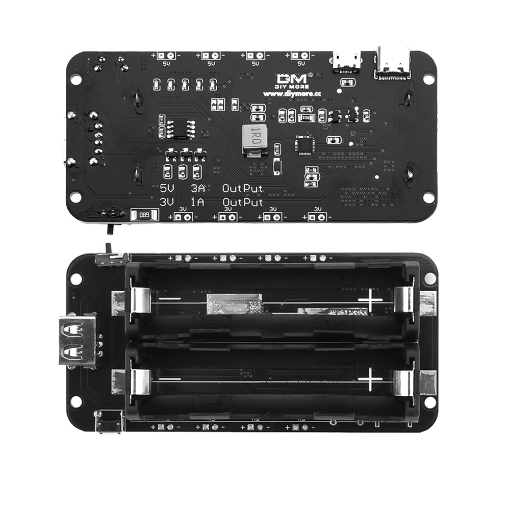
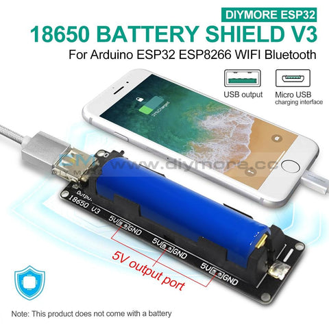 Translation missing: en.products.product.regular_price $5.99{"id":4419938418759,"title":"Arduino 2A H-Bridge Dual Channel DC Motor Driver Shield Module L298NH Than L298P","handle":"replace-l298p-for-arduino-uno-r3-dual-channel-dc-motor-driver-shield-expansion-board-l298nh-module-driving-module-mega2560-one","description":"\u003cdiv\u003e\n\u003cwidget data-widget-type=\"customText\" id=\"33684419\" title=\"Head\" type=\"custom\"\u003e\u003c\/widget\u003e \r \u003cp\u003e\u003cspan style=\"font-size: 16.0px;font-family: trebuchet ms;\"\u003e \u003c\/span\u003e\u003c\/p\u003e \r \u003cdiv\u003e \r \u003cspan style=\"font-size: 16.0px;font-family: trebuchet ms;\"\u003e \u003c\/span\u003e \r \u003cp\u003e\u003cimg src=\"https:\/\/ae01.alicdn.com\/kf\/HTB12JMgilsmBKNjSZFsq6yXSVXaS.jpg\"\u003e\u003c\/p\u003e \r \u003c\/div\u003e \r \u003cdiv\u003e \r \u003cp\u003e\u003cbr\u003e\u003c\/p\u003e \r \u003c\/div\u003e \r \u003cdiv\u003e \r \u003cspan style=\"font-size: 16.0px;font-family: trebuchet ms;\"\u003e \u003c\/span\u003e \r \u003c\/div\u003e \r \u003cdiv\u003e \r \u003cspan style=\"font-size: 16.0px;font-family: trebuchet ms;\"\u003e\u003cspan style=\"font-size: 16.0px;font-family: trebuchet ms;\"\u003eThe Motor Shield is based on the L298NH, which is a dual full-bridge driver designed to drive inductive loads such as relays, solenoids, DC and stepping motors. It lets you drive two DC motors with your for arduino board, controlling the speed and direction of each one independently. You can also measure the motor current absorption of each motor, among other features. \u003c\/span\u003e\u003c\/span\u003e \r \u003c\/div\u003e \r \u003cdiv\u003e \r \u003cspan style=\"font-size: 16.0px;font-family: trebuchet ms;\"\u003e\u003cspan style=\"font-size: 16.0px;font-family: trebuchet ms;\"\u003e•You can find in the Getting Started section all the information you need to configure your board, use the for arduino Software (IDE), and start tinker with coding and electronics. \u003c\/span\u003e\u003c\/span\u003e \r \u003c\/div\u003e \r \u003cdiv\u003e \r \u003cspan style=\"font-size: 16.0px;font-family: trebuchet ms;\"\u003e \u003c\/span\u003e \r \u003c\/div\u003e \r \u003cdiv\u003e \r \u003cspan style=\"font-size: 16.0px;font-family: trebuchet ms;color: #ff6600;\"\u003e\u003cspan style=\"font-size: 16.0px;font-family: trebuchet ms;color: #ff6600;\"\u003e\u003cstrong\u003eTechnical specs\u003c\/strong\u003e\u003c\/span\u003e\u003c\/span\u003e \r \u003c\/div\u003e \r \u003cdiv\u003e \r \u003cspan style=\"font-size: 16.0px;\"\u003e\u003cspan style=\"font-family: trebuchet ms , helvetica , sans-serif;\"\u003e\u003cspan style=\"font-size: 16.0px;font-family: trebuchet ms;\"\u003eOperating Voltage\u003c\/span\u003e\u003cspan style=\"font-size: 16.0px;font-family: trebuchet ms;\"\u003e \u003c\/span\u003e\u003cspan style=\"font-size: 16.0px;font-family: trebuchet ms;\"\u003e5V to 12V\u003c\/span\u003e\u003c\/span\u003e\u003c\/span\u003e \r \u003c\/div\u003e \r \u003cdiv\u003e \r \u003cspan style=\"font-size: 16.0px;\"\u003e\u003cspan style=\"font-family: trebuchet ms , helvetica , sans-serif;\"\u003e\u003cspan style=\"font-size: 16.0px;font-family: trebuchet ms;\"\u003eMotor controller \u003c\/span\u003e\u003cspan style=\"font-size: 16.0px;font-family: trebuchet ms;\"\u003e \u003c\/span\u003e\u003cspan style=\"font-size: 16.0px;font-family: trebuchet ms;\"\u003eL298HN, Drives 2 DC motors or 1 stepper motor\u003c\/span\u003e\u003c\/span\u003e\u003c\/span\u003e \r \u003c\/div\u003e \r \u003cdiv\u003e \r \u003cspan style=\"font-size: 16.0px;\"\u003e\u003cspan style=\"font-family: trebuchet ms , helvetica , sans-serif;\"\u003e\u003cspan style=\"font-size: 16.0px;font-family: trebuchet ms;\"\u003eMax current\u003c\/span\u003e\u003cspan style=\"font-size: 16.0px;font-family: trebuchet ms;\"\u003e \u003c\/span\u003e\u003cspan style=\"font-size: 16.0px;font-family: trebuchet ms;\"\u003e2A per channel or 4A max (with external power supply)\u003c\/span\u003e\u003c\/span\u003e\u003c\/span\u003e \r \u003c\/div\u003e \r \u003cdiv\u003e \r \u003cspan style=\"font-size: 16.0px;\"\u003e\u003cspan style=\"font-family: trebuchet ms , helvetica , sans-serif;\"\u003e\u003cspan style=\"font-size: 16.0px;font-family: trebuchet ms;\"\u003eCurrent sensing\u003c\/span\u003e\u003cspan style=\"font-size: 16.0px;font-family: trebuchet ms;\"\u003e \u003c\/span\u003e\u003cspan style=\"font-size: 16.0px;font-family: trebuchet ms;\"\u003e1.65V\/A\u003c\/span\u003e\u003c\/span\u003e\u003c\/span\u003e \r \u003c\/div\u003e \r \u003cdiv\u003e \r \u003cspan style=\"font-size: 16.0px;font-family: trebuchet ms;\"\u003e\u003cspan style=\"font-size: 16.0px;font-family: trebuchet ms;\"\u003e\u003cspan style=\"font-size: 16.0px;font-family: trebuchet ms;\"\u003eFree running stop and brake function\u003c\/span\u003e\u003c\/span\u003e\u003c\/span\u003e \r \u003c\/div\u003e \r \u003cdiv\u003e \r \u003cspan style=\"font-size: 16.0px;font-family: trebuchet ms;\"\u003e \u003c\/span\u003e \r \u003c\/div\u003e \r \u003cdiv\u003e \r \u003cspan style=\"font-size: 16.0px;font-family: trebuchet ms;color: #ff6600;\"\u003e\u003cspan style=\"font-size: 16.0px;font-family: trebuchet ms;color: #ff6600;\"\u003e\u003cstrong\u003ePower\u003c\/strong\u003e\u003c\/span\u003e\u003c\/span\u003e \r \u003c\/div\u003e \r \u003cdiv\u003e \r \u003cspan style=\"font-size: 16.0px;font-family: trebuchet ms;\"\u003e \u003c\/span\u003e \r \u003c\/div\u003e \r \u003cdiv\u003e \r \u003cspan style=\"font-size: 16.0px;font-family: trebuchet ms;\"\u003e\u003cspan style=\"font-size: 16.0px;font-family: trebuchet ms;\"\u003eThe Motor Shield must be powered only by an external power supply. Because the L298HN IC mounted on the shield has two separate power connections, one for the logic and one for the motor supply driver. The required motor current often exceeds the maximum USB current rating.\u003c\/span\u003e\u003c\/span\u003e \r \u003c\/div\u003e \r \u003cdiv\u003e \r \u003cspan style=\"font-size: 16.0px;font-family: trebuchet ms;\"\u003e\u003cspan style=\"font-size: 16.0px;font-family: trebuchet ms;\"\u003eExternal (non-USB) power can come either from an AC-to-DC adapter (wall-wart) or battery. The adapter can be connected by plugging a 2.1mm center-positive plug into the for arduino 's board power jack on which the motor shield is mounted or by connecting the wires that lead the power supply to the Vin and GND screw terminals, taking care to respect the polarities.\u003c\/span\u003e\u003c\/span\u003e \r \u003c\/div\u003e \r \u003cdiv\u003e \r \u003cspan style=\"font-size: 16.0px;font-family: trebuchet ms;\"\u003e\u003cspan style=\"font-size: 16.0px;font-family: trebuchet ms;\"\u003eTo avoid possible damage to the for arduino board on which the shield is mounted, we reccomend using an external power supply that provides a voltage between 7 and 12V. If your motor require more than 9V we recommend that you separate the power lines of the shield and the for arduino board on which the shield is mounted. This is possible by cutting the \"Vin Connect\" jumper placed on the back side of the shield. The absolute limit for the Vin at the screw terminals is 18V.\u003c\/span\u003e\u003c\/span\u003e \r \u003c\/div\u003e \r \u003cdiv\u003e \r \u003cspan style=\"font-size: 16.0px;font-family: trebuchet ms;\"\u003e\u003cspan style=\"font-size: 16.0px;font-family: trebuchet ms;\"\u003eThe shield can supply 2 amperes per channel, for a total of 4 amperes maximum. \u003c\/span\u003e\u003c\/span\u003e \r \u003c\/div\u003e \r \u003cdiv\u003e \r \u003cspan style=\"font-size: 16.0px;font-family: trebuchet ms;\"\u003e \u003c\/span\u003e \r \u003c\/div\u003e \r \u003cdiv\u003e \r \u003cspan style=\"font-size: 16.0px;font-family: trebuchet ms;color: #ff6600;\"\u003e\u003cspan style=\"font-size: 16.0px;font-family: trebuchet ms;color: #ff6600;\"\u003e\u003cstrong\u003eInput and Output\u003c\/strong\u003e\u003c\/span\u003e\u003c\/span\u003e \r \u003c\/div\u003e \r \u003cdiv\u003e \r \u003cspan style=\"font-size: 16.0px;font-family: trebuchet ms;\"\u003e \u003c\/span\u003e \r \u003c\/div\u003e \r \u003cdiv\u003e \r \u003cspan style=\"font-size: 16.0px;font-family: trebuchet ms;\"\u003e\u003cspan style=\"font-size: 16.0px;font-family: trebuchet ms;\"\u003eThis shield has two separate channels, called A and B, that each use 4 of the for arduino pins to drive or sense the motor. In total there are 8 pins in use on this shield. You can use each channel separately to drive two DC motors or combine them to drive one bipolar stepper motor. The shield's pins, divided by channel are shown in the table below: \u003c\/span\u003e\u003c\/span\u003e \r \u003c\/div\u003e \r \u003cdiv\u003e \r \u003cspan style=\"font-size: 16.0px;font-family: trebuchet ms;\"\u003e \u003c\/span\u003e \r \u003c\/div\u003e \r \u003cdiv\u003e \r \u003cspan style=\"font-size: 16.0px;\"\u003e\u003cspan style=\"font-family: trebuchet ms , helvetica , sans-serif;\"\u003e\u003cspan style=\"font-size: 16.0px;font-family: trebuchet ms;\"\u003eFunction \u003c\/span\u003e\u003cspan style=\"font-size: 16.0px;font-family: trebuchet ms;\"\u003e \u003c\/span\u003e\u003cspan style=\"font-size: 16.0px;font-family: trebuchet ms;\"\u003epins per Ch. A\u003c\/span\u003e\u003cspan style=\"font-size: 16.0px;font-family: trebuchet ms;\"\u003e \u003c\/span\u003e\u003cspan style=\"font-size: 16.0px;font-family: trebuchet ms;\"\u003epins per Ch. B\u003c\/span\u003e\u003c\/span\u003e\u003c\/span\u003e \r \u003c\/div\u003e \r \u003cdiv\u003e \r \u003cspan style=\"font-size: 16.0px;\"\u003e\u003cspan style=\"font-family: trebuchet ms , helvetica , sans-serif;\"\u003e\u003cspan style=\"font-size: 16.0px;font-family: trebuchet ms;\"\u003eDirection\u003c\/span\u003e\u003cspan style=\"font-size: 16.0px;font-family: trebuchet ms;\"\u003e \u003c\/span\u003e\u003cspan style=\"font-size: 16.0px;font-family: trebuchet ms;\"\u003eD12\u003c\/span\u003e\u003cspan style=\"font-size: 16.0px;font-family: trebuchet ms;\"\u003e \u003c\/span\u003e\u003cspan style=\"font-size: 16.0px;font-family: trebuchet ms;\"\u003eD13\u003c\/span\u003e\u003c\/span\u003e\u003c\/span\u003e \r \u003c\/div\u003e \r \u003cdiv\u003e \r \u003cspan style=\"font-size: 16.0px;\"\u003e\u003cspan style=\"font-family: trebuchet ms , helvetica , sans-serif;\"\u003e\u003cspan style=\"font-size: 16.0px;font-family: trebuchet ms;\"\u003ePWM\u003c\/span\u003e\u003cspan style=\"font-size: 16.0px;font-family: trebuchet ms;\"\u003e \u003c\/span\u003e\u003cspan style=\"font-size: 16.0px;font-family: trebuchet ms;\"\u003eD3\u003c\/span\u003e\u003cspan style=\"font-size: 16.0px;font-family: trebuchet ms;\"\u003e \u003c\/span\u003e\u003cspan style=\"font-size: 16.0px;font-family: trebuchet ms;\"\u003eD11\u003c\/span\u003e\u003c\/span\u003e\u003c\/span\u003e \r \u003c\/div\u003e \r \u003cdiv\u003e \r \u003cspan style=\"font-size: 16.0px;\"\u003e\u003cspan style=\"font-family: trebuchet ms , helvetica , sans-serif;\"\u003e\u003cspan style=\"font-size: 16.0px;font-family: trebuchet ms;\"\u003eBrake\u003c\/span\u003e\u003cspan style=\"font-size: 16.0px;font-family: trebuchet ms;\"\u003e \u003c\/span\u003e\u003cspan style=\"font-size: 16.0px;font-family: trebuchet ms;\"\u003eD9\u003c\/span\u003e\u003cspan style=\"font-size: 16.0px;font-family: trebuchet ms;\"\u003e \u003c\/span\u003e\u003cspan style=\"font-size: 16.0px;font-family: trebuchet ms;\"\u003eD8\u003c\/span\u003e\u003c\/span\u003e\u003c\/span\u003e \r \u003c\/div\u003e \r \u003cdiv\u003e \r \u003cspan style=\"font-size: 16.0px;\"\u003e\u003cspan style=\"font-family: trebuchet ms , helvetica , sans-serif;\"\u003e\u003cspan style=\"font-size: 16.0px;font-family: trebuchet ms;\"\u003eCurrent Sensing\u003c\/span\u003e\u003cspan style=\"font-size: 16.0px;font-family: trebuchet ms;\"\u003e \u003c\/span\u003e\u003cspan style=\"font-size: 16.0px;font-family: trebuchet ms;\"\u003eA0 \u003c\/span\u003e\u003cspan style=\"font-size: 16.0px;font-family: trebuchet ms;\"\u003e \u003c\/span\u003e\u003cspan style=\"font-size: 16.0px;font-family: trebuchet ms;\"\u003eA1\u003c\/span\u003e\u003c\/span\u003e\u003c\/span\u003e \r \u003c\/div\u003e \r \u003cdiv\u003e \r \u003cspan style=\"font-size: 16.0px;font-family: trebuchet ms;\"\u003e \u003c\/span\u003e \r \u003c\/div\u003e \r \u003cdiv\u003e \r \u003cspan style=\"font-size: 16.0px;font-family: trebuchet ms;\"\u003e\u003cspan style=\"font-size: 16.0px;font-family: trebuchet ms;\"\u003eIf you don't need the Brake and the Current Sensing and you also need more pins for your application you can disable this features by cutting the respective jumpers on the back side of the shield. \u003c\/span\u003e\u003c\/span\u003e \r \u003c\/div\u003e \r \u003cdiv\u003e \r \u003cspan style=\"font-size: 16.0px;font-family: trebuchet ms;\"\u003e \u003c\/span\u003e \r \u003c\/div\u003e \r \u003cdiv\u003e \r \u003cspan style=\"font-size: 16.0px;font-family: trebuchet ms;color: #ff6600;\"\u003e\u003cspan style=\"font-size: 16.0px;font-family: trebuchet ms;color: #ff6600;\"\u003e\u003cstrong\u003eMotors Connection\u003c\/strong\u003e\u003c\/span\u003e\u003c\/span\u003e \r \u003c\/div\u003e \r \u003cdiv\u003e \r \u003cspan style=\"font-size: 16.0px;font-family: trebuchet ms;\"\u003e\u003cspan style=\"font-size: 16.0px;font-family: trebuchet ms;\"\u003eBrushed DC motor. You can drive two Brushed DC motors by connecting the two wires of each one in the (+) and (-) screw terminals for each channel A and B. In this way you can control its direction by setting HIGH or LOW the DIR A and DIR B pins, you can control the speed by varying the PWM A and PWM B duty cycle values. The Brake A and Brake B pins, if set HIGH, will effectively brake the DC motors rather than let them slow down by cutting the power. You can measure the current going through the DC motor by reading the SNS0 and SNS1 pins. On each channel will be a voltage proportional to the measured current, which can be read as a normal analog input, through the function analogRead() on the analog input A0 and A1. For your convenience it is calibrated to be 3.3V when the channel is delivering its maximum possible current, that is 2A. \u003c\/span\u003e\u003c\/span\u003e \r \u003c\/div\u003e \r \u003cdiv\u003e \r \u003cspan style=\"font-size: 16.0px;font-family: trebuchet ms;\"\u003e \u003c\/span\u003e \r \u003c\/div\u003e \r \u003cdiv\u003e \r \u003cspan style=\"font-size: 16.0px;font-family: trebuchet ms;\"\u003e \u003c\/span\u003e \r \u003c\/div\u003e \r \u003cdiv\u003e \r \u003cspan style=\"font-size: 16.0px;font-family: trebuchet ms;\"\u003e \u003c\/span\u003e \r \u003c\/div\u003e \r \u003cdiv\u003e \r \u003cspan style=\"font-size: 16.0px;font-family: trebuchet ms;\"\u003e \u003c\/span\u003e \r \u003c\/div\u003e \r \u003cdiv\u003e \r \u003cspan style=\"font-size: 16.0px;font-family: trebuchet ms;color: #ff6600;\"\u003e\u003cstrong\u003e \u003c\/strong\u003e\u003c\/span\u003e \r \u003cspan style=\"font-size: 16.0px;font-family: trebuchet ms;color: #ff6600;\"\u003e\u003cspan style=\"font-size: 16.0px;font-family: trebuchet ms;color: #ff6600;\"\u003e\u003cstrong\u003ePackage Included:\u003c\/strong\u003e\u003c\/span\u003e\u003c\/span\u003e \r \u003c\/div\u003e \r \u003cdiv\u003e \r \u003cspan style=\"font-size: 16.0px;font-family: trebuchet ms;\"\u003e \u003c\/span\u003e \r \u003c\/div\u003e \r \u003cdiv\u003e \r \u003cspan style=\"font-size: 16.0px;font-family: trebuchet ms;\"\u003e 1 x L298NH Dual Channel DC Motor Driver Shield Board\u003c\/span\u003e \r \u003c\/div\u003e \r \u003cp\u003e\u003cspan style=\"font-size: 16.0px;font-family: trebuchet ms;\"\u003e \u003c\/span\u003e\u003c\/p\u003e \r \u003cp\u003e\u003cspan style=\"font-size: 16.0px;font-family: trebuchet ms;\"\u003e \u003c\/span\u003e\u003c\/p\u003e \r \u003cspan style=\"font-size: 16.0px;font-family: trebuchet ms;\"\u003e \u003cp\u003e\u003cimg src=\"https:\/\/ae01.alicdn.com\/kf\/HTB1VXjubuUXBuNjt_a0q6AysXXaA.jpg\"\u003e\u003c\/p\u003e\n\u003cp\u003e \u003c\/p\u003e\n\u003cp\u003e\u003cimg style=\"width: 1000.0px;\" src=\"https:\/\/ae01.alicdn.com\/kf\/HTB1acVFa6vuK1Rjy0Faq6x2aVXaR.jpg\"\u003e\u003c\/p\u003e\n\u003cp\u003e\u003cimg style=\"width: 1000.0px;\" src=\"https:\/\/ae01.alicdn.com\/kf\/HTB14yJHa.rrK1RkSne1q6ArVVXaJ.jpg\"\u003e\u003c\/p\u003e\n\u003cp\u003e\u003cbr\u003e\u003c\/p\u003e\n\u003cp\u003e\u003cimg style=\"width: 1000.0px;\" src=\"https:\/\/ae01.alicdn.com\/kf\/HTB1VvpAa.vrK1RjSszfq6xJNVXat.jpg\"\u003e\u003c\/p\u003e\n\u003cp\u003e\u003cimg style=\"width: 1000.0px;\" src=\"https:\/\/ae01.alicdn.com\/kf\/HTB1yj5TaPLuK1Rjy0Fhq6xpdFXa6.jpg\"\u003e\u003c\/p\u003e\n\u003cp\u003e\u003cimg style=\"width: 1000.0px;\" src=\"https:\/\/ae01.alicdn.com\/kf\/HTB1WhJCa5DxK1Rjy1zcq6yGeXXai.jpg\"\u003e\u003c\/p\u003e\n\u003cp\u003e \u003c\/p\u003e\n\u003cp\u003e\u003cimg src=\"https:\/\/ae01.alicdn.com\/kf\/HTB1Hc.uimcqBKNjSZFgq6x_kXXaq.jpg\"\u003e\u003c\/p\u003e\n\u003cp\u003e \u003c\/p\u003e\n\u003cp\u003e \r \u003cwidget data-widget-type=\"customText\" id=\"24006699\" title=\"Related\" type=\"custom\"\u003e\u003c\/widget\u003e \u003c\/p\u003e\u003c\/span\u003e \r \u003cp\u003e\u003c\/p\u003e \r \u003cp\u003e\u003cspan style=\"font-size: 16.0px;font-family: trebuchet ms;\"\u003e \u003c\/span\u003e\u003c\/p\u003e \u003cscript\u003ewindow.adminAccountId=227552571;\u003c\/script\u003e \u003c\/div\u003e","published_at":"2019-12-27T16:28:18+08:00","created_at":"2019-12-27T16:28:30+08:00","vendor":"diymore","type":"Integrated Circuits","tags":[],"price":899,"price_min":899,"price_max":899,"available":true,"price_varies":false,"compare_at_price":null,"compare_at_price_min":0,"compare_at_price_max":0,"compare_at_price_varies":false,"variants":[{"id":31582607409223,"title":"Default Title","option1":"Default Title","option2":null,"option3":null,"sku":"180030","requires_shipping":true,"taxable":true,"featured_image":null,"available":true,"name":"Arduino 2A H-Bridge Dual Channel DC Motor Driver Shield Module L298NH Than L298P","public_title":null,"options":["Default Title"],"price":899,"weight":30,"compare_at_price":null,"inventory_management":null,"barcode":"","requires_selling_plan":false,"selling_plan_allocations":[],"quantity_rule":{"min":1,"max":null,"increment":1}}],"images":["\/\/www.diymore.cc\/cdn\/shop\/products\/Replace-L298P-For-Arduino-UNO-R3-Dual-Channel-DC-Motor-Driver-Shield-Expansion-Board-L298NH-Module_259.jpg?v=1588697940","\/\/www.diymore.cc\/cdn\/shop\/products\/Replace-L298P-For-Arduino-UNO-R3-Dual-Channel-DC-Motor-Driver-Shield-Expansion-Board-L298NH-Module_63b77384-930b-4e89-8b62-17bdb7ff23c5_644.jpg?v=1588697940","\/\/www.diymore.cc\/cdn\/shop\/products\/Replace-L298P-For-Arduino-UNO-R3-Dual-Channel-DC-Motor-Driver-Shield-Expansion-Board-L298NH-Module_0a80a83c-dc2f-460c-a034-768bd412d88c_731.jpg?v=1588697940","\/\/www.diymore.cc\/cdn\/shop\/products\/Replace-L298P-For-Arduino-UNO-R3-Dual-Channel-DC-Motor-Driver-Shield-Expansion-Board-L298NH-Module_10e0ead5-7c58-4cd0-9dbc-9e26210641df_203.jpg?v=1588697940","\/\/www.diymore.cc\/cdn\/shop\/products\/Replace-L298P-For-Arduino-UNO-R3-Dual-Channel-DC-Motor-Driver-Shield-Expansion-Board-L298NH-Module_c95cb3f4-de34-4a9e-b289-07a336bce0ef_828.jpg?v=1588697940"],"featured_image":"\/\/www.diymore.cc\/cdn\/shop\/products\/Replace-L298P-For-Arduino-UNO-R3-Dual-Channel-DC-Motor-Driver-Shield-Expansion-Board-L298NH-Module_259.jpg?v=1588697940","options":["Title"],"media":[{"alt":"Replace L298P For Arduino Uno R3 Dual Channel Dc Motor Driver Shield Expansion Board L298Nh Module","id":6682319224903,"position":1,"preview_image":{"aspect_ratio":1.0,"height":1000,"width":1000,"src":"\/\/www.diymore.cc\/cdn\/shop\/products\/Replace-L298P-For-Arduino-UNO-R3-Dual-Channel-DC-Motor-Driver-Shield-Expansion-Board-L298NH-Module_259.jpg?v=1588697940"},"aspect_ratio":1.0,"height":1000,"media_type":"image","src":"\/\/www.diymore.cc\/cdn\/shop\/products\/Replace-L298P-For-Arduino-UNO-R3-Dual-Channel-DC-Motor-Driver-Shield-Expansion-Board-L298NH-Module_259.jpg?v=1588697940","width":1000},{"alt":"Replace L298P For Arduino Uno R3 Dual Channel Dc Motor Driver Shield Expansion Board L298Nh Module","id":6682319355975,"position":2,"preview_image":{"aspect_ratio":1.0,"height":1000,"width":1000,"src":"\/\/www.diymore.cc\/cdn\/shop\/products\/Replace-L298P-For-Arduino-UNO-R3-Dual-Channel-DC-Motor-Driver-Shield-Expansion-Board-L298NH-Module_63b77384-930b-4e89-8b62-17bdb7ff23c5_644.jpg?v=1588697940"},"aspect_ratio":1.0,"height":1000,"media_type":"image","src":"\/\/www.diymore.cc\/cdn\/shop\/products\/Replace-L298P-For-Arduino-UNO-R3-Dual-Channel-DC-Motor-Driver-Shield-Expansion-Board-L298NH-Module_63b77384-930b-4e89-8b62-17bdb7ff23c5_644.jpg?v=1588697940","width":1000},{"alt":"Replace L298P For Arduino Uno R3 Dual Channel Dc Motor Driver Shield Expansion Board L298Nh Module","id":6682319585351,"position":3,"preview_image":{"aspect_ratio":1.0,"height":1000,"width":1000,"src":"\/\/www.diymore.cc\/cdn\/shop\/products\/Replace-L298P-For-Arduino-UNO-R3-Dual-Channel-DC-Motor-Driver-Shield-Expansion-Board-L298NH-Module_0a80a83c-dc2f-460c-a034-768bd412d88c_731.jpg?v=1588697940"},"aspect_ratio":1.0,"height":1000,"media_type":"image","src":"\/\/www.diymore.cc\/cdn\/shop\/products\/Replace-L298P-For-Arduino-UNO-R3-Dual-Channel-DC-Motor-Driver-Shield-Expansion-Board-L298NH-Module_0a80a83c-dc2f-460c-a034-768bd412d88c_731.jpg?v=1588697940","width":1000},{"alt":"Replace L298P For Arduino Uno R3 Dual Channel Dc Motor Driver Shield Expansion Board L298Nh Module","id":6682319716423,"position":4,"preview_image":{"aspect_ratio":1.0,"height":1000,"width":1000,"src":"\/\/www.diymore.cc\/cdn\/shop\/products\/Replace-L298P-For-Arduino-UNO-R3-Dual-Channel-DC-Motor-Driver-Shield-Expansion-Board-L298NH-Module_10e0ead5-7c58-4cd0-9dbc-9e26210641df_203.jpg?v=1588697940"},"aspect_ratio":1.0,"height":1000,"media_type":"image","src":"\/\/www.diymore.cc\/cdn\/shop\/products\/Replace-L298P-For-Arduino-UNO-R3-Dual-Channel-DC-Motor-Driver-Shield-Expansion-Board-L298NH-Module_10e0ead5-7c58-4cd0-9dbc-9e26210641df_203.jpg?v=1588697940","width":1000},{"alt":"Replace L298P For Arduino Uno R3 Dual Channel Dc Motor Driver Shield Expansion Board L298Nh Module","id":6682319781959,"position":5,"preview_image":{"aspect_ratio":1.0,"height":1000,"width":1000,"src":"\/\/www.diymore.cc\/cdn\/shop\/products\/Replace-L298P-For-Arduino-UNO-R3-Dual-Channel-DC-Motor-Driver-Shield-Expansion-Board-L298NH-Module_c95cb3f4-de34-4a9e-b289-07a336bce0ef_828.jpg?v=1588697940"},"aspect_ratio":1.0,"height":1000,"media_type":"image","src":"\/\/www.diymore.cc\/cdn\/shop\/products\/Replace-L298P-For-Arduino-UNO-R3-Dual-Channel-DC-Motor-Driver-Shield-Expansion-Board-L298NH-Module_c95cb3f4-de34-4a9e-b289-07a336bce0ef_828.jpg?v=1588697940","width":1000}],"requires_selling_plan":false,"selling_plan_groups":[],"content":"\u003cdiv\u003e\n\u003cwidget data-widget-type=\"customText\" id=\"33684419\" title=\"Head\" type=\"custom\"\u003e\u003c\/widget\u003e \r \u003cp\u003e\u003cspan style=\"font-size: 16.0px;font-family: trebuchet ms;\"\u003e \u003c\/span\u003e\u003c\/p\u003e \r \u003cdiv\u003e \r \u003cspan style=\"font-size: 16.0px;font-family: trebuchet ms;\"\u003e \u003c\/span\u003e \r \u003cp\u003e\u003cimg src=\"https:\/\/ae01.alicdn.com\/kf\/HTB12JMgilsmBKNjSZFsq6yXSVXaS.jpg\"\u003e\u003c\/p\u003e \r \u003c\/div\u003e \r \u003cdiv\u003e \r \u003cp\u003e\u003cbr\u003e\u003c\/p\u003e \r \u003c\/div\u003e \r \u003cdiv\u003e \r \u003cspan style=\"font-size: 16.0px;font-family: trebuchet ms;\"\u003e \u003c\/span\u003e \r \u003c\/div\u003e \r \u003cdiv\u003e \r \u003cspan style=\"font-size: 16.0px;font-family: trebuchet ms;\"\u003e\u003cspan style=\"font-size: 16.0px;font-family: trebuchet ms;\"\u003eThe Motor Shield is based on the L298NH, which is a dual full-bridge driver designed to drive inductive loads such as relays, solenoids, DC and stepping motors. It lets you drive two DC motors with your for arduino board, controlling the speed and direction of each one independently. You can also measure the motor current absorption of each motor, among other features. \u003c\/span\u003e\u003c\/span\u003e \r \u003c\/div\u003e \r \u003cdiv\u003e \r \u003cspan style=\"font-size: 16.0px;font-family: trebuchet ms;\"\u003e\u003cspan style=\"font-size: 16.0px;font-family: trebuchet ms;\"\u003e•You can find in the Getting Started section all the information you need to configure your board, use the for arduino Software (IDE), and start tinker with coding and electronics. \u003c\/span\u003e\u003c\/span\u003e \r \u003c\/div\u003e \r \u003cdiv\u003e \r \u003cspan style=\"font-size: 16.0px;font-family: trebuchet ms;\"\u003e \u003c\/span\u003e \r \u003c\/div\u003e \r \u003cdiv\u003e \r \u003cspan style=\"font-size: 16.0px;font-family: trebuchet ms;color: #ff6600;\"\u003e\u003cspan style=\"font-size: 16.0px;font-family: trebuchet ms;color: #ff6600;\"\u003e\u003cstrong\u003eTechnical specs\u003c\/strong\u003e\u003c\/span\u003e\u003c\/span\u003e \r \u003c\/div\u003e \r \u003cdiv\u003e \r \u003cspan style=\"font-size: 16.0px;\"\u003e\u003cspan style=\"font-family: trebuchet ms , helvetica , sans-serif;\"\u003e\u003cspan style=\"font-size: 16.0px;font-family: trebuchet ms;\"\u003eOperating Voltage\u003c\/span\u003e\u003cspan style=\"font-size: 16.0px;font-family: trebuchet ms;\"\u003e \u003c\/span\u003e\u003cspan style=\"font-size: 16.0px;font-family: trebuchet ms;\"\u003e5V to 12V\u003c\/span\u003e\u003c\/span\u003e\u003c\/span\u003e \r \u003c\/div\u003e \r \u003cdiv\u003e \r \u003cspan style=\"font-size: 16.0px;\"\u003e\u003cspan style=\"font-family: trebuchet ms , helvetica , sans-serif;\"\u003e\u003cspan style=\"font-size: 16.0px;font-family: trebuchet ms;\"\u003eMotor controller \u003c\/span\u003e\u003cspan style=\"font-size: 16.0px;font-family: trebuchet ms;\"\u003e \u003c\/span\u003e\u003cspan style=\"font-size: 16.0px;font-family: trebuchet ms;\"\u003eL298HN, Drives 2 DC motors or 1 stepper motor\u003c\/span\u003e\u003c\/span\u003e\u003c\/span\u003e \r \u003c\/div\u003e \r \u003cdiv\u003e \r \u003cspan style=\"font-size: 16.0px;\"\u003e\u003cspan style=\"font-family: trebuchet ms , helvetica , sans-serif;\"\u003e\u003cspan style=\"font-size: 16.0px;font-family: trebuchet ms;\"\u003eMax current\u003c\/span\u003e\u003cspan style=\"font-size: 16.0px;font-family: trebuchet ms;\"\u003e \u003c\/span\u003e\u003cspan style=\"font-size: 16.0px;font-family: trebuchet ms;\"\u003e2A per channel or 4A max (with external power supply)\u003c\/span\u003e\u003c\/span\u003e\u003c\/span\u003e \r \u003c\/div\u003e \r \u003cdiv\u003e \r \u003cspan style=\"font-size: 16.0px;\"\u003e\u003cspan style=\"font-family: trebuchet ms , helvetica , sans-serif;\"\u003e\u003cspan style=\"font-size: 16.0px;font-family: trebuchet ms;\"\u003eCurrent sensing\u003c\/span\u003e\u003cspan style=\"font-size: 16.0px;font-family: trebuchet ms;\"\u003e \u003c\/span\u003e\u003cspan style=\"font-size: 16.0px;font-family: trebuchet ms;\"\u003e1.65V\/A\u003c\/span\u003e\u003c\/span\u003e\u003c\/span\u003e \r \u003c\/div\u003e \r \u003cdiv\u003e \r \u003cspan style=\"font-size: 16.0px;font-family: trebuchet ms;\"\u003e\u003cspan style=\"font-size: 16.0px;font-family: trebuchet ms;\"\u003e\u003cspan style=\"font-size: 16.0px;font-family: trebuchet ms;\"\u003eFree running stop and brake function\u003c\/span\u003e\u003c\/span\u003e\u003c\/span\u003e \r \u003c\/div\u003e \r \u003cdiv\u003e \r \u003cspan style=\"font-size: 16.0px;font-family: trebuchet ms;\"\u003e \u003c\/span\u003e \r \u003c\/div\u003e \r \u003cdiv\u003e \r \u003cspan style=\"font-size: 16.0px;font-family: trebuchet ms;color: #ff6600;\"\u003e\u003cspan style=\"font-size: 16.0px;font-family: trebuchet ms;color: #ff6600;\"\u003e\u003cstrong\u003ePower\u003c\/strong\u003e\u003c\/span\u003e\u003c\/span\u003e \r \u003c\/div\u003e \r \u003cdiv\u003e \r \u003cspan style=\"font-size: 16.0px;font-family: trebuchet ms;\"\u003e \u003c\/span\u003e \r \u003c\/div\u003e \r \u003cdiv\u003e \r \u003cspan style=\"font-size: 16.0px;font-family: trebuchet ms;\"\u003e\u003cspan style=\"font-size: 16.0px;font-family: trebuchet ms;\"\u003eThe Motor Shield must be powered only by an external power supply. Because the L298HN IC mounted on the shield has two separate power connections, one for the logic and one for the motor supply driver. The required motor current often exceeds the maximum USB current rating.\u003c\/span\u003e\u003c\/span\u003e \r \u003c\/div\u003e \r \u003cdiv\u003e \r \u003cspan style=\"font-size: 16.0px;font-family: trebuchet ms;\"\u003e\u003cspan style=\"font-size: 16.0px;font-family: trebuchet ms;\"\u003eExternal (non-USB) power can come either from an AC-to-DC adapter (wall-wart) or battery. The adapter can be connected by plugging a 2.1mm center-positive plug into the for arduino 's board power jack on which the motor shield is mounted or by connecting the wires that lead the power supply to the Vin and GND screw terminals, taking care to respect the polarities.\u003c\/span\u003e\u003c\/span\u003e \r \u003c\/div\u003e \r \u003cdiv\u003e \r \u003cspan style=\"font-size: 16.0px;font-family: trebuchet ms;\"\u003e\u003cspan style=\"font-size: 16.0px;font-family: trebuchet ms;\"\u003eTo avoid possible damage to the for arduino board on which the shield is mounted, we reccomend using an external power supply that provides a voltage between 7 and 12V. If your motor require more than 9V we recommend that you separate the power lines of the shield and the for arduino board on which the shield is mounted. This is possible by cutting the \"Vin Connect\" jumper placed on the back side of the shield. The absolute limit for the Vin at the screw terminals is 18V.\u003c\/span\u003e\u003c\/span\u003e \r \u003c\/div\u003e \r \u003cdiv\u003e \r \u003cspan style=\"font-size: 16.0px;font-family: trebuchet ms;\"\u003e\u003cspan style=\"font-size: 16.0px;font-family: trebuchet ms;\"\u003eThe shield can supply 2 amperes per channel, for a total of 4 amperes maximum. \u003c\/span\u003e\u003c\/span\u003e \r \u003c\/div\u003e \r \u003cdiv\u003e \r \u003cspan style=\"font-size: 16.0px;font-family: trebuchet ms;\"\u003e \u003c\/span\u003e \r \u003c\/div\u003e \r \u003cdiv\u003e \r \u003cspan style=\"font-size: 16.0px;font-family: trebuchet ms;color: #ff6600;\"\u003e\u003cspan style=\"font-size: 16.0px;font-family: trebuchet ms;color: #ff6600;\"\u003e\u003cstrong\u003eInput and Output\u003c\/strong\u003e\u003c\/span\u003e\u003c\/span\u003e \r \u003c\/div\u003e \r \u003cdiv\u003e \r \u003cspan style=\"font-size: 16.0px;font-family: trebuchet ms;\"\u003e \u003c\/span\u003e \r \u003c\/div\u003e \r \u003cdiv\u003e \r \u003cspan style=\"font-size: 16.0px;font-family: trebuchet ms;\"\u003e\u003cspan style=\"font-size: 16.0px;font-family: trebuchet ms;\"\u003eThis shield has two separate channels, called A and B, that each use 4 of the for arduino pins to drive or sense the motor. In total there are 8 pins in use on this shield. You can use each channel separately to drive two DC motors or combine them to drive one bipolar stepper motor. The shield's pins, divided by channel are shown in the table below: \u003c\/span\u003e\u003c\/span\u003e \r \u003c\/div\u003e \r \u003cdiv\u003e \r \u003cspan style=\"font-size: 16.0px;font-family: trebuchet ms;\"\u003e \u003c\/span\u003e \r \u003c\/div\u003e \r \u003cdiv\u003e \r \u003cspan style=\"font-size: 16.0px;\"\u003e\u003cspan style=\"font-family: trebuchet ms , helvetica , sans-serif;\"\u003e\u003cspan style=\"font-size: 16.0px;font-family: trebuchet ms;\"\u003eFunction \u003c\/span\u003e\u003cspan style=\"font-size: 16.0px;font-family: trebuchet ms;\"\u003e \u003c\/span\u003e\u003cspan style=\"font-size: 16.0px;font-family: trebuchet ms;\"\u003epins per Ch. A\u003c\/span\u003e\u003cspan style=\"font-size: 16.0px;font-family: trebuchet ms;\"\u003e \u003c\/span\u003e\u003cspan style=\"font-size: 16.0px;font-family: trebuchet ms;\"\u003epins per Ch. B\u003c\/span\u003e\u003c\/span\u003e\u003c\/span\u003e \r \u003c\/div\u003e \r \u003cdiv\u003e \r \u003cspan style=\"font-size: 16.0px;\"\u003e\u003cspan style=\"font-family: trebuchet ms , helvetica , sans-serif;\"\u003e\u003cspan style=\"font-size: 16.0px;font-family: trebuchet ms;\"\u003eDirection\u003c\/span\u003e\u003cspan style=\"font-size: 16.0px;font-family: trebuchet ms;\"\u003e \u003c\/span\u003e\u003cspan style=\"font-size: 16.0px;font-family: trebuchet ms;\"\u003eD12\u003c\/span\u003e\u003cspan style=\"font-size: 16.0px;font-family: trebuchet ms;\"\u003e \u003c\/span\u003e\u003cspan style=\"font-size: 16.0px;font-family: trebuchet ms;\"\u003eD13\u003c\/span\u003e\u003c\/span\u003e\u003c\/span\u003e \r \u003c\/div\u003e \r \u003cdiv\u003e \r \u003cspan style=\"font-size: 16.0px;\"\u003e\u003cspan style=\"font-family: trebuchet ms , helvetica , sans-serif;\"\u003e\u003cspan style=\"font-size: 16.0px;font-family: trebuchet ms;\"\u003ePWM\u003c\/span\u003e\u003cspan style=\"font-size: 16.0px;font-family: trebuchet ms;\"\u003e \u003c\/span\u003e\u003cspan style=\"font-size: 16.0px;font-family: trebuchet ms;\"\u003eD3\u003c\/span\u003e\u003cspan style=\"font-size: 16.0px;font-family: trebuchet ms;\"\u003e \u003c\/span\u003e\u003cspan style=\"font-size: 16.0px;font-family: trebuchet ms;\"\u003eD11\u003c\/span\u003e\u003c\/span\u003e\u003c\/span\u003e \r \u003c\/div\u003e \r \u003cdiv\u003e \r \u003cspan style=\"font-size: 16.0px;\"\u003e\u003cspan style=\"font-family: trebuchet ms , helvetica , sans-serif;\"\u003e\u003cspan style=\"font-size: 16.0px;font-family: trebuchet ms;\"\u003eBrake\u003c\/span\u003e\u003cspan style=\"font-size: 16.0px;font-family: trebuchet ms;\"\u003e \u003c\/span\u003e\u003cspan style=\"font-size: 16.0px;font-family: trebuchet ms;\"\u003eD9\u003c\/span\u003e\u003cspan style=\"font-size: 16.0px;font-family: trebuchet ms;\"\u003e \u003c\/span\u003e\u003cspan style=\"font-size: 16.0px;font-family: trebuchet ms;\"\u003eD8\u003c\/span\u003e\u003c\/span\u003e\u003c\/span\u003e \r \u003c\/div\u003e \r \u003cdiv\u003e \r \u003cspan style=\"font-size: 16.0px;\"\u003e\u003cspan style=\"font-family: trebuchet ms , helvetica , sans-serif;\"\u003e\u003cspan style=\"font-size: 16.0px;font-family: trebuchet ms;\"\u003eCurrent Sensing\u003c\/span\u003e\u003cspan style=\"font-size: 16.0px;font-family: trebuchet ms;\"\u003e \u003c\/span\u003e\u003cspan style=\"font-size: 16.0px;font-family: trebuchet ms;\"\u003eA0 \u003c\/span\u003e\u003cspan style=\"font-size: 16.0px;font-family: trebuchet ms;\"\u003e \u003c\/span\u003e\u003cspan style=\"font-size: 16.0px;font-family: trebuchet ms;\"\u003eA1\u003c\/span\u003e\u003c\/span\u003e\u003c\/span\u003e \r \u003c\/div\u003e \r \u003cdiv\u003e \r \u003cspan style=\"font-size: 16.0px;font-family: trebuchet ms;\"\u003e \u003c\/span\u003e \r \u003c\/div\u003e \r \u003cdiv\u003e \r \u003cspan style=\"font-size: 16.0px;font-family: trebuchet ms;\"\u003e\u003cspan style=\"font-size: 16.0px;font-family: trebuchet ms;\"\u003eIf you don't need the Brake and the Current Sensing and you also need more pins for your application you can disable this features by cutting the respective jumpers on the back side of the shield. \u003c\/span\u003e\u003c\/span\u003e \r \u003c\/div\u003e \r \u003cdiv\u003e \r \u003cspan style=\"font-size: 16.0px;font-family: trebuchet ms;\"\u003e \u003c\/span\u003e \r \u003c\/div\u003e \r \u003cdiv\u003e \r \u003cspan style=\"font-size: 16.0px;font-family: trebuchet ms;color: #ff6600;\"\u003e\u003cspan style=\"font-size: 16.0px;font-family: trebuchet ms;color: #ff6600;\"\u003e\u003cstrong\u003eMotors Connection\u003c\/strong\u003e\u003c\/span\u003e\u003c\/span\u003e \r \u003c\/div\u003e \r \u003cdiv\u003e \r \u003cspan style=\"font-size: 16.0px;font-family: trebuchet ms;\"\u003e\u003cspan style=\"font-size: 16.0px;font-family: trebuchet ms;\"\u003eBrushed DC motor. You can drive two Brushed DC motors by connecting the two wires of each one in the (+) and (-) screw terminals for each channel A and B. In this way you can control its direction by setting HIGH or LOW the DIR A and DIR B pins, you can control the speed by varying the PWM A and PWM B duty cycle values. The Brake A and Brake B pins, if set HIGH, will effectively brake the DC motors rather than let them slow down by cutting the power. You can measure the current going through the DC motor by reading the SNS0 and SNS1 pins. On each channel will be a voltage proportional to the measured current, which can be read as a normal analog input, through the function analogRead() on the analog input A0 and A1. For your convenience it is calibrated to be 3.3V when the channel is delivering its maximum possible current, that is 2A. \u003c\/span\u003e\u003c\/span\u003e \r \u003c\/div\u003e \r \u003cdiv\u003e \r \u003cspan style=\"font-size: 16.0px;font-family: trebuchet ms;\"\u003e \u003c\/span\u003e \r \u003c\/div\u003e \r \u003cdiv\u003e \r \u003cspan style=\"font-size: 16.0px;font-family: trebuchet ms;\"\u003e \u003c\/span\u003e \r \u003c\/div\u003e \r \u003cdiv\u003e \r \u003cspan style=\"font-size: 16.0px;font-family: trebuchet ms;\"\u003e \u003c\/span\u003e \r \u003c\/div\u003e \r \u003cdiv\u003e \r \u003cspan style=\"font-size: 16.0px;font-family: trebuchet ms;\"\u003e \u003c\/span\u003e \r \u003c\/div\u003e \r \u003cdiv\u003e \r \u003cspan style=\"font-size: 16.0px;font-family: trebuchet ms;color: #ff6600;\"\u003e\u003cstrong\u003e \u003c\/strong\u003e\u003c\/span\u003e \r \u003cspan style=\"font-size: 16.0px;font-family: trebuchet ms;color: #ff6600;\"\u003e\u003cspan style=\"font-size: 16.0px;font-family: trebuchet ms;color: #ff6600;\"\u003e\u003cstrong\u003ePackage Included:\u003c\/strong\u003e\u003c\/span\u003e\u003c\/span\u003e \r \u003c\/div\u003e \r \u003cdiv\u003e \r \u003cspan style=\"font-size: 16.0px;font-family: trebuchet ms;\"\u003e \u003c\/span\u003e \r \u003c\/div\u003e \r \u003cdiv\u003e \r \u003cspan style=\"font-size: 16.0px;font-family: trebuchet ms;\"\u003e 1 x L298NH Dual Channel DC Motor Driver Shield Board\u003c\/span\u003e \r \u003c\/div\u003e \r \u003cp\u003e\u003cspan style=\"font-size: 16.0px;font-family: trebuchet ms;\"\u003e \u003c\/span\u003e\u003c\/p\u003e \r \u003cp\u003e\u003cspan style=\"font-size: 16.0px;font-family: trebuchet ms;\"\u003e \u003c\/span\u003e\u003c\/p\u003e \r \u003cspan style=\"font-size: 16.0px;font-family: trebuchet ms;\"\u003e \u003cp\u003e\u003cimg src=\"https:\/\/ae01.alicdn.com\/kf\/HTB1VXjubuUXBuNjt_a0q6AysXXaA.jpg\"\u003e\u003c\/p\u003e\n\u003cp\u003e \u003c\/p\u003e\n\u003cp\u003e\u003cimg style=\"width: 1000.0px;\" src=\"https:\/\/ae01.alicdn.com\/kf\/HTB1acVFa6vuK1Rjy0Faq6x2aVXaR.jpg\"\u003e\u003c\/p\u003e\n\u003cp\u003e\u003cimg style=\"width: 1000.0px;\" src=\"https:\/\/ae01.alicdn.com\/kf\/HTB14yJHa.rrK1RkSne1q6ArVVXaJ.jpg\"\u003e\u003c\/p\u003e\n\u003cp\u003e\u003cbr\u003e\u003c\/p\u003e\n\u003cp\u003e\u003cimg style=\"width: 1000.0px;\" src=\"https:\/\/ae01.alicdn.com\/kf\/HTB1VvpAa.vrK1RjSszfq6xJNVXat.jpg\"\u003e\u003c\/p\u003e\n\u003cp\u003e\u003cimg style=\"width: 1000.0px;\" src=\"https:\/\/ae01.alicdn.com\/kf\/HTB1yj5TaPLuK1Rjy0Fhq6xpdFXa6.jpg\"\u003e\u003c\/p\u003e\n\u003cp\u003e\u003cimg style=\"width: 1000.0px;\" src=\"https:\/\/ae01.alicdn.com\/kf\/HTB1WhJCa5DxK1Rjy1zcq6yGeXXai.jpg\"\u003e\u003c\/p\u003e\n\u003cp\u003e \u003c\/p\u003e\n\u003cp\u003e\u003cimg src=\"https:\/\/ae01.alicdn.com\/kf\/HTB1Hc.uimcqBKNjSZFgq6x_kXXaq.jpg\"\u003e\u003c\/p\u003e\n\u003cp\u003e \u003c\/p\u003e\n\u003cp\u003e \r \u003cwidget data-widget-type=\"customText\" id=\"24006699\" title=\"Related\" type=\"custom\"\u003e\u003c\/widget\u003e \u003c\/p\u003e\u003c\/span\u003e \r \u003cp\u003e\u003c\/p\u003e \r \u003cp\u003e\u003cspan style=\"font-size: 16.0px;font-family: trebuchet ms;\"\u003e \u003c\/span\u003e\u003c\/p\u003e \u003cscript\u003ewindow.adminAccountId=227552571;\u003c\/script\u003e \u003c\/div\u003e"}
 -
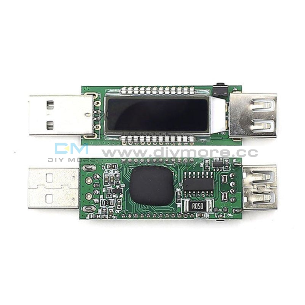
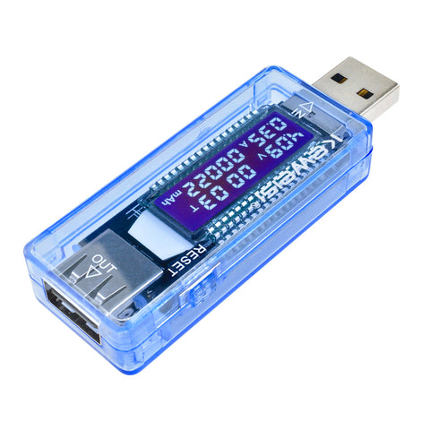 Translation missing: en.products.product.regular_price $7.99{"id":4419938418759,"title":"Arduino 2A H-Bridge Dual Channel DC Motor Driver Shield Module L298NH Than L298P","handle":"replace-l298p-for-arduino-uno-r3-dual-channel-dc-motor-driver-shield-expansion-board-l298nh-module-driving-module-mega2560-one","description":"\u003cdiv\u003e\n\u003cwidget data-widget-type=\"customText\" id=\"33684419\" title=\"Head\" type=\"custom\"\u003e\u003c\/widget\u003e \r \u003cp\u003e\u003cspan style=\"font-size: 16.0px;font-family: trebuchet ms;\"\u003e \u003c\/span\u003e\u003c\/p\u003e \r \u003cdiv\u003e \r \u003cspan style=\"font-size: 16.0px;font-family: trebuchet ms;\"\u003e \u003c\/span\u003e \r \u003cp\u003e\u003cimg src=\"https:\/\/ae01.alicdn.com\/kf\/HTB12JMgilsmBKNjSZFsq6yXSVXaS.jpg\"\u003e\u003c\/p\u003e \r \u003c\/div\u003e \r \u003cdiv\u003e \r \u003cp\u003e\u003cbr\u003e\u003c\/p\u003e \r \u003c\/div\u003e \r \u003cdiv\u003e \r \u003cspan style=\"font-size: 16.0px;font-family: trebuchet ms;\"\u003e \u003c\/span\u003e \r \u003c\/div\u003e \r \u003cdiv\u003e \r \u003cspan style=\"font-size: 16.0px;font-family: trebuchet ms;\"\u003e\u003cspan style=\"font-size: 16.0px;font-family: trebuchet ms;\"\u003eThe Motor Shield is based on the L298NH, which is a dual full-bridge driver designed to drive inductive loads such as relays, solenoids, DC and stepping motors. It lets you drive two DC motors with your for arduino board, controlling the speed and direction of each one independently. You can also measure the motor current absorption of each motor, among other features. \u003c\/span\u003e\u003c\/span\u003e \r \u003c\/div\u003e \r \u003cdiv\u003e \r \u003cspan style=\"font-size: 16.0px;font-family: trebuchet ms;\"\u003e\u003cspan style=\"font-size: 16.0px;font-family: trebuchet ms;\"\u003e•You can find in the Getting Started section all the information you need to configure your board, use the for arduino Software (IDE), and start tinker with coding and electronics. \u003c\/span\u003e\u003c\/span\u003e \r \u003c\/div\u003e \r \u003cdiv\u003e \r \u003cspan style=\"font-size: 16.0px;font-family: trebuchet ms;\"\u003e \u003c\/span\u003e \r \u003c\/div\u003e \r \u003cdiv\u003e \r \u003cspan style=\"font-size: 16.0px;font-family: trebuchet ms;color: #ff6600;\"\u003e\u003cspan style=\"font-size: 16.0px;font-family: trebuchet ms;color: #ff6600;\"\u003e\u003cstrong\u003eTechnical specs\u003c\/strong\u003e\u003c\/span\u003e\u003c\/span\u003e \r \u003c\/div\u003e \r \u003cdiv\u003e \r \u003cspan style=\"font-size: 16.0px;\"\u003e\u003cspan style=\"font-family: trebuchet ms , helvetica , sans-serif;\"\u003e\u003cspan style=\"font-size: 16.0px;font-family: trebuchet ms;\"\u003eOperating Voltage\u003c\/span\u003e\u003cspan style=\"font-size: 16.0px;font-family: trebuchet ms;\"\u003e \u003c\/span\u003e\u003cspan style=\"font-size: 16.0px;font-family: trebuchet ms;\"\u003e5V to 12V\u003c\/span\u003e\u003c\/span\u003e\u003c\/span\u003e \r \u003c\/div\u003e \r \u003cdiv\u003e \r \u003cspan style=\"font-size: 16.0px;\"\u003e\u003cspan style=\"font-family: trebuchet ms , helvetica , sans-serif;\"\u003e\u003cspan style=\"font-size: 16.0px;font-family: trebuchet ms;\"\u003eMotor controller \u003c\/span\u003e\u003cspan style=\"font-size: 16.0px;font-family: trebuchet ms;\"\u003e \u003c\/span\u003e\u003cspan style=\"font-size: 16.0px;font-family: trebuchet ms;\"\u003eL298HN, Drives 2 DC motors or 1 stepper motor\u003c\/span\u003e\u003c\/span\u003e\u003c\/span\u003e \r \u003c\/div\u003e \r \u003cdiv\u003e \r \u003cspan style=\"font-size: 16.0px;\"\u003e\u003cspan style=\"font-family: trebuchet ms , helvetica , sans-serif;\"\u003e\u003cspan style=\"font-size: 16.0px;font-family: trebuchet ms;\"\u003eMax current\u003c\/span\u003e\u003cspan style=\"font-size: 16.0px;font-family: trebuchet ms;\"\u003e \u003c\/span\u003e\u003cspan style=\"font-size: 16.0px;font-family: trebuchet ms;\"\u003e2A per channel or 4A max (with external power supply)\u003c\/span\u003e\u003c\/span\u003e\u003c\/span\u003e \r \u003c\/div\u003e \r \u003cdiv\u003e \r \u003cspan style=\"font-size: 16.0px;\"\u003e\u003cspan style=\"font-family: trebuchet ms , helvetica , sans-serif;\"\u003e\u003cspan style=\"font-size: 16.0px;font-family: trebuchet ms;\"\u003eCurrent sensing\u003c\/span\u003e\u003cspan style=\"font-size: 16.0px;font-family: trebuchet ms;\"\u003e \u003c\/span\u003e\u003cspan style=\"font-size: 16.0px;font-family: trebuchet ms;\"\u003e1.65V\/A\u003c\/span\u003e\u003c\/span\u003e\u003c\/span\u003e \r \u003c\/div\u003e \r \u003cdiv\u003e \r \u003cspan style=\"font-size: 16.0px;font-family: trebuchet ms;\"\u003e\u003cspan style=\"font-size: 16.0px;font-family: trebuchet ms;\"\u003e\u003cspan style=\"font-size: 16.0px;font-family: trebuchet ms;\"\u003eFree running stop and brake function\u003c\/span\u003e\u003c\/span\u003e\u003c\/span\u003e \r \u003c\/div\u003e \r \u003cdiv\u003e \r \u003cspan style=\"font-size: 16.0px;font-family: trebuchet ms;\"\u003e \u003c\/span\u003e \r \u003c\/div\u003e \r \u003cdiv\u003e \r \u003cspan style=\"font-size: 16.0px;font-family: trebuchet ms;color: #ff6600;\"\u003e\u003cspan style=\"font-size: 16.0px;font-family: trebuchet ms;color: #ff6600;\"\u003e\u003cstrong\u003ePower\u003c\/strong\u003e\u003c\/span\u003e\u003c\/span\u003e \r \u003c\/div\u003e \r \u003cdiv\u003e \r \u003cspan style=\"font-size: 16.0px;font-family: trebuchet ms;\"\u003e \u003c\/span\u003e \r \u003c\/div\u003e \r \u003cdiv\u003e \r \u003cspan style=\"font-size: 16.0px;font-family: trebuchet ms;\"\u003e\u003cspan style=\"font-size: 16.0px;font-family: trebuchet ms;\"\u003eThe Motor Shield must be powered only by an external power supply. Because the L298HN IC mounted on the shield has two separate power connections, one for the logic and one for the motor supply driver. The required motor current often exceeds the maximum USB current rating.\u003c\/span\u003e\u003c\/span\u003e \r \u003c\/div\u003e \r \u003cdiv\u003e \r \u003cspan style=\"font-size: 16.0px;font-family: trebuchet ms;\"\u003e\u003cspan style=\"font-size: 16.0px;font-family: trebuchet ms;\"\u003eExternal (non-USB) power can come either from an AC-to-DC adapter (wall-wart) or battery. The adapter can be connected by plugging a 2.1mm center-positive plug into the for arduino 's board power jack on which the motor shield is mounted or by connecting the wires that lead the power supply to the Vin and GND screw terminals, taking care to respect the polarities.\u003c\/span\u003e\u003c\/span\u003e \r \u003c\/div\u003e \r \u003cdiv\u003e \r \u003cspan style=\"font-size: 16.0px;font-family: trebuchet ms;\"\u003e\u003cspan style=\"font-size: 16.0px;font-family: trebuchet ms;\"\u003eTo avoid possible damage to the for arduino board on which the shield is mounted, we reccomend using an external power supply that provides a voltage between 7 and 12V. If your motor require more than 9V we recommend that you separate the power lines of the shield and the for arduino board on which the shield is mounted. This is possible by cutting the \"Vin Connect\" jumper placed on the back side of the shield. The absolute limit for the Vin at the screw terminals is 18V.\u003c\/span\u003e\u003c\/span\u003e \r \u003c\/div\u003e \r \u003cdiv\u003e \r \u003cspan style=\"font-size: 16.0px;font-family: trebuchet ms;\"\u003e\u003cspan style=\"font-size: 16.0px;font-family: trebuchet ms;\"\u003eThe shield can supply 2 amperes per channel, for a total of 4 amperes maximum. \u003c\/span\u003e\u003c\/span\u003e \r \u003c\/div\u003e \r \u003cdiv\u003e \r \u003cspan style=\"font-size: 16.0px;font-family: trebuchet ms;\"\u003e \u003c\/span\u003e \r \u003c\/div\u003e \r \u003cdiv\u003e \r \u003cspan style=\"font-size: 16.0px;font-family: trebuchet ms;color: #ff6600;\"\u003e\u003cspan style=\"font-size: 16.0px;font-family: trebuchet ms;color: #ff6600;\"\u003e\u003cstrong\u003eInput and Output\u003c\/strong\u003e\u003c\/span\u003e\u003c\/span\u003e \r \u003c\/div\u003e \r \u003cdiv\u003e \r \u003cspan style=\"font-size: 16.0px;font-family: trebuchet ms;\"\u003e \u003c\/span\u003e \r \u003c\/div\u003e \r \u003cdiv\u003e \r \u003cspan style=\"font-size: 16.0px;font-family: trebuchet ms;\"\u003e\u003cspan style=\"font-size: 16.0px;font-family: trebuchet ms;\"\u003eThis shield has two separate channels, called A and B, that each use 4 of the for arduino pins to drive or sense the motor. In total there are 8 pins in use on this shield. You can use each channel separately to drive two DC motors or combine them to drive one bipolar stepper motor. The shield's pins, divided by channel are shown in the table below: \u003c\/span\u003e\u003c\/span\u003e \r \u003c\/div\u003e \r \u003cdiv\u003e \r \u003cspan style=\"font-size: 16.0px;font-family: trebuchet ms;\"\u003e \u003c\/span\u003e \r \u003c\/div\u003e \r \u003cdiv\u003e \r \u003cspan style=\"font-size: 16.0px;\"\u003e\u003cspan style=\"font-family: trebuchet ms , helvetica , sans-serif;\"\u003e\u003cspan style=\"font-size: 16.0px;font-family: trebuchet ms;\"\u003eFunction \u003c\/span\u003e\u003cspan style=\"font-size: 16.0px;font-family: trebuchet ms;\"\u003e \u003c\/span\u003e\u003cspan style=\"font-size: 16.0px;font-family: trebuchet ms;\"\u003epins per Ch. A\u003c\/span\u003e\u003cspan style=\"font-size: 16.0px;font-family: trebuchet ms;\"\u003e \u003c\/span\u003e\u003cspan style=\"font-size: 16.0px;font-family: trebuchet ms;\"\u003epins per Ch. B\u003c\/span\u003e\u003c\/span\u003e\u003c\/span\u003e \r \u003c\/div\u003e \r \u003cdiv\u003e \r \u003cspan style=\"font-size: 16.0px;\"\u003e\u003cspan style=\"font-family: trebuchet ms , helvetica , sans-serif;\"\u003e\u003cspan style=\"font-size: 16.0px;font-family: trebuchet ms;\"\u003eDirection\u003c\/span\u003e\u003cspan style=\"font-size: 16.0px;font-family: trebuchet ms;\"\u003e \u003c\/span\u003e\u003cspan style=\"font-size: 16.0px;font-family: trebuchet ms;\"\u003eD12\u003c\/span\u003e\u003cspan style=\"font-size: 16.0px;font-family: trebuchet ms;\"\u003e \u003c\/span\u003e\u003cspan style=\"font-size: 16.0px;font-family: trebuchet ms;\"\u003eD13\u003c\/span\u003e\u003c\/span\u003e\u003c\/span\u003e \r \u003c\/div\u003e \r \u003cdiv\u003e \r \u003cspan style=\"font-size: 16.0px;\"\u003e\u003cspan style=\"font-family: trebuchet ms , helvetica , sans-serif;\"\u003e\u003cspan style=\"font-size: 16.0px;font-family: trebuchet ms;\"\u003ePWM\u003c\/span\u003e\u003cspan style=\"font-size: 16.0px;font-family: trebuchet ms;\"\u003e \u003c\/span\u003e\u003cspan style=\"font-size: 16.0px;font-family: trebuchet ms;\"\u003eD3\u003c\/span\u003e\u003cspan style=\"font-size: 16.0px;font-family: trebuchet ms;\"\u003e \u003c\/span\u003e\u003cspan style=\"font-size: 16.0px;font-family: trebuchet ms;\"\u003eD11\u003c\/span\u003e\u003c\/span\u003e\u003c\/span\u003e \r \u003c\/div\u003e \r \u003cdiv\u003e \r \u003cspan style=\"font-size: 16.0px;\"\u003e\u003cspan style=\"font-family: trebuchet ms , helvetica , sans-serif;\"\u003e\u003cspan style=\"font-size: 16.0px;font-family: trebuchet ms;\"\u003eBrake\u003c\/span\u003e\u003cspan style=\"font-size: 16.0px;font-family: trebuchet ms;\"\u003e \u003c\/span\u003e\u003cspan style=\"font-size: 16.0px;font-family: trebuchet ms;\"\u003eD9\u003c\/span\u003e\u003cspan style=\"font-size: 16.0px;font-family: trebuchet ms;\"\u003e \u003c\/span\u003e\u003cspan style=\"font-size: 16.0px;font-family: trebuchet ms;\"\u003eD8\u003c\/span\u003e\u003c\/span\u003e\u003c\/span\u003e \r \u003c\/div\u003e \r \u003cdiv\u003e \r \u003cspan style=\"font-size: 16.0px;\"\u003e\u003cspan style=\"font-family: trebuchet ms , helvetica , sans-serif;\"\u003e\u003cspan style=\"font-size: 16.0px;font-family: trebuchet ms;\"\u003eCurrent Sensing\u003c\/span\u003e\u003cspan style=\"font-size: 16.0px;font-family: trebuchet ms;\"\u003e \u003c\/span\u003e\u003cspan style=\"font-size: 16.0px;font-family: trebuchet ms;\"\u003eA0 \u003c\/span\u003e\u003cspan style=\"font-size: 16.0px;font-family: trebuchet ms;\"\u003e \u003c\/span\u003e\u003cspan style=\"font-size: 16.0px;font-family: trebuchet ms;\"\u003eA1\u003c\/span\u003e\u003c\/span\u003e\u003c\/span\u003e \r \u003c\/div\u003e \r \u003cdiv\u003e \r \u003cspan style=\"font-size: 16.0px;font-family: trebuchet ms;\"\u003e \u003c\/span\u003e \r \u003c\/div\u003e \r \u003cdiv\u003e \r \u003cspan style=\"font-size: 16.0px;font-family: trebuchet ms;\"\u003e\u003cspan style=\"font-size: 16.0px;font-family: trebuchet ms;\"\u003eIf you don't need the Brake and the Current Sensing and you also need more pins for your application you can disable this features by cutting the respective jumpers on the back side of the shield. \u003c\/span\u003e\u003c\/span\u003e \r \u003c\/div\u003e \r \u003cdiv\u003e \r \u003cspan style=\"font-size: 16.0px;font-family: trebuchet ms;\"\u003e \u003c\/span\u003e \r \u003c\/div\u003e \r \u003cdiv\u003e \r \u003cspan style=\"font-size: 16.0px;font-family: trebuchet ms;color: #ff6600;\"\u003e\u003cspan style=\"font-size: 16.0px;font-family: trebuchet ms;color: #ff6600;\"\u003e\u003cstrong\u003eMotors Connection\u003c\/strong\u003e\u003c\/span\u003e\u003c\/span\u003e \r \u003c\/div\u003e \r \u003cdiv\u003e \r \u003cspan style=\"font-size: 16.0px;font-family: trebuchet ms;\"\u003e\u003cspan style=\"font-size: 16.0px;font-family: trebuchet ms;\"\u003eBrushed DC motor. You can drive two Brushed DC motors by connecting the two wires of each one in the (+) and (-) screw terminals for each channel A and B. In this way you can control its direction by setting HIGH or LOW the DIR A and DIR B pins, you can control the speed by varying the PWM A and PWM B duty cycle values. The Brake A and Brake B pins, if set HIGH, will effectively brake the DC motors rather than let them slow down by cutting the power. You can measure the current going through the DC motor by reading the SNS0 and SNS1 pins. On each channel will be a voltage proportional to the measured current, which can be read as a normal analog input, through the function analogRead() on the analog input A0 and A1. For your convenience it is calibrated to be 3.3V when the channel is delivering its maximum possible current, that is 2A. \u003c\/span\u003e\u003c\/span\u003e \r \u003c\/div\u003e \r \u003cdiv\u003e \r \u003cspan style=\"font-size: 16.0px;font-family: trebuchet ms;\"\u003e \u003c\/span\u003e \r \u003c\/div\u003e \r \u003cdiv\u003e \r \u003cspan style=\"font-size: 16.0px;font-family: trebuchet ms;\"\u003e \u003c\/span\u003e \r \u003c\/div\u003e \r \u003cdiv\u003e \r \u003cspan style=\"font-size: 16.0px;font-family: trebuchet ms;\"\u003e \u003c\/span\u003e \r \u003c\/div\u003e \r \u003cdiv\u003e \r \u003cspan style=\"font-size: 16.0px;font-family: trebuchet ms;\"\u003e \u003c\/span\u003e \r \u003c\/div\u003e \r \u003cdiv\u003e \r \u003cspan style=\"font-size: 16.0px;font-family: trebuchet ms;color: #ff6600;\"\u003e\u003cstrong\u003e \u003c\/strong\u003e\u003c\/span\u003e \r \u003cspan style=\"font-size: 16.0px;font-family: trebuchet ms;color: #ff6600;\"\u003e\u003cspan style=\"font-size: 16.0px;font-family: trebuchet ms;color: #ff6600;\"\u003e\u003cstrong\u003ePackage Included:\u003c\/strong\u003e\u003c\/span\u003e\u003c\/span\u003e \r \u003c\/div\u003e \r \u003cdiv\u003e \r \u003cspan style=\"font-size: 16.0px;font-family: trebuchet ms;\"\u003e \u003c\/span\u003e \r \u003c\/div\u003e \r \u003cdiv\u003e \r \u003cspan style=\"font-size: 16.0px;font-family: trebuchet ms;\"\u003e 1 x L298NH Dual Channel DC Motor Driver Shield Board\u003c\/span\u003e \r \u003c\/div\u003e \r \u003cp\u003e\u003cspan style=\"font-size: 16.0px;font-family: trebuchet ms;\"\u003e \u003c\/span\u003e\u003c\/p\u003e \r \u003cp\u003e\u003cspan style=\"font-size: 16.0px;font-family: trebuchet ms;\"\u003e \u003c\/span\u003e\u003c\/p\u003e \r \u003cspan style=\"font-size: 16.0px;font-family: trebuchet ms;\"\u003e \u003cp\u003e\u003cimg src=\"https:\/\/ae01.alicdn.com\/kf\/HTB1VXjubuUXBuNjt_a0q6AysXXaA.jpg\"\u003e\u003c\/p\u003e\n\u003cp\u003e \u003c\/p\u003e\n\u003cp\u003e\u003cimg style=\"width: 1000.0px;\" src=\"https:\/\/ae01.alicdn.com\/kf\/HTB1acVFa6vuK1Rjy0Faq6x2aVXaR.jpg\"\u003e\u003c\/p\u003e\n\u003cp\u003e\u003cimg style=\"width: 1000.0px;\" src=\"https:\/\/ae01.alicdn.com\/kf\/HTB14yJHa.rrK1RkSne1q6ArVVXaJ.jpg\"\u003e\u003c\/p\u003e\n\u003cp\u003e\u003cbr\u003e\u003c\/p\u003e\n\u003cp\u003e\u003cimg style=\"width: 1000.0px;\" src=\"https:\/\/ae01.alicdn.com\/kf\/HTB1VvpAa.vrK1RjSszfq6xJNVXat.jpg\"\u003e\u003c\/p\u003e\n\u003cp\u003e\u003cimg style=\"width: 1000.0px;\" src=\"https:\/\/ae01.alicdn.com\/kf\/HTB1yj5TaPLuK1Rjy0Fhq6xpdFXa6.jpg\"\u003e\u003c\/p\u003e\n\u003cp\u003e\u003cimg style=\"width: 1000.0px;\" src=\"https:\/\/ae01.alicdn.com\/kf\/HTB1WhJCa5DxK1Rjy1zcq6yGeXXai.jpg\"\u003e\u003c\/p\u003e\n\u003cp\u003e \u003c\/p\u003e\n\u003cp\u003e\u003cimg src=\"https:\/\/ae01.alicdn.com\/kf\/HTB1Hc.uimcqBKNjSZFgq6x_kXXaq.jpg\"\u003e\u003c\/p\u003e\n\u003cp\u003e \u003c\/p\u003e\n\u003cp\u003e \r \u003cwidget data-widget-type=\"customText\" id=\"24006699\" title=\"Related\" type=\"custom\"\u003e\u003c\/widget\u003e \u003c\/p\u003e\u003c\/span\u003e \r \u003cp\u003e\u003c\/p\u003e \r \u003cp\u003e\u003cspan style=\"font-size: 16.0px;font-family: trebuchet ms;\"\u003e \u003c\/span\u003e\u003c\/p\u003e \u003cscript\u003ewindow.adminAccountId=227552571;\u003c\/script\u003e \u003c\/div\u003e","published_at":"2019-12-27T16:28:18+08:00","created_at":"2019-12-27T16:28:30+08:00","vendor":"diymore","type":"Integrated Circuits","tags":[],"price":899,"price_min":899,"price_max":899,"available":true,"price_varies":false,"compare_at_price":null,"compare_at_price_min":0,"compare_at_price_max":0,"compare_at_price_varies":false,"variants":[{"id":31582607409223,"title":"Default Title","option1":"Default Title","option2":null,"option3":null,"sku":"180030","requires_shipping":true,"taxable":true,"featured_image":null,"available":true,"name":"Arduino 2A H-Bridge Dual Channel DC Motor Driver Shield Module L298NH Than L298P","public_title":null,"options":["Default Title"],"price":899,"weight":30,"compare_at_price":null,"inventory_management":null,"barcode":"","requires_selling_plan":false,"selling_plan_allocations":[],"quantity_rule":{"min":1,"max":null,"increment":1}}],"images":["\/\/www.diymore.cc\/cdn\/shop\/products\/Replace-L298P-For-Arduino-UNO-R3-Dual-Channel-DC-Motor-Driver-Shield-Expansion-Board-L298NH-Module_259.jpg?v=1588697940","\/\/www.diymore.cc\/cdn\/shop\/products\/Replace-L298P-For-Arduino-UNO-R3-Dual-Channel-DC-Motor-Driver-Shield-Expansion-Board-L298NH-Module_63b77384-930b-4e89-8b62-17bdb7ff23c5_644.jpg?v=1588697940","\/\/www.diymore.cc\/cdn\/shop\/products\/Replace-L298P-For-Arduino-UNO-R3-Dual-Channel-DC-Motor-Driver-Shield-Expansion-Board-L298NH-Module_0a80a83c-dc2f-460c-a034-768bd412d88c_731.jpg?v=1588697940","\/\/www.diymore.cc\/cdn\/shop\/products\/Replace-L298P-For-Arduino-UNO-R3-Dual-Channel-DC-Motor-Driver-Shield-Expansion-Board-L298NH-Module_10e0ead5-7c58-4cd0-9dbc-9e26210641df_203.jpg?v=1588697940","\/\/www.diymore.cc\/cdn\/shop\/products\/Replace-L298P-For-Arduino-UNO-R3-Dual-Channel-DC-Motor-Driver-Shield-Expansion-Board-L298NH-Module_c95cb3f4-de34-4a9e-b289-07a336bce0ef_828.jpg?v=1588697940"],"featured_image":"\/\/www.diymore.cc\/cdn\/shop\/products\/Replace-L298P-For-Arduino-UNO-R3-Dual-Channel-DC-Motor-Driver-Shield-Expansion-Board-L298NH-Module_259.jpg?v=1588697940","options":["Title"],"media":[{"alt":"Replace L298P For Arduino Uno R3 Dual Channel Dc Motor Driver Shield Expansion Board L298Nh Module","id":6682319224903,"position":1,"preview_image":{"aspect_ratio":1.0,"height":1000,"width":1000,"src":"\/\/www.diymore.cc\/cdn\/shop\/products\/Replace-L298P-For-Arduino-UNO-R3-Dual-Channel-DC-Motor-Driver-Shield-Expansion-Board-L298NH-Module_259.jpg?v=1588697940"},"aspect_ratio":1.0,"height":1000,"media_type":"image","src":"\/\/www.diymore.cc\/cdn\/shop\/products\/Replace-L298P-For-Arduino-UNO-R3-Dual-Channel-DC-Motor-Driver-Shield-Expansion-Board-L298NH-Module_259.jpg?v=1588697940","width":1000},{"alt":"Replace L298P For Arduino Uno R3 Dual Channel Dc Motor Driver Shield Expansion Board L298Nh Module","id":6682319355975,"position":2,"preview_image":{"aspect_ratio":1.0,"height":1000,"width":1000,"src":"\/\/www.diymore.cc\/cdn\/shop\/products\/Replace-L298P-For-Arduino-UNO-R3-Dual-Channel-DC-Motor-Driver-Shield-Expansion-Board-L298NH-Module_63b77384-930b-4e89-8b62-17bdb7ff23c5_644.jpg?v=1588697940"},"aspect_ratio":1.0,"height":1000,"media_type":"image","src":"\/\/www.diymore.cc\/cdn\/shop\/products\/Replace-L298P-For-Arduino-UNO-R3-Dual-Channel-DC-Motor-Driver-Shield-Expansion-Board-L298NH-Module_63b77384-930b-4e89-8b62-17bdb7ff23c5_644.jpg?v=1588697940","width":1000},{"alt":"Replace L298P For Arduino Uno R3 Dual Channel Dc Motor Driver Shield Expansion Board L298Nh Module","id":6682319585351,"position":3,"preview_image":{"aspect_ratio":1.0,"height":1000,"width":1000,"src":"\/\/www.diymore.cc\/cdn\/shop\/products\/Replace-L298P-For-Arduino-UNO-R3-Dual-Channel-DC-Motor-Driver-Shield-Expansion-Board-L298NH-Module_0a80a83c-dc2f-460c-a034-768bd412d88c_731.jpg?v=1588697940"},"aspect_ratio":1.0,"height":1000,"media_type":"image","src":"\/\/www.diymore.cc\/cdn\/shop\/products\/Replace-L298P-For-Arduino-UNO-R3-Dual-Channel-DC-Motor-Driver-Shield-Expansion-Board-L298NH-Module_0a80a83c-dc2f-460c-a034-768bd412d88c_731.jpg?v=1588697940","width":1000},{"alt":"Replace L298P For Arduino Uno R3 Dual Channel Dc Motor Driver Shield Expansion Board L298Nh Module","id":6682319716423,"position":4,"preview_image":{"aspect_ratio":1.0,"height":1000,"width":1000,"src":"\/\/www.diymore.cc\/cdn\/shop\/products\/Replace-L298P-For-Arduino-UNO-R3-Dual-Channel-DC-Motor-Driver-Shield-Expansion-Board-L298NH-Module_10e0ead5-7c58-4cd0-9dbc-9e26210641df_203.jpg?v=1588697940"},"aspect_ratio":1.0,"height":1000,"media_type":"image","src":"\/\/www.diymore.cc\/cdn\/shop\/products\/Replace-L298P-For-Arduino-UNO-R3-Dual-Channel-DC-Motor-Driver-Shield-Expansion-Board-L298NH-Module_10e0ead5-7c58-4cd0-9dbc-9e26210641df_203.jpg?v=1588697940","width":1000},{"alt":"Replace L298P For Arduino Uno R3 Dual Channel Dc Motor Driver Shield Expansion Board L298Nh Module","id":6682319781959,"position":5,"preview_image":{"aspect_ratio":1.0,"height":1000,"width":1000,"src":"\/\/www.diymore.cc\/cdn\/shop\/products\/Replace-L298P-For-Arduino-UNO-R3-Dual-Channel-DC-Motor-Driver-Shield-Expansion-Board-L298NH-Module_c95cb3f4-de34-4a9e-b289-07a336bce0ef_828.jpg?v=1588697940"},"aspect_ratio":1.0,"height":1000,"media_type":"image","src":"\/\/www.diymore.cc\/cdn\/shop\/products\/Replace-L298P-For-Arduino-UNO-R3-Dual-Channel-DC-Motor-Driver-Shield-Expansion-Board-L298NH-Module_c95cb3f4-de34-4a9e-b289-07a336bce0ef_828.jpg?v=1588697940","width":1000}],"requires_selling_plan":false,"selling_plan_groups":[],"content":"\u003cdiv\u003e\n\u003cwidget data-widget-type=\"customText\" id=\"33684419\" title=\"Head\" type=\"custom\"\u003e\u003c\/widget\u003e \r \u003cp\u003e\u003cspan style=\"font-size: 16.0px;font-family: trebuchet ms;\"\u003e \u003c\/span\u003e\u003c\/p\u003e \r \u003cdiv\u003e \r \u003cspan style=\"font-size: 16.0px;font-family: trebuchet ms;\"\u003e \u003c\/span\u003e \r \u003cp\u003e\u003cimg src=\"https:\/\/ae01.alicdn.com\/kf\/HTB12JMgilsmBKNjSZFsq6yXSVXaS.jpg\"\u003e\u003c\/p\u003e \r \u003c\/div\u003e \r \u003cdiv\u003e \r \u003cp\u003e\u003cbr\u003e\u003c\/p\u003e \r \u003c\/div\u003e \r \u003cdiv\u003e \r \u003cspan style=\"font-size: 16.0px;font-family: trebuchet ms;\"\u003e \u003c\/span\u003e \r \u003c\/div\u003e \r \u003cdiv\u003e \r \u003cspan style=\"font-size: 16.0px;font-family: trebuchet ms;\"\u003e\u003cspan style=\"font-size: 16.0px;font-family: trebuchet ms;\"\u003eThe Motor Shield is based on the L298NH, which is a dual full-bridge driver designed to drive inductive loads such as relays, solenoids, DC and stepping motors. It lets you drive two DC motors with your for arduino board, controlling the speed and direction of each one independently. You can also measure the motor current absorption of each motor, among other features. \u003c\/span\u003e\u003c\/span\u003e \r \u003c\/div\u003e \r \u003cdiv\u003e \r \u003cspan style=\"font-size: 16.0px;font-family: trebuchet ms;\"\u003e\u003cspan style=\"font-size: 16.0px;font-family: trebuchet ms;\"\u003e•You can find in the Getting Started section all the information you need to configure your board, use the for arduino Software (IDE), and start tinker with coding and electronics. \u003c\/span\u003e\u003c\/span\u003e \r \u003c\/div\u003e \r \u003cdiv\u003e \r \u003cspan style=\"font-size: 16.0px;font-family: trebuchet ms;\"\u003e \u003c\/span\u003e \r \u003c\/div\u003e \r \u003cdiv\u003e \r \u003cspan style=\"font-size: 16.0px;font-family: trebuchet ms;color: #ff6600;\"\u003e\u003cspan style=\"font-size: 16.0px;font-family: trebuchet ms;color: #ff6600;\"\u003e\u003cstrong\u003eTechnical specs\u003c\/strong\u003e\u003c\/span\u003e\u003c\/span\u003e \r \u003c\/div\u003e \r \u003cdiv\u003e \r \u003cspan style=\"font-size: 16.0px;\"\u003e\u003cspan style=\"font-family: trebuchet ms , helvetica , sans-serif;\"\u003e\u003cspan style=\"font-size: 16.0px;font-family: trebuchet ms;\"\u003eOperating Voltage\u003c\/span\u003e\u003cspan style=\"font-size: 16.0px;font-family: trebuchet ms;\"\u003e \u003c\/span\u003e\u003cspan style=\"font-size: 16.0px;font-family: trebuchet ms;\"\u003e5V to 12V\u003c\/span\u003e\u003c\/span\u003e\u003c\/span\u003e \r \u003c\/div\u003e \r \u003cdiv\u003e \r \u003cspan style=\"font-size: 16.0px;\"\u003e\u003cspan style=\"font-family: trebuchet ms , helvetica , sans-serif;\"\u003e\u003cspan style=\"font-size: 16.0px;font-family: trebuchet ms;\"\u003eMotor controller \u003c\/span\u003e\u003cspan style=\"font-size: 16.0px;font-family: trebuchet ms;\"\u003e \u003c\/span\u003e\u003cspan style=\"font-size: 16.0px;font-family: trebuchet ms;\"\u003eL298HN, Drives 2 DC motors or 1 stepper motor\u003c\/span\u003e\u003c\/span\u003e\u003c\/span\u003e \r \u003c\/div\u003e \r \u003cdiv\u003e \r \u003cspan style=\"font-size: 16.0px;\"\u003e\u003cspan style=\"font-family: trebuchet ms , helvetica , sans-serif;\"\u003e\u003cspan style=\"font-size: 16.0px;font-family: trebuchet ms;\"\u003eMax current\u003c\/span\u003e\u003cspan style=\"font-size: 16.0px;font-family: trebuchet ms;\"\u003e \u003c\/span\u003e\u003cspan style=\"font-size: 16.0px;font-family: trebuchet ms;\"\u003e2A per channel or 4A max (with external power supply)\u003c\/span\u003e\u003c\/span\u003e\u003c\/span\u003e \r \u003c\/div\u003e \r \u003cdiv\u003e \r \u003cspan style=\"font-size: 16.0px;\"\u003e\u003cspan style=\"font-family: trebuchet ms , helvetica , sans-serif;\"\u003e\u003cspan style=\"font-size: 16.0px;font-family: trebuchet ms;\"\u003eCurrent sensing\u003c\/span\u003e\u003cspan style=\"font-size: 16.0px;font-family: trebuchet ms;\"\u003e \u003c\/span\u003e\u003cspan style=\"font-size: 16.0px;font-family: trebuchet ms;\"\u003e1.65V\/A\u003c\/span\u003e\u003c\/span\u003e\u003c\/span\u003e \r \u003c\/div\u003e \r \u003cdiv\u003e \r \u003cspan style=\"font-size: 16.0px;font-family: trebuchet ms;\"\u003e\u003cspan style=\"font-size: 16.0px;font-family: trebuchet ms;\"\u003e\u003cspan style=\"font-size: 16.0px;font-family: trebuchet ms;\"\u003eFree running stop and brake function\u003c\/span\u003e\u003c\/span\u003e\u003c\/span\u003e \r \u003c\/div\u003e \r \u003cdiv\u003e \r \u003cspan style=\"font-size: 16.0px;font-family: trebuchet ms;\"\u003e \u003c\/span\u003e \r \u003c\/div\u003e \r \u003cdiv\u003e \r \u003cspan style=\"font-size: 16.0px;font-family: trebuchet ms;color: #ff6600;\"\u003e\u003cspan style=\"font-size: 16.0px;font-family: trebuchet ms;color: #ff6600;\"\u003e\u003cstrong\u003ePower\u003c\/strong\u003e\u003c\/span\u003e\u003c\/span\u003e \r \u003c\/div\u003e \r \u003cdiv\u003e \r \u003cspan style=\"font-size: 16.0px;font-family: trebuchet ms;\"\u003e \u003c\/span\u003e \r \u003c\/div\u003e \r \u003cdiv\u003e \r \u003cspan style=\"font-size: 16.0px;font-family: trebuchet ms;\"\u003e\u003cspan style=\"font-size: 16.0px;font-family: trebuchet ms;\"\u003eThe Motor Shield must be powered only by an external power supply. Because the L298HN IC mounted on the shield has two separate power connections, one for the logic and one for the motor supply driver. The required motor current often exceeds the maximum USB current rating.\u003c\/span\u003e\u003c\/span\u003e \r \u003c\/div\u003e \r \u003cdiv\u003e \r \u003cspan style=\"font-size: 16.0px;font-family: trebuchet ms;\"\u003e\u003cspan style=\"font-size: 16.0px;font-family: trebuchet ms;\"\u003eExternal (non-USB) power can come either from an AC-to-DC adapter (wall-wart) or battery. The adapter can be connected by plugging a 2.1mm center-positive plug into the for arduino 's board power jack on which the motor shield is mounted or by connecting the wires that lead the power supply to the Vin and GND screw terminals, taking care to respect the polarities.\u003c\/span\u003e\u003c\/span\u003e \r \u003c\/div\u003e \r \u003cdiv\u003e \r \u003cspan style=\"font-size: 16.0px;font-family: trebuchet ms;\"\u003e\u003cspan style=\"font-size: 16.0px;font-family: trebuchet ms;\"\u003eTo avoid possible damage to the for arduino board on which the shield is mounted, we reccomend using an external power supply that provides a voltage between 7 and 12V. If your motor require more than 9V we recommend that you separate the power lines of the shield and the for arduino board on which the shield is mounted. This is possible by cutting the \"Vin Connect\" jumper placed on the back side of the shield. The absolute limit for the Vin at the screw terminals is 18V.\u003c\/span\u003e\u003c\/span\u003e \r \u003c\/div\u003e \r \u003cdiv\u003e \r \u003cspan style=\"font-size: 16.0px;font-family: trebuchet ms;\"\u003e\u003cspan style=\"font-size: 16.0px;font-family: trebuchet ms;\"\u003eThe shield can supply 2 amperes per channel, for a total of 4 amperes maximum. \u003c\/span\u003e\u003c\/span\u003e \r \u003c\/div\u003e \r \u003cdiv\u003e \r \u003cspan style=\"font-size: 16.0px;font-family: trebuchet ms;\"\u003e \u003c\/span\u003e \r \u003c\/div\u003e \r \u003cdiv\u003e \r \u003cspan style=\"font-size: 16.0px;font-family: trebuchet ms;color: #ff6600;\"\u003e\u003cspan style=\"font-size: 16.0px;font-family: trebuchet ms;color: #ff6600;\"\u003e\u003cstrong\u003eInput and Output\u003c\/strong\u003e\u003c\/span\u003e\u003c\/span\u003e \r \u003c\/div\u003e \r \u003cdiv\u003e \r \u003cspan style=\"font-size: 16.0px;font-family: trebuchet ms;\"\u003e \u003c\/span\u003e \r \u003c\/div\u003e \r \u003cdiv\u003e \r \u003cspan style=\"font-size: 16.0px;font-family: trebuchet ms;\"\u003e\u003cspan style=\"font-size: 16.0px;font-family: trebuchet ms;\"\u003eThis shield has two separate channels, called A and B, that each use 4 of the for arduino pins to drive or sense the motor. In total there are 8 pins in use on this shield. You can use each channel separately to drive two DC motors or combine them to drive one bipolar stepper motor. The shield's pins, divided by channel are shown in the table below: \u003c\/span\u003e\u003c\/span\u003e \r \u003c\/div\u003e \r \u003cdiv\u003e \r \u003cspan style=\"font-size: 16.0px;font-family: trebuchet ms;\"\u003e \u003c\/span\u003e \r \u003c\/div\u003e \r \u003cdiv\u003e \r \u003cspan style=\"font-size: 16.0px;\"\u003e\u003cspan style=\"font-family: trebuchet ms , helvetica , sans-serif;\"\u003e\u003cspan style=\"font-size: 16.0px;font-family: trebuchet ms;\"\u003eFunction \u003c\/span\u003e\u003cspan style=\"font-size: 16.0px;font-family: trebuchet ms;\"\u003e \u003c\/span\u003e\u003cspan style=\"font-size: 16.0px;font-family: trebuchet ms;\"\u003epins per Ch. A\u003c\/span\u003e\u003cspan style=\"font-size: 16.0px;font-family: trebuchet ms;\"\u003e \u003c\/span\u003e\u003cspan style=\"font-size: 16.0px;font-family: trebuchet ms;\"\u003epins per Ch. B\u003c\/span\u003e\u003c\/span\u003e\u003c\/span\u003e \r \u003c\/div\u003e \r \u003cdiv\u003e \r \u003cspan style=\"font-size: 16.0px;\"\u003e\u003cspan style=\"font-family: trebuchet ms , helvetica , sans-serif;\"\u003e\u003cspan style=\"font-size: 16.0px;font-family: trebuchet ms;\"\u003eDirection\u003c\/span\u003e\u003cspan style=\"font-size: 16.0px;font-family: trebuchet ms;\"\u003e \u003c\/span\u003e\u003cspan style=\"font-size: 16.0px;font-family: trebuchet ms;\"\u003eD12\u003c\/span\u003e\u003cspan style=\"font-size: 16.0px;font-family: trebuchet ms;\"\u003e \u003c\/span\u003e\u003cspan style=\"font-size: 16.0px;font-family: trebuchet ms;\"\u003eD13\u003c\/span\u003e\u003c\/span\u003e\u003c\/span\u003e \r \u003c\/div\u003e \r \u003cdiv\u003e \r \u003cspan style=\"font-size: 16.0px;\"\u003e\u003cspan style=\"font-family: trebuchet ms , helvetica , sans-serif;\"\u003e\u003cspan style=\"font-size: 16.0px;font-family: trebuchet ms;\"\u003ePWM\u003c\/span\u003e\u003cspan style=\"font-size: 16.0px;font-family: trebuchet ms;\"\u003e \u003c\/span\u003e\u003cspan style=\"font-size: 16.0px;font-family: trebuchet ms;\"\u003eD3\u003c\/span\u003e\u003cspan style=\"font-size: 16.0px;font-family: trebuchet ms;\"\u003e \u003c\/span\u003e\u003cspan style=\"font-size: 16.0px;font-family: trebuchet ms;\"\u003eD11\u003c\/span\u003e\u003c\/span\u003e\u003c\/span\u003e \r \u003c\/div\u003e \r \u003cdiv\u003e \r \u003cspan style=\"font-size: 16.0px;\"\u003e\u003cspan style=\"font-family: trebuchet ms , helvetica , sans-serif;\"\u003e\u003cspan style=\"font-size: 16.0px;font-family: trebuchet ms;\"\u003eBrake\u003c\/span\u003e\u003cspan style=\"font-size: 16.0px;font-family: trebuchet ms;\"\u003e \u003c\/span\u003e\u003cspan style=\"font-size: 16.0px;font-family: trebuchet ms;\"\u003eD9\u003c\/span\u003e\u003cspan style=\"font-size: 16.0px;font-family: trebuchet ms;\"\u003e \u003c\/span\u003e\u003cspan style=\"font-size: 16.0px;font-family: trebuchet ms;\"\u003eD8\u003c\/span\u003e\u003c\/span\u003e\u003c\/span\u003e \r \u003c\/div\u003e \r \u003cdiv\u003e \r \u003cspan style=\"font-size: 16.0px;\"\u003e\u003cspan style=\"font-family: trebuchet ms , helvetica , sans-serif;\"\u003e\u003cspan style=\"font-size: 16.0px;font-family: trebuchet ms;\"\u003eCurrent Sensing\u003c\/span\u003e\u003cspan style=\"font-size: 16.0px;font-family: trebuchet ms;\"\u003e \u003c\/span\u003e\u003cspan style=\"font-size: 16.0px;font-family: trebuchet ms;\"\u003eA0 \u003c\/span\u003e\u003cspan style=\"font-size: 16.0px;font-family: trebuchet ms;\"\u003e \u003c\/span\u003e\u003cspan style=\"font-size: 16.0px;font-family: trebuchet ms;\"\u003eA1\u003c\/span\u003e\u003c\/span\u003e\u003c\/span\u003e \r \u003c\/div\u003e \r \u003cdiv\u003e \r \u003cspan style=\"font-size: 16.0px;font-family: trebuchet ms;\"\u003e \u003c\/span\u003e \r \u003c\/div\u003e \r \u003cdiv\u003e \r \u003cspan style=\"font-size: 16.0px;font-family: trebuchet ms;\"\u003e\u003cspan style=\"font-size: 16.0px;font-family: trebuchet ms;\"\u003eIf you don't need the Brake and the Current Sensing and you also need more pins for your application you can disable this features by cutting the respective jumpers on the back side of the shield. \u003c\/span\u003e\u003c\/span\u003e \r \u003c\/div\u003e \r \u003cdiv\u003e \r \u003cspan style=\"font-size: 16.0px;font-family: trebuchet ms;\"\u003e \u003c\/span\u003e \r \u003c\/div\u003e \r \u003cdiv\u003e \r \u003cspan style=\"font-size: 16.0px;font-family: trebuchet ms;color: #ff6600;\"\u003e\u003cspan style=\"font-size: 16.0px;font-family: trebuchet ms;color: #ff6600;\"\u003e\u003cstrong\u003eMotors Connection\u003c\/strong\u003e\u003c\/span\u003e\u003c\/span\u003e \r \u003c\/div\u003e \r \u003cdiv\u003e \r \u003cspan style=\"font-size: 16.0px;font-family: trebuchet ms;\"\u003e\u003cspan style=\"font-size: 16.0px;font-family: trebuchet ms;\"\u003eBrushed DC motor. You can drive two Brushed DC motors by connecting the two wires of each one in the (+) and (-) screw terminals for each channel A and B. In this way you can control its direction by setting HIGH or LOW the DIR A and DIR B pins, you can control the speed by varying the PWM A and PWM B duty cycle values. The Brake A and Brake B pins, if set HIGH, will effectively brake the DC motors rather than let them slow down by cutting the power. You can measure the current going through the DC motor by reading the SNS0 and SNS1 pins. On each channel will be a voltage proportional to the measured current, which can be read as a normal analog input, through the function analogRead() on the analog input A0 and A1. For your convenience it is calibrated to be 3.3V when the channel is delivering its maximum possible current, that is 2A. \u003c\/span\u003e\u003c\/span\u003e \r \u003c\/div\u003e \r \u003cdiv\u003e \r \u003cspan style=\"font-size: 16.0px;font-family: trebuchet ms;\"\u003e \u003c\/span\u003e \r \u003c\/div\u003e \r \u003cdiv\u003e \r \u003cspan style=\"font-size: 16.0px;font-family: trebuchet ms;\"\u003e \u003c\/span\u003e \r \u003c\/div\u003e \r \u003cdiv\u003e \r \u003cspan style=\"font-size: 16.0px;font-family: trebuchet ms;\"\u003e \u003c\/span\u003e \r \u003c\/div\u003e \r \u003cdiv\u003e \r \u003cspan style=\"font-size: 16.0px;font-family: trebuchet ms;\"\u003e \u003c\/span\u003e \r \u003c\/div\u003e \r \u003cdiv\u003e \r \u003cspan style=\"font-size: 16.0px;font-family: trebuchet ms;color: #ff6600;\"\u003e\u003cstrong\u003e \u003c\/strong\u003e\u003c\/span\u003e \r \u003cspan style=\"font-size: 16.0px;font-family: trebuchet ms;color: #ff6600;\"\u003e\u003cspan style=\"font-size: 16.0px;font-family: trebuchet ms;color: #ff6600;\"\u003e\u003cstrong\u003ePackage Included:\u003c\/strong\u003e\u003c\/span\u003e\u003c\/span\u003e \r \u003c\/div\u003e \r \u003cdiv\u003e \r \u003cspan style=\"font-size: 16.0px;font-family: trebuchet ms;\"\u003e \u003c\/span\u003e \r \u003c\/div\u003e \r \u003cdiv\u003e \r \u003cspan style=\"font-size: 16.0px;font-family: trebuchet ms;\"\u003e 1 x L298NH Dual Channel DC Motor Driver Shield Board\u003c\/span\u003e \r \u003c\/div\u003e \r \u003cp\u003e\u003cspan style=\"font-size: 16.0px;font-family: trebuchet ms;\"\u003e \u003c\/span\u003e\u003c\/p\u003e \r \u003cp\u003e\u003cspan style=\"font-size: 16.0px;font-family: trebuchet ms;\"\u003e \u003c\/span\u003e\u003c\/p\u003e \r \u003cspan style=\"font-size: 16.0px;font-family: trebuchet ms;\"\u003e \u003cp\u003e\u003cimg src=\"https:\/\/ae01.alicdn.com\/kf\/HTB1VXjubuUXBuNjt_a0q6AysXXaA.jpg\"\u003e\u003c\/p\u003e\n\u003cp\u003e \u003c\/p\u003e\n\u003cp\u003e\u003cimg style=\"width: 1000.0px;\" src=\"https:\/\/ae01.alicdn.com\/kf\/HTB1acVFa6vuK1Rjy0Faq6x2aVXaR.jpg\"\u003e\u003c\/p\u003e\n\u003cp\u003e\u003cimg style=\"width: 1000.0px;\" src=\"https:\/\/ae01.alicdn.com\/kf\/HTB14yJHa.rrK1RkSne1q6ArVVXaJ.jpg\"\u003e\u003c\/p\u003e\n\u003cp\u003e\u003cbr\u003e\u003c\/p\u003e\n\u003cp\u003e\u003cimg style=\"width: 1000.0px;\" src=\"https:\/\/ae01.alicdn.com\/kf\/HTB1VvpAa.vrK1RjSszfq6xJNVXat.jpg\"\u003e\u003c\/p\u003e\n\u003cp\u003e\u003cimg style=\"width: 1000.0px;\" src=\"https:\/\/ae01.alicdn.com\/kf\/HTB1yj5TaPLuK1Rjy0Fhq6xpdFXa6.jpg\"\u003e\u003c\/p\u003e\n\u003cp\u003e\u003cimg style=\"width: 1000.0px;\" src=\"https:\/\/ae01.alicdn.com\/kf\/HTB1WhJCa5DxK1Rjy1zcq6yGeXXai.jpg\"\u003e\u003c\/p\u003e\n\u003cp\u003e \u003c\/p\u003e\n\u003cp\u003e\u003cimg src=\"https:\/\/ae01.alicdn.com\/kf\/HTB1Hc.uimcqBKNjSZFgq6x_kXXaq.jpg\"\u003e\u003c\/p\u003e\n\u003cp\u003e \u003c\/p\u003e\n\u003cp\u003e \r \u003cwidget data-widget-type=\"customText\" id=\"24006699\" title=\"Related\" type=\"custom\"\u003e\u003c\/widget\u003e \u003c\/p\u003e\u003c\/span\u003e \r \u003cp\u003e\u003c\/p\u003e \r \u003cp\u003e\u003cspan style=\"font-size: 16.0px;font-family: trebuchet ms;\"\u003e \u003c\/span\u003e\u003c\/p\u003e \u003cscript\u003ewindow.adminAccountId=227552571;\u003c\/script\u003e \u003c\/div\u003e"}
 -
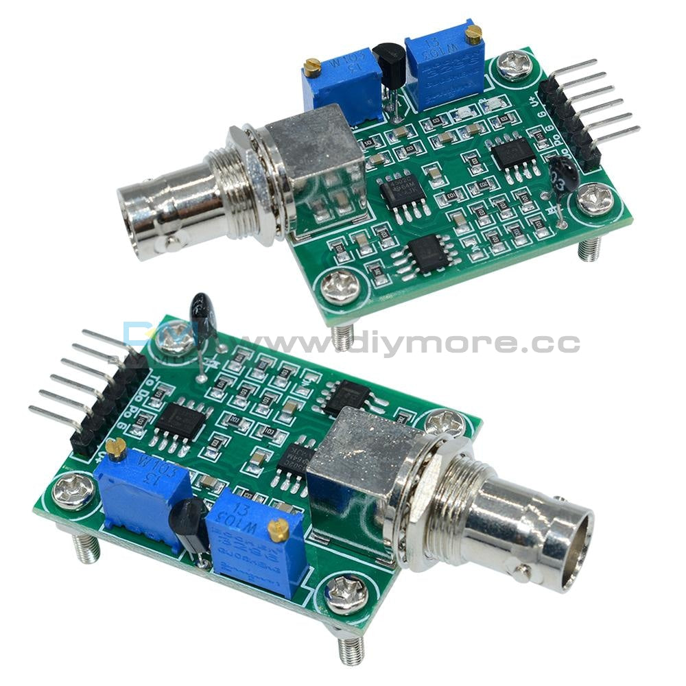
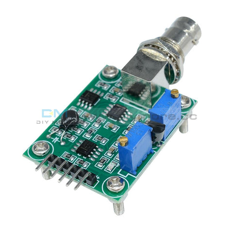 Translation missing: en.products.product.regular_price $12.99{"id":4419938418759,"title":"Arduino 2A H-Bridge Dual Channel DC Motor Driver Shield Module L298NH Than L298P","handle":"replace-l298p-for-arduino-uno-r3-dual-channel-dc-motor-driver-shield-expansion-board-l298nh-module-driving-module-mega2560-one","description":"\u003cdiv\u003e\n\u003cwidget data-widget-type=\"customText\" id=\"33684419\" title=\"Head\" type=\"custom\"\u003e\u003c\/widget\u003e \r \u003cp\u003e\u003cspan style=\"font-size: 16.0px;font-family: trebuchet ms;\"\u003e \u003c\/span\u003e\u003c\/p\u003e \r \u003cdiv\u003e \r \u003cspan style=\"font-size: 16.0px;font-family: trebuchet ms;\"\u003e \u003c\/span\u003e \r \u003cp\u003e\u003cimg src=\"https:\/\/ae01.alicdn.com\/kf\/HTB12JMgilsmBKNjSZFsq6yXSVXaS.jpg\"\u003e\u003c\/p\u003e \r \u003c\/div\u003e \r \u003cdiv\u003e \r \u003cp\u003e\u003cbr\u003e\u003c\/p\u003e \r \u003c\/div\u003e \r \u003cdiv\u003e \r \u003cspan style=\"font-size: 16.0px;font-family: trebuchet ms;\"\u003e \u003c\/span\u003e \r \u003c\/div\u003e \r \u003cdiv\u003e \r \u003cspan style=\"font-size: 16.0px;font-family: trebuchet ms;\"\u003e\u003cspan style=\"font-size: 16.0px;font-family: trebuchet ms;\"\u003eThe Motor Shield is based on the L298NH, which is a dual full-bridge driver designed to drive inductive loads such as relays, solenoids, DC and stepping motors. It lets you drive two DC motors with your for arduino board, controlling the speed and direction of each one independently. You can also measure the motor current absorption of each motor, among other features. \u003c\/span\u003e\u003c\/span\u003e \r \u003c\/div\u003e \r \u003cdiv\u003e \r \u003cspan style=\"font-size: 16.0px;font-family: trebuchet ms;\"\u003e\u003cspan style=\"font-size: 16.0px;font-family: trebuchet ms;\"\u003e•You can find in the Getting Started section all the information you need to configure your board, use the for arduino Software (IDE), and start tinker with coding and electronics. \u003c\/span\u003e\u003c\/span\u003e \r \u003c\/div\u003e \r \u003cdiv\u003e \r \u003cspan style=\"font-size: 16.0px;font-family: trebuchet ms;\"\u003e \u003c\/span\u003e \r \u003c\/div\u003e \r \u003cdiv\u003e \r \u003cspan style=\"font-size: 16.0px;font-family: trebuchet ms;color: #ff6600;\"\u003e\u003cspan style=\"font-size: 16.0px;font-family: trebuchet ms;color: #ff6600;\"\u003e\u003cstrong\u003eTechnical specs\u003c\/strong\u003e\u003c\/span\u003e\u003c\/span\u003e \r \u003c\/div\u003e \r \u003cdiv\u003e \r \u003cspan style=\"font-size: 16.0px;\"\u003e\u003cspan style=\"font-family: trebuchet ms , helvetica , sans-serif;\"\u003e\u003cspan style=\"font-size: 16.0px;font-family: trebuchet ms;\"\u003eOperating Voltage\u003c\/span\u003e\u003cspan style=\"font-size: 16.0px;font-family: trebuchet ms;\"\u003e \u003c\/span\u003e\u003cspan style=\"font-size: 16.0px;font-family: trebuchet ms;\"\u003e5V to 12V\u003c\/span\u003e\u003c\/span\u003e\u003c\/span\u003e \r \u003c\/div\u003e \r \u003cdiv\u003e \r \u003cspan style=\"font-size: 16.0px;\"\u003e\u003cspan style=\"font-family: trebuchet ms , helvetica , sans-serif;\"\u003e\u003cspan style=\"font-size: 16.0px;font-family: trebuchet ms;\"\u003eMotor controller \u003c\/span\u003e\u003cspan style=\"font-size: 16.0px;font-family: trebuchet ms;\"\u003e \u003c\/span\u003e\u003cspan style=\"font-size: 16.0px;font-family: trebuchet ms;\"\u003eL298HN, Drives 2 DC motors or 1 stepper motor\u003c\/span\u003e\u003c\/span\u003e\u003c\/span\u003e \r \u003c\/div\u003e \r \u003cdiv\u003e \r \u003cspan style=\"font-size: 16.0px;\"\u003e\u003cspan style=\"font-family: trebuchet ms , helvetica , sans-serif;\"\u003e\u003cspan style=\"font-size: 16.0px;font-family: trebuchet ms;\"\u003eMax current\u003c\/span\u003e\u003cspan style=\"font-size: 16.0px;font-family: trebuchet ms;\"\u003e \u003c\/span\u003e\u003cspan style=\"font-size: 16.0px;font-family: trebuchet ms;\"\u003e2A per channel or 4A max (with external power supply)\u003c\/span\u003e\u003c\/span\u003e\u003c\/span\u003e \r \u003c\/div\u003e \r \u003cdiv\u003e \r \u003cspan style=\"font-size: 16.0px;\"\u003e\u003cspan style=\"font-family: trebuchet ms , helvetica , sans-serif;\"\u003e\u003cspan style=\"font-size: 16.0px;font-family: trebuchet ms;\"\u003eCurrent sensing\u003c\/span\u003e\u003cspan style=\"font-size: 16.0px;font-family: trebuchet ms;\"\u003e \u003c\/span\u003e\u003cspan style=\"font-size: 16.0px;font-family: trebuchet ms;\"\u003e1.65V\/A\u003c\/span\u003e\u003c\/span\u003e\u003c\/span\u003e \r \u003c\/div\u003e \r \u003cdiv\u003e \r \u003cspan style=\"font-size: 16.0px;font-family: trebuchet ms;\"\u003e\u003cspan style=\"font-size: 16.0px;font-family: trebuchet ms;\"\u003e\u003cspan style=\"font-size: 16.0px;font-family: trebuchet ms;\"\u003eFree running stop and brake function\u003c\/span\u003e\u003c\/span\u003e\u003c\/span\u003e \r \u003c\/div\u003e \r \u003cdiv\u003e \r \u003cspan style=\"font-size: 16.0px;font-family: trebuchet ms;\"\u003e \u003c\/span\u003e \r \u003c\/div\u003e \r \u003cdiv\u003e \r \u003cspan style=\"font-size: 16.0px;font-family: trebuchet ms;color: #ff6600;\"\u003e\u003cspan style=\"font-size: 16.0px;font-family: trebuchet ms;color: #ff6600;\"\u003e\u003cstrong\u003ePower\u003c\/strong\u003e\u003c\/span\u003e\u003c\/span\u003e \r \u003c\/div\u003e \r \u003cdiv\u003e \r \u003cspan style=\"font-size: 16.0px;font-family: trebuchet ms;\"\u003e \u003c\/span\u003e \r \u003c\/div\u003e \r \u003cdiv\u003e \r \u003cspan style=\"font-size: 16.0px;font-family: trebuchet ms;\"\u003e\u003cspan style=\"font-size: 16.0px;font-family: trebuchet ms;\"\u003eThe Motor Shield must be powered only by an external power supply. Because the L298HN IC mounted on the shield has two separate power connections, one for the logic and one for the motor supply driver. The required motor current often exceeds the maximum USB current rating.\u003c\/span\u003e\u003c\/span\u003e \r \u003c\/div\u003e \r \u003cdiv\u003e \r \u003cspan style=\"font-size: 16.0px;font-family: trebuchet ms;\"\u003e\u003cspan style=\"font-size: 16.0px;font-family: trebuchet ms;\"\u003eExternal (non-USB) power can come either from an AC-to-DC adapter (wall-wart) or battery. The adapter can be connected by plugging a 2.1mm center-positive plug into the for arduino 's board power jack on which the motor shield is mounted or by connecting the wires that lead the power supply to the Vin and GND screw terminals, taking care to respect the polarities.\u003c\/span\u003e\u003c\/span\u003e \r \u003c\/div\u003e \r \u003cdiv\u003e \r \u003cspan style=\"font-size: 16.0px;font-family: trebuchet ms;\"\u003e\u003cspan style=\"font-size: 16.0px;font-family: trebuchet ms;\"\u003eTo avoid possible damage to the for arduino board on which the shield is mounted, we reccomend using an external power supply that provides a voltage between 7 and 12V. If your motor require more than 9V we recommend that you separate the power lines of the shield and the for arduino board on which the shield is mounted. This is possible by cutting the \"Vin Connect\" jumper placed on the back side of the shield. The absolute limit for the Vin at the screw terminals is 18V.\u003c\/span\u003e\u003c\/span\u003e \r \u003c\/div\u003e \r \u003cdiv\u003e \r \u003cspan style=\"font-size: 16.0px;font-family: trebuchet ms;\"\u003e\u003cspan style=\"font-size: 16.0px;font-family: trebuchet ms;\"\u003eThe shield can supply 2 amperes per channel, for a total of 4 amperes maximum. \u003c\/span\u003e\u003c\/span\u003e \r \u003c\/div\u003e \r \u003cdiv\u003e \r \u003cspan style=\"font-size: 16.0px;font-family: trebuchet ms;\"\u003e \u003c\/span\u003e \r \u003c\/div\u003e \r \u003cdiv\u003e \r \u003cspan style=\"font-size: 16.0px;font-family: trebuchet ms;color: #ff6600;\"\u003e\u003cspan style=\"font-size: 16.0px;font-family: trebuchet ms;color: #ff6600;\"\u003e\u003cstrong\u003eInput and Output\u003c\/strong\u003e\u003c\/span\u003e\u003c\/span\u003e \r \u003c\/div\u003e \r \u003cdiv\u003e \r \u003cspan style=\"font-size: 16.0px;font-family: trebuchet ms;\"\u003e \u003c\/span\u003e \r \u003c\/div\u003e \r \u003cdiv\u003e \r \u003cspan style=\"font-size: 16.0px;font-family: trebuchet ms;\"\u003e\u003cspan style=\"font-size: 16.0px;font-family: trebuchet ms;\"\u003eThis shield has two separate channels, called A and B, that each use 4 of the for arduino pins to drive or sense the motor. In total there are 8 pins in use on this shield. You can use each channel separately to drive two DC motors or combine them to drive one bipolar stepper motor. The shield's pins, divided by channel are shown in the table below: \u003c\/span\u003e\u003c\/span\u003e \r \u003c\/div\u003e \r \u003cdiv\u003e \r \u003cspan style=\"font-size: 16.0px;font-family: trebuchet ms;\"\u003e \u003c\/span\u003e \r \u003c\/div\u003e \r \u003cdiv\u003e \r \u003cspan style=\"font-size: 16.0px;\"\u003e\u003cspan style=\"font-family: trebuchet ms , helvetica , sans-serif;\"\u003e\u003cspan style=\"font-size: 16.0px;font-family: trebuchet ms;\"\u003eFunction \u003c\/span\u003e\u003cspan style=\"font-size: 16.0px;font-family: trebuchet ms;\"\u003e \u003c\/span\u003e\u003cspan style=\"font-size: 16.0px;font-family: trebuchet ms;\"\u003epins per Ch. A\u003c\/span\u003e\u003cspan style=\"font-size: 16.0px;font-family: trebuchet ms;\"\u003e \u003c\/span\u003e\u003cspan style=\"font-size: 16.0px;font-family: trebuchet ms;\"\u003epins per Ch. B\u003c\/span\u003e\u003c\/span\u003e\u003c\/span\u003e \r \u003c\/div\u003e \r \u003cdiv\u003e \r \u003cspan style=\"font-size: 16.0px;\"\u003e\u003cspan style=\"font-family: trebuchet ms , helvetica , sans-serif;\"\u003e\u003cspan style=\"font-size: 16.0px;font-family: trebuchet ms;\"\u003eDirection\u003c\/span\u003e\u003cspan style=\"font-size: 16.0px;font-family: trebuchet ms;\"\u003e \u003c\/span\u003e\u003cspan style=\"font-size: 16.0px;font-family: trebuchet ms;\"\u003eD12\u003c\/span\u003e\u003cspan style=\"font-size: 16.0px;font-family: trebuchet ms;\"\u003e \u003c\/span\u003e\u003cspan style=\"font-size: 16.0px;font-family: trebuchet ms;\"\u003eD13\u003c\/span\u003e\u003c\/span\u003e\u003c\/span\u003e \r \u003c\/div\u003e \r \u003cdiv\u003e \r \u003cspan style=\"font-size: 16.0px;\"\u003e\u003cspan style=\"font-family: trebuchet ms , helvetica , sans-serif;\"\u003e\u003cspan style=\"font-size: 16.0px;font-family: trebuchet ms;\"\u003ePWM\u003c\/span\u003e\u003cspan style=\"font-size: 16.0px;font-family: trebuchet ms;\"\u003e \u003c\/span\u003e\u003cspan style=\"font-size: 16.0px;font-family: trebuchet ms;\"\u003eD3\u003c\/span\u003e\u003cspan style=\"font-size: 16.0px;font-family: trebuchet ms;\"\u003e \u003c\/span\u003e\u003cspan style=\"font-size: 16.0px;font-family: trebuchet ms;\"\u003eD11\u003c\/span\u003e\u003c\/span\u003e\u003c\/span\u003e \r \u003c\/div\u003e \r \u003cdiv\u003e \r \u003cspan style=\"font-size: 16.0px;\"\u003e\u003cspan style=\"font-family: trebuchet ms , helvetica , sans-serif;\"\u003e\u003cspan style=\"font-size: 16.0px;font-family: trebuchet ms;\"\u003eBrake\u003c\/span\u003e\u003cspan style=\"font-size: 16.0px;font-family: trebuchet ms;\"\u003e \u003c\/span\u003e\u003cspan style=\"font-size: 16.0px;font-family: trebuchet ms;\"\u003eD9\u003c\/span\u003e\u003cspan style=\"font-size: 16.0px;font-family: trebuchet ms;\"\u003e \u003c\/span\u003e\u003cspan style=\"font-size: 16.0px;font-family: trebuchet ms;\"\u003eD8\u003c\/span\u003e\u003c\/span\u003e\u003c\/span\u003e \r \u003c\/div\u003e \r \u003cdiv\u003e \r \u003cspan style=\"font-size: 16.0px;\"\u003e\u003cspan style=\"font-family: trebuchet ms , helvetica , sans-serif;\"\u003e\u003cspan style=\"font-size: 16.0px;font-family: trebuchet ms;\"\u003eCurrent Sensing\u003c\/span\u003e\u003cspan style=\"font-size: 16.0px;font-family: trebuchet ms;\"\u003e \u003c\/span\u003e\u003cspan style=\"font-size: 16.0px;font-family: trebuchet ms;\"\u003eA0 \u003c\/span\u003e\u003cspan style=\"font-size: 16.0px;font-family: trebuchet ms;\"\u003e \u003c\/span\u003e\u003cspan style=\"font-size: 16.0px;font-family: trebuchet ms;\"\u003eA1\u003c\/span\u003e\u003c\/span\u003e\u003c\/span\u003e \r \u003c\/div\u003e \r \u003cdiv\u003e \r \u003cspan style=\"font-size: 16.0px;font-family: trebuchet ms;\"\u003e \u003c\/span\u003e \r \u003c\/div\u003e \r \u003cdiv\u003e \r \u003cspan style=\"font-size: 16.0px;font-family: trebuchet ms;\"\u003e\u003cspan style=\"font-size: 16.0px;font-family: trebuchet ms;\"\u003eIf you don't need the Brake and the Current Sensing and you also need more pins for your application you can disable this features by cutting the respective jumpers on the back side of the shield. \u003c\/span\u003e\u003c\/span\u003e \r \u003c\/div\u003e \r \u003cdiv\u003e \r \u003cspan style=\"font-size: 16.0px;font-family: trebuchet ms;\"\u003e \u003c\/span\u003e \r \u003c\/div\u003e \r \u003cdiv\u003e \r \u003cspan style=\"font-size: 16.0px;font-family: trebuchet ms;color: #ff6600;\"\u003e\u003cspan style=\"font-size: 16.0px;font-family: trebuchet ms;color: #ff6600;\"\u003e\u003cstrong\u003eMotors Connection\u003c\/strong\u003e\u003c\/span\u003e\u003c\/span\u003e \r \u003c\/div\u003e \r \u003cdiv\u003e \r \u003cspan style=\"font-size: 16.0px;font-family: trebuchet ms;\"\u003e\u003cspan style=\"font-size: 16.0px;font-family: trebuchet ms;\"\u003eBrushed DC motor. You can drive two Brushed DC motors by connecting the two wires of each one in the (+) and (-) screw terminals for each channel A and B. In this way you can control its direction by setting HIGH or LOW the DIR A and DIR B pins, you can control the speed by varying the PWM A and PWM B duty cycle values. The Brake A and Brake B pins, if set HIGH, will effectively brake the DC motors rather than let them slow down by cutting the power. You can measure the current going through the DC motor by reading the SNS0 and SNS1 pins. On each channel will be a voltage proportional to the measured current, which can be read as a normal analog input, through the function analogRead() on the analog input A0 and A1. For your convenience it is calibrated to be 3.3V when the channel is delivering its maximum possible current, that is 2A. \u003c\/span\u003e\u003c\/span\u003e \r \u003c\/div\u003e \r \u003cdiv\u003e \r \u003cspan style=\"font-size: 16.0px;font-family: trebuchet ms;\"\u003e \u003c\/span\u003e \r \u003c\/div\u003e \r \u003cdiv\u003e \r \u003cspan style=\"font-size: 16.0px;font-family: trebuchet ms;\"\u003e \u003c\/span\u003e \r \u003c\/div\u003e \r \u003cdiv\u003e \r \u003cspan style=\"font-size: 16.0px;font-family: trebuchet ms;\"\u003e \u003c\/span\u003e \r \u003c\/div\u003e \r \u003cdiv\u003e \r \u003cspan style=\"font-size: 16.0px;font-family: trebuchet ms;\"\u003e \u003c\/span\u003e \r \u003c\/div\u003e \r \u003cdiv\u003e \r \u003cspan style=\"font-size: 16.0px;font-family: trebuchet ms;color: #ff6600;\"\u003e\u003cstrong\u003e \u003c\/strong\u003e\u003c\/span\u003e \r \u003cspan style=\"font-size: 16.0px;font-family: trebuchet ms;color: #ff6600;\"\u003e\u003cspan style=\"font-size: 16.0px;font-family: trebuchet ms;color: #ff6600;\"\u003e\u003cstrong\u003ePackage Included:\u003c\/strong\u003e\u003c\/span\u003e\u003c\/span\u003e \r \u003c\/div\u003e \r \u003cdiv\u003e \r \u003cspan style=\"font-size: 16.0px;font-family: trebuchet ms;\"\u003e \u003c\/span\u003e \r \u003c\/div\u003e \r \u003cdiv\u003e \r \u003cspan style=\"font-size: 16.0px;font-family: trebuchet ms;\"\u003e 1 x L298NH Dual Channel DC Motor Driver Shield Board\u003c\/span\u003e \r \u003c\/div\u003e \r \u003cp\u003e\u003cspan style=\"font-size: 16.0px;font-family: trebuchet ms;\"\u003e \u003c\/span\u003e\u003c\/p\u003e \r \u003cp\u003e\u003cspan style=\"font-size: 16.0px;font-family: trebuchet ms;\"\u003e \u003c\/span\u003e\u003c\/p\u003e \r \u003cspan style=\"font-size: 16.0px;font-family: trebuchet ms;\"\u003e \u003cp\u003e\u003cimg src=\"https:\/\/ae01.alicdn.com\/kf\/HTB1VXjubuUXBuNjt_a0q6AysXXaA.jpg\"\u003e\u003c\/p\u003e\n\u003cp\u003e \u003c\/p\u003e\n\u003cp\u003e\u003cimg style=\"width: 1000.0px;\" src=\"https:\/\/ae01.alicdn.com\/kf\/HTB1acVFa6vuK1Rjy0Faq6x2aVXaR.jpg\"\u003e\u003c\/p\u003e\n\u003cp\u003e\u003cimg style=\"width: 1000.0px;\" src=\"https:\/\/ae01.alicdn.com\/kf\/HTB14yJHa.rrK1RkSne1q6ArVVXaJ.jpg\"\u003e\u003c\/p\u003e\n\u003cp\u003e\u003cbr\u003e\u003c\/p\u003e\n\u003cp\u003e\u003cimg style=\"width: 1000.0px;\" src=\"https:\/\/ae01.alicdn.com\/kf\/HTB1VvpAa.vrK1RjSszfq6xJNVXat.jpg\"\u003e\u003c\/p\u003e\n\u003cp\u003e\u003cimg style=\"width: 1000.0px;\" src=\"https:\/\/ae01.alicdn.com\/kf\/HTB1yj5TaPLuK1Rjy0Fhq6xpdFXa6.jpg\"\u003e\u003c\/p\u003e\n\u003cp\u003e\u003cimg style=\"width: 1000.0px;\" src=\"https:\/\/ae01.alicdn.com\/kf\/HTB1WhJCa5DxK1Rjy1zcq6yGeXXai.jpg\"\u003e\u003c\/p\u003e\n\u003cp\u003e \u003c\/p\u003e\n\u003cp\u003e\u003cimg src=\"https:\/\/ae01.alicdn.com\/kf\/HTB1Hc.uimcqBKNjSZFgq6x_kXXaq.jpg\"\u003e\u003c\/p\u003e\n\u003cp\u003e \u003c\/p\u003e\n\u003cp\u003e \r \u003cwidget data-widget-type=\"customText\" id=\"24006699\" title=\"Related\" type=\"custom\"\u003e\u003c\/widget\u003e \u003c\/p\u003e\u003c\/span\u003e \r \u003cp\u003e\u003c\/p\u003e \r \u003cp\u003e\u003cspan style=\"font-size: 16.0px;font-family: trebuchet ms;\"\u003e \u003c\/span\u003e\u003c\/p\u003e \u003cscript\u003ewindow.adminAccountId=227552571;\u003c\/script\u003e \u003c\/div\u003e","published_at":"2019-12-27T16:28:18+08:00","created_at":"2019-12-27T16:28:30+08:00","vendor":"diymore","type":"Integrated Circuits","tags":[],"price":899,"price_min":899,"price_max":899,"available":true,"price_varies":false,"compare_at_price":null,"compare_at_price_min":0,"compare_at_price_max":0,"compare_at_price_varies":false,"variants":[{"id":31582607409223,"title":"Default Title","option1":"Default Title","option2":null,"option3":null,"sku":"180030","requires_shipping":true,"taxable":true,"featured_image":null,"available":true,"name":"Arduino 2A H-Bridge Dual Channel DC Motor Driver Shield Module L298NH Than L298P","public_title":null,"options":["Default Title"],"price":899,"weight":30,"compare_at_price":null,"inventory_management":null,"barcode":"","requires_selling_plan":false,"selling_plan_allocations":[],"quantity_rule":{"min":1,"max":null,"increment":1}}],"images":["\/\/www.diymore.cc\/cdn\/shop\/products\/Replace-L298P-For-Arduino-UNO-R3-Dual-Channel-DC-Motor-Driver-Shield-Expansion-Board-L298NH-Module_259.jpg?v=1588697940","\/\/www.diymore.cc\/cdn\/shop\/products\/Replace-L298P-For-Arduino-UNO-R3-Dual-Channel-DC-Motor-Driver-Shield-Expansion-Board-L298NH-Module_63b77384-930b-4e89-8b62-17bdb7ff23c5_644.jpg?v=1588697940","\/\/www.diymore.cc\/cdn\/shop\/products\/Replace-L298P-For-Arduino-UNO-R3-Dual-Channel-DC-Motor-Driver-Shield-Expansion-Board-L298NH-Module_0a80a83c-dc2f-460c-a034-768bd412d88c_731.jpg?v=1588697940","\/\/www.diymore.cc\/cdn\/shop\/products\/Replace-L298P-For-Arduino-UNO-R3-Dual-Channel-DC-Motor-Driver-Shield-Expansion-Board-L298NH-Module_10e0ead5-7c58-4cd0-9dbc-9e26210641df_203.jpg?v=1588697940","\/\/www.diymore.cc\/cdn\/shop\/products\/Replace-L298P-For-Arduino-UNO-R3-Dual-Channel-DC-Motor-Driver-Shield-Expansion-Board-L298NH-Module_c95cb3f4-de34-4a9e-b289-07a336bce0ef_828.jpg?v=1588697940"],"featured_image":"\/\/www.diymore.cc\/cdn\/shop\/products\/Replace-L298P-For-Arduino-UNO-R3-Dual-Channel-DC-Motor-Driver-Shield-Expansion-Board-L298NH-Module_259.jpg?v=1588697940","options":["Title"],"media":[{"alt":"Replace L298P For Arduino Uno R3 Dual Channel Dc Motor Driver Shield Expansion Board L298Nh Module","id":6682319224903,"position":1,"preview_image":{"aspect_ratio":1.0,"height":1000,"width":1000,"src":"\/\/www.diymore.cc\/cdn\/shop\/products\/Replace-L298P-For-Arduino-UNO-R3-Dual-Channel-DC-Motor-Driver-Shield-Expansion-Board-L298NH-Module_259.jpg?v=1588697940"},"aspect_ratio":1.0,"height":1000,"media_type":"image","src":"\/\/www.diymore.cc\/cdn\/shop\/products\/Replace-L298P-For-Arduino-UNO-R3-Dual-Channel-DC-Motor-Driver-Shield-Expansion-Board-L298NH-Module_259.jpg?v=1588697940","width":1000},{"alt":"Replace L298P For Arduino Uno R3 Dual Channel Dc Motor Driver Shield Expansion Board L298Nh Module","id":6682319355975,"position":2,"preview_image":{"aspect_ratio":1.0,"height":1000,"width":1000,"src":"\/\/www.diymore.cc\/cdn\/shop\/products\/Replace-L298P-For-Arduino-UNO-R3-Dual-Channel-DC-Motor-Driver-Shield-Expansion-Board-L298NH-Module_63b77384-930b-4e89-8b62-17bdb7ff23c5_644.jpg?v=1588697940"},"aspect_ratio":1.0,"height":1000,"media_type":"image","src":"\/\/www.diymore.cc\/cdn\/shop\/products\/Replace-L298P-For-Arduino-UNO-R3-Dual-Channel-DC-Motor-Driver-Shield-Expansion-Board-L298NH-Module_63b77384-930b-4e89-8b62-17bdb7ff23c5_644.jpg?v=1588697940","width":1000},{"alt":"Replace L298P For Arduino Uno R3 Dual Channel Dc Motor Driver Shield Expansion Board L298Nh Module","id":6682319585351,"position":3,"preview_image":{"aspect_ratio":1.0,"height":1000,"width":1000,"src":"\/\/www.diymore.cc\/cdn\/shop\/products\/Replace-L298P-For-Arduino-UNO-R3-Dual-Channel-DC-Motor-Driver-Shield-Expansion-Board-L298NH-Module_0a80a83c-dc2f-460c-a034-768bd412d88c_731.jpg?v=1588697940"},"aspect_ratio":1.0,"height":1000,"media_type":"image","src":"\/\/www.diymore.cc\/cdn\/shop\/products\/Replace-L298P-For-Arduino-UNO-R3-Dual-Channel-DC-Motor-Driver-Shield-Expansion-Board-L298NH-Module_0a80a83c-dc2f-460c-a034-768bd412d88c_731.jpg?v=1588697940","width":1000},{"alt":"Replace L298P For Arduino Uno R3 Dual Channel Dc Motor Driver Shield Expansion Board L298Nh Module","id":6682319716423,"position":4,"preview_image":{"aspect_ratio":1.0,"height":1000,"width":1000,"src":"\/\/www.diymore.cc\/cdn\/shop\/products\/Replace-L298P-For-Arduino-UNO-R3-Dual-Channel-DC-Motor-Driver-Shield-Expansion-Board-L298NH-Module_10e0ead5-7c58-4cd0-9dbc-9e26210641df_203.jpg?v=1588697940"},"aspect_ratio":1.0,"height":1000,"media_type":"image","src":"\/\/www.diymore.cc\/cdn\/shop\/products\/Replace-L298P-For-Arduino-UNO-R3-Dual-Channel-DC-Motor-Driver-Shield-Expansion-Board-L298NH-Module_10e0ead5-7c58-4cd0-9dbc-9e26210641df_203.jpg?v=1588697940","width":1000},{"alt":"Replace L298P For Arduino Uno R3 Dual Channel Dc Motor Driver Shield Expansion Board L298Nh Module","id":6682319781959,"position":5,"preview_image":{"aspect_ratio":1.0,"height":1000,"width":1000,"src":"\/\/www.diymore.cc\/cdn\/shop\/products\/Replace-L298P-For-Arduino-UNO-R3-Dual-Channel-DC-Motor-Driver-Shield-Expansion-Board-L298NH-Module_c95cb3f4-de34-4a9e-b289-07a336bce0ef_828.jpg?v=1588697940"},"aspect_ratio":1.0,"height":1000,"media_type":"image","src":"\/\/www.diymore.cc\/cdn\/shop\/products\/Replace-L298P-For-Arduino-UNO-R3-Dual-Channel-DC-Motor-Driver-Shield-Expansion-Board-L298NH-Module_c95cb3f4-de34-4a9e-b289-07a336bce0ef_828.jpg?v=1588697940","width":1000}],"requires_selling_plan":false,"selling_plan_groups":[],"content":"\u003cdiv\u003e\n\u003cwidget data-widget-type=\"customText\" id=\"33684419\" title=\"Head\" type=\"custom\"\u003e\u003c\/widget\u003e \r \u003cp\u003e\u003cspan style=\"font-size: 16.0px;font-family: trebuchet ms;\"\u003e \u003c\/span\u003e\u003c\/p\u003e \r \u003cdiv\u003e \r \u003cspan style=\"font-size: 16.0px;font-family: trebuchet ms;\"\u003e \u003c\/span\u003e \r \u003cp\u003e\u003cimg src=\"https:\/\/ae01.alicdn.com\/kf\/HTB12JMgilsmBKNjSZFsq6yXSVXaS.jpg\"\u003e\u003c\/p\u003e \r \u003c\/div\u003e \r \u003cdiv\u003e \r \u003cp\u003e\u003cbr\u003e\u003c\/p\u003e \r \u003c\/div\u003e \r \u003cdiv\u003e \r \u003cspan style=\"font-size: 16.0px;font-family: trebuchet ms;\"\u003e \u003c\/span\u003e \r \u003c\/div\u003e \r \u003cdiv\u003e \r \u003cspan style=\"font-size: 16.0px;font-family: trebuchet ms;\"\u003e\u003cspan style=\"font-size: 16.0px;font-family: trebuchet ms;\"\u003eThe Motor Shield is based on the L298NH, which is a dual full-bridge driver designed to drive inductive loads such as relays, solenoids, DC and stepping motors. It lets you drive two DC motors with your for arduino board, controlling the speed and direction of each one independently. You can also measure the motor current absorption of each motor, among other features. \u003c\/span\u003e\u003c\/span\u003e \r \u003c\/div\u003e \r \u003cdiv\u003e \r \u003cspan style=\"font-size: 16.0px;font-family: trebuchet ms;\"\u003e\u003cspan style=\"font-size: 16.0px;font-family: trebuchet ms;\"\u003e•You can find in the Getting Started section all the information you need to configure your board, use the for arduino Software (IDE), and start tinker with coding and electronics. \u003c\/span\u003e\u003c\/span\u003e \r \u003c\/div\u003e \r \u003cdiv\u003e \r \u003cspan style=\"font-size: 16.0px;font-family: trebuchet ms;\"\u003e \u003c\/span\u003e \r \u003c\/div\u003e \r \u003cdiv\u003e \r \u003cspan style=\"font-size: 16.0px;font-family: trebuchet ms;color: #ff6600;\"\u003e\u003cspan style=\"font-size: 16.0px;font-family: trebuchet ms;color: #ff6600;\"\u003e\u003cstrong\u003eTechnical specs\u003c\/strong\u003e\u003c\/span\u003e\u003c\/span\u003e \r \u003c\/div\u003e \r \u003cdiv\u003e \r \u003cspan style=\"font-size: 16.0px;\"\u003e\u003cspan style=\"font-family: trebuchet ms , helvetica , sans-serif;\"\u003e\u003cspan style=\"font-size: 16.0px;font-family: trebuchet ms;\"\u003eOperating Voltage\u003c\/span\u003e\u003cspan style=\"font-size: 16.0px;font-family: trebuchet ms;\"\u003e \u003c\/span\u003e\u003cspan style=\"font-size: 16.0px;font-family: trebuchet ms;\"\u003e5V to 12V\u003c\/span\u003e\u003c\/span\u003e\u003c\/span\u003e \r \u003c\/div\u003e \r \u003cdiv\u003e \r \u003cspan style=\"font-size: 16.0px;\"\u003e\u003cspan style=\"font-family: trebuchet ms , helvetica , sans-serif;\"\u003e\u003cspan style=\"font-size: 16.0px;font-family: trebuchet ms;\"\u003eMotor controller \u003c\/span\u003e\u003cspan style=\"font-size: 16.0px;font-family: trebuchet ms;\"\u003e \u003c\/span\u003e\u003cspan style=\"font-size: 16.0px;font-family: trebuchet ms;\"\u003eL298HN, Drives 2 DC motors or 1 stepper motor\u003c\/span\u003e\u003c\/span\u003e\u003c\/span\u003e \r \u003c\/div\u003e \r \u003cdiv\u003e \r \u003cspan style=\"font-size: 16.0px;\"\u003e\u003cspan style=\"font-family: trebuchet ms , helvetica , sans-serif;\"\u003e\u003cspan style=\"font-size: 16.0px;font-family: trebuchet ms;\"\u003eMax current\u003c\/span\u003e\u003cspan style=\"font-size: 16.0px;font-family: trebuchet ms;\"\u003e \u003c\/span\u003e\u003cspan style=\"font-size: 16.0px;font-family: trebuchet ms;\"\u003e2A per channel or 4A max (with external power supply)\u003c\/span\u003e\u003c\/span\u003e\u003c\/span\u003e \r \u003c\/div\u003e \r \u003cdiv\u003e \r \u003cspan style=\"font-size: 16.0px;\"\u003e\u003cspan style=\"font-family: trebuchet ms , helvetica , sans-serif;\"\u003e\u003cspan style=\"font-size: 16.0px;font-family: trebuchet ms;\"\u003eCurrent sensing\u003c\/span\u003e\u003cspan style=\"font-size: 16.0px;font-family: trebuchet ms;\"\u003e \u003c\/span\u003e\u003cspan style=\"font-size: 16.0px;font-family: trebuchet ms;\"\u003e1.65V\/A\u003c\/span\u003e\u003c\/span\u003e\u003c\/span\u003e \r \u003c\/div\u003e \r \u003cdiv\u003e \r \u003cspan style=\"font-size: 16.0px;font-family: trebuchet ms;\"\u003e\u003cspan style=\"font-size: 16.0px;font-family: trebuchet ms;\"\u003e\u003cspan style=\"font-size: 16.0px;font-family: trebuchet ms;\"\u003eFree running stop and brake function\u003c\/span\u003e\u003c\/span\u003e\u003c\/span\u003e \r \u003c\/div\u003e \r \u003cdiv\u003e \r \u003cspan style=\"font-size: 16.0px;font-family: trebuchet ms;\"\u003e \u003c\/span\u003e \r \u003c\/div\u003e \r \u003cdiv\u003e \r \u003cspan style=\"font-size: 16.0px;font-family: trebuchet ms;color: #ff6600;\"\u003e\u003cspan style=\"font-size: 16.0px;font-family: trebuchet ms;color: #ff6600;\"\u003e\u003cstrong\u003ePower\u003c\/strong\u003e\u003c\/span\u003e\u003c\/span\u003e \r \u003c\/div\u003e \r \u003cdiv\u003e \r \u003cspan style=\"font-size: 16.0px;font-family: trebuchet ms;\"\u003e \u003c\/span\u003e \r \u003c\/div\u003e \r \u003cdiv\u003e \r \u003cspan style=\"font-size: 16.0px;font-family: trebuchet ms;\"\u003e\u003cspan style=\"font-size: 16.0px;font-family: trebuchet ms;\"\u003eThe Motor Shield must be powered only by an external power supply. Because the L298HN IC mounted on the shield has two separate power connections, one for the logic and one for the motor supply driver. The required motor current often exceeds the maximum USB current rating.\u003c\/span\u003e\u003c\/span\u003e \r \u003c\/div\u003e \r \u003cdiv\u003e \r \u003cspan style=\"font-size: 16.0px;font-family: trebuchet ms;\"\u003e\u003cspan style=\"font-size: 16.0px;font-family: trebuchet ms;\"\u003eExternal (non-USB) power can come either from an AC-to-DC adapter (wall-wart) or battery. The adapter can be connected by plugging a 2.1mm center-positive plug into the for arduino 's board power jack on which the motor shield is mounted or by connecting the wires that lead the power supply to the Vin and GND screw terminals, taking care to respect the polarities.\u003c\/span\u003e\u003c\/span\u003e \r \u003c\/div\u003e \r \u003cdiv\u003e \r \u003cspan style=\"font-size: 16.0px;font-family: trebuchet ms;\"\u003e\u003cspan style=\"font-size: 16.0px;font-family: trebuchet ms;\"\u003eTo avoid possible damage to the for arduino board on which the shield is mounted, we reccomend using an external power supply that provides a voltage between 7 and 12V. If your motor require more than 9V we recommend that you separate the power lines of the shield and the for arduino board on which the shield is mounted. This is possible by cutting the \"Vin Connect\" jumper placed on the back side of the shield. The absolute limit for the Vin at the screw terminals is 18V.\u003c\/span\u003e\u003c\/span\u003e \r \u003c\/div\u003e \r \u003cdiv\u003e \r \u003cspan style=\"font-size: 16.0px;font-family: trebuchet ms;\"\u003e\u003cspan style=\"font-size: 16.0px;font-family: trebuchet ms;\"\u003eThe shield can supply 2 amperes per channel, for a total of 4 amperes maximum. \u003c\/span\u003e\u003c\/span\u003e \r \u003c\/div\u003e \r \u003cdiv\u003e \r \u003cspan style=\"font-size: 16.0px;font-family: trebuchet ms;\"\u003e \u003c\/span\u003e \r \u003c\/div\u003e \r \u003cdiv\u003e \r \u003cspan style=\"font-size: 16.0px;font-family: trebuchet ms;color: #ff6600;\"\u003e\u003cspan style=\"font-size: 16.0px;font-family: trebuchet ms;color: #ff6600;\"\u003e\u003cstrong\u003eInput and Output\u003c\/strong\u003e\u003c\/span\u003e\u003c\/span\u003e \r \u003c\/div\u003e \r \u003cdiv\u003e \r \u003cspan style=\"font-size: 16.0px;font-family: trebuchet ms;\"\u003e \u003c\/span\u003e \r \u003c\/div\u003e \r \u003cdiv\u003e \r \u003cspan style=\"font-size: 16.0px;font-family: trebuchet ms;\"\u003e\u003cspan style=\"font-size: 16.0px;font-family: trebuchet ms;\"\u003eThis shield has two separate channels, called A and B, that each use 4 of the for arduino pins to drive or sense the motor. In total there are 8 pins in use on this shield. You can use each channel separately to drive two DC motors or combine them to drive one bipolar stepper motor. The shield's pins, divided by channel are shown in the table below: \u003c\/span\u003e\u003c\/span\u003e \r \u003c\/div\u003e \r \u003cdiv\u003e \r \u003cspan style=\"font-size: 16.0px;font-family: trebuchet ms;\"\u003e \u003c\/span\u003e \r \u003c\/div\u003e \r \u003cdiv\u003e \r \u003cspan style=\"font-size: 16.0px;\"\u003e\u003cspan style=\"font-family: trebuchet ms , helvetica , sans-serif;\"\u003e\u003cspan style=\"font-size: 16.0px;font-family: trebuchet ms;\"\u003eFunction \u003c\/span\u003e\u003cspan style=\"font-size: 16.0px;font-family: trebuchet ms;\"\u003e \u003c\/span\u003e\u003cspan style=\"font-size: 16.0px;font-family: trebuchet ms;\"\u003epins per Ch. A\u003c\/span\u003e\u003cspan style=\"font-size: 16.0px;font-family: trebuchet ms;\"\u003e \u003c\/span\u003e\u003cspan style=\"font-size: 16.0px;font-family: trebuchet ms;\"\u003epins per Ch. B\u003c\/span\u003e\u003c\/span\u003e\u003c\/span\u003e \r \u003c\/div\u003e \r \u003cdiv\u003e \r \u003cspan style=\"font-size: 16.0px;\"\u003e\u003cspan style=\"font-family: trebuchet ms , helvetica , sans-serif;\"\u003e\u003cspan style=\"font-size: 16.0px;font-family: trebuchet ms;\"\u003eDirection\u003c\/span\u003e\u003cspan style=\"font-size: 16.0px;font-family: trebuchet ms;\"\u003e \u003c\/span\u003e\u003cspan style=\"font-size: 16.0px;font-family: trebuchet ms;\"\u003eD12\u003c\/span\u003e\u003cspan style=\"font-size: 16.0px;font-family: trebuchet ms;\"\u003e \u003c\/span\u003e\u003cspan style=\"font-size: 16.0px;font-family: trebuchet ms;\"\u003eD13\u003c\/span\u003e\u003c\/span\u003e\u003c\/span\u003e \r \u003c\/div\u003e \r \u003cdiv\u003e \r \u003cspan style=\"font-size: 16.0px;\"\u003e\u003cspan style=\"font-family: trebuchet ms , helvetica , sans-serif;\"\u003e\u003cspan style=\"font-size: 16.0px;font-family: trebuchet ms;\"\u003ePWM\u003c\/span\u003e\u003cspan style=\"font-size: 16.0px;font-family: trebuchet ms;\"\u003e \u003c\/span\u003e\u003cspan style=\"font-size: 16.0px;font-family: trebuchet ms;\"\u003eD3\u003c\/span\u003e\u003cspan style=\"font-size: 16.0px;font-family: trebuchet ms;\"\u003e \u003c\/span\u003e\u003cspan style=\"font-size: 16.0px;font-family: trebuchet ms;\"\u003eD11\u003c\/span\u003e\u003c\/span\u003e\u003c\/span\u003e \r \u003c\/div\u003e \r \u003cdiv\u003e \r \u003cspan style=\"font-size: 16.0px;\"\u003e\u003cspan style=\"font-family: trebuchet ms , helvetica , sans-serif;\"\u003e\u003cspan style=\"font-size: 16.0px;font-family: trebuchet ms;\"\u003eBrake\u003c\/span\u003e\u003cspan style=\"font-size: 16.0px;font-family: trebuchet ms;\"\u003e \u003c\/span\u003e\u003cspan style=\"font-size: 16.0px;font-family: trebuchet ms;\"\u003eD9\u003c\/span\u003e\u003cspan style=\"font-size: 16.0px;font-family: trebuchet ms;\"\u003e \u003c\/span\u003e\u003cspan style=\"font-size: 16.0px;font-family: trebuchet ms;\"\u003eD8\u003c\/span\u003e\u003c\/span\u003e\u003c\/span\u003e \r \u003c\/div\u003e \r \u003cdiv\u003e \r \u003cspan style=\"font-size: 16.0px;\"\u003e\u003cspan style=\"font-family: trebuchet ms , helvetica , sans-serif;\"\u003e\u003cspan style=\"font-size: 16.0px;font-family: trebuchet ms;\"\u003eCurrent Sensing\u003c\/span\u003e\u003cspan style=\"font-size: 16.0px;font-family: trebuchet ms;\"\u003e \u003c\/span\u003e\u003cspan style=\"font-size: 16.0px;font-family: trebuchet ms;\"\u003eA0 \u003c\/span\u003e\u003cspan style=\"font-size: 16.0px;font-family: trebuchet ms;\"\u003e \u003c\/span\u003e\u003cspan style=\"font-size: 16.0px;font-family: trebuchet ms;\"\u003eA1\u003c\/span\u003e\u003c\/span\u003e\u003c\/span\u003e \r \u003c\/div\u003e \r \u003cdiv\u003e \r \u003cspan style=\"font-size: 16.0px;font-family: trebuchet ms;\"\u003e \u003c\/span\u003e \r \u003c\/div\u003e \r \u003cdiv\u003e \r \u003cspan style=\"font-size: 16.0px;font-family: trebuchet ms;\"\u003e\u003cspan style=\"font-size: 16.0px;font-family: trebuchet ms;\"\u003eIf you don't need the Brake and the Current Sensing and you also need more pins for your application you can disable this features by cutting the respective jumpers on the back side of the shield. \u003c\/span\u003e\u003c\/span\u003e \r \u003c\/div\u003e \r \u003cdiv\u003e \r \u003cspan style=\"font-size: 16.0px;font-family: trebuchet ms;\"\u003e \u003c\/span\u003e \r \u003c\/div\u003e \r \u003cdiv\u003e \r \u003cspan style=\"font-size: 16.0px;font-family: trebuchet ms;color: #ff6600;\"\u003e\u003cspan style=\"font-size: 16.0px;font-family: trebuchet ms;color: #ff6600;\"\u003e\u003cstrong\u003eMotors Connection\u003c\/strong\u003e\u003c\/span\u003e\u003c\/span\u003e \r \u003c\/div\u003e \r \u003cdiv\u003e \r \u003cspan style=\"font-size: 16.0px;font-family: trebuchet ms;\"\u003e\u003cspan style=\"font-size: 16.0px;font-family: trebuchet ms;\"\u003eBrushed DC motor. You can drive two Brushed DC motors by connecting the two wires of each one in the (+) and (-) screw terminals for each channel A and B. In this way you can control its direction by setting HIGH or LOW the DIR A and DIR B pins, you can control the speed by varying the PWM A and PWM B duty cycle values. The Brake A and Brake B pins, if set HIGH, will effectively brake the DC motors rather than let them slow down by cutting the power. You can measure the current going through the DC motor by reading the SNS0 and SNS1 pins. On each channel will be a voltage proportional to the measured current, which can be read as a normal analog input, through the function analogRead() on the analog input A0 and A1. For your convenience it is calibrated to be 3.3V when the channel is delivering its maximum possible current, that is 2A. \u003c\/span\u003e\u003c\/span\u003e \r \u003c\/div\u003e \r \u003cdiv\u003e \r \u003cspan style=\"font-size: 16.0px;font-family: trebuchet ms;\"\u003e \u003c\/span\u003e \r \u003c\/div\u003e \r \u003cdiv\u003e \r \u003cspan style=\"font-size: 16.0px;font-family: trebuchet ms;\"\u003e \u003c\/span\u003e \r \u003c\/div\u003e \r \u003cdiv\u003e \r \u003cspan style=\"font-size: 16.0px;font-family: trebuchet ms;\"\u003e \u003c\/span\u003e \r \u003c\/div\u003e \r \u003cdiv\u003e \r \u003cspan style=\"font-size: 16.0px;font-family: trebuchet ms;\"\u003e \u003c\/span\u003e \r \u003c\/div\u003e \r \u003cdiv\u003e \r \u003cspan style=\"font-size: 16.0px;font-family: trebuchet ms;color: #ff6600;\"\u003e\u003cstrong\u003e \u003c\/strong\u003e\u003c\/span\u003e \r \u003cspan style=\"font-size: 16.0px;font-family: trebuchet ms;color: #ff6600;\"\u003e\u003cspan style=\"font-size: 16.0px;font-family: trebuchet ms;color: #ff6600;\"\u003e\u003cstrong\u003ePackage Included:\u003c\/strong\u003e\u003c\/span\u003e\u003c\/span\u003e \r \u003c\/div\u003e \r \u003cdiv\u003e \r \u003cspan style=\"font-size: 16.0px;font-family: trebuchet ms;\"\u003e \u003c\/span\u003e \r \u003c\/div\u003e \r \u003cdiv\u003e \r \u003cspan style=\"font-size: 16.0px;font-family: trebuchet ms;\"\u003e 1 x L298NH Dual Channel DC Motor Driver Shield Board\u003c\/span\u003e \r \u003c\/div\u003e \r \u003cp\u003e\u003cspan style=\"font-size: 16.0px;font-family: trebuchet ms;\"\u003e \u003c\/span\u003e\u003c\/p\u003e \r \u003cp\u003e\u003cspan style=\"font-size: 16.0px;font-family: trebuchet ms;\"\u003e \u003c\/span\u003e\u003c\/p\u003e \r \u003cspan style=\"font-size: 16.0px;font-family: trebuchet ms;\"\u003e \u003cp\u003e\u003cimg src=\"https:\/\/ae01.alicdn.com\/kf\/HTB1VXjubuUXBuNjt_a0q6AysXXaA.jpg\"\u003e\u003c\/p\u003e\n\u003cp\u003e \u003c\/p\u003e\n\u003cp\u003e\u003cimg style=\"width: 1000.0px;\" src=\"https:\/\/ae01.alicdn.com\/kf\/HTB1acVFa6vuK1Rjy0Faq6x2aVXaR.jpg\"\u003e\u003c\/p\u003e\n\u003cp\u003e\u003cimg style=\"width: 1000.0px;\" src=\"https:\/\/ae01.alicdn.com\/kf\/HTB14yJHa.rrK1RkSne1q6ArVVXaJ.jpg\"\u003e\u003c\/p\u003e\n\u003cp\u003e\u003cbr\u003e\u003c\/p\u003e\n\u003cp\u003e\u003cimg style=\"width: 1000.0px;\" src=\"https:\/\/ae01.alicdn.com\/kf\/HTB1VvpAa.vrK1RjSszfq6xJNVXat.jpg\"\u003e\u003c\/p\u003e\n\u003cp\u003e\u003cimg style=\"width: 1000.0px;\" src=\"https:\/\/ae01.alicdn.com\/kf\/HTB1yj5TaPLuK1Rjy0Fhq6xpdFXa6.jpg\"\u003e\u003c\/p\u003e\n\u003cp\u003e\u003cimg style=\"width: 1000.0px;\" src=\"https:\/\/ae01.alicdn.com\/kf\/HTB1WhJCa5DxK1Rjy1zcq6yGeXXai.jpg\"\u003e\u003c\/p\u003e\n\u003cp\u003e \u003c\/p\u003e\n\u003cp\u003e\u003cimg src=\"https:\/\/ae01.alicdn.com\/kf\/HTB1Hc.uimcqBKNjSZFgq6x_kXXaq.jpg\"\u003e\u003c\/p\u003e\n\u003cp\u003e \u003c\/p\u003e\n\u003cp\u003e \r \u003cwidget data-widget-type=\"customText\" id=\"24006699\" title=\"Related\" type=\"custom\"\u003e\u003c\/widget\u003e \u003c\/p\u003e\u003c\/span\u003e \r \u003cp\u003e\u003c\/p\u003e \r \u003cp\u003e\u003cspan style=\"font-size: 16.0px;font-family: trebuchet ms;\"\u003e \u003c\/span\u003e\u003c\/p\u003e \u003cscript\u003ewindow.adminAccountId=227552571;\u003c\/script\u003e \u003c\/div\u003e"}
 -
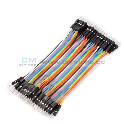 Translation missing: en.products.product.regular_price $5.99{"id":4419938418759,"title":"Arduino 2A H-Bridge Dual Channel DC Motor Driver Shield Module L298NH Than L298P","handle":"replace-l298p-for-arduino-uno-r3-dual-channel-dc-motor-driver-shield-expansion-board-l298nh-module-driving-module-mega2560-one","description":"\u003cdiv\u003e\n\u003cwidget data-widget-type=\"customText\" id=\"33684419\" title=\"Head\" type=\"custom\"\u003e\u003c\/widget\u003e \r \u003cp\u003e\u003cspan style=\"font-size: 16.0px;font-family: trebuchet ms;\"\u003e \u003c\/span\u003e\u003c\/p\u003e \r \u003cdiv\u003e \r \u003cspan style=\"font-size: 16.0px;font-family: trebuchet ms;\"\u003e \u003c\/span\u003e \r \u003cp\u003e\u003cimg src=\"https:\/\/ae01.alicdn.com\/kf\/HTB12JMgilsmBKNjSZFsq6yXSVXaS.jpg\"\u003e\u003c\/p\u003e \r \u003c\/div\u003e \r \u003cdiv\u003e \r \u003cp\u003e\u003cbr\u003e\u003c\/p\u003e \r \u003c\/div\u003e \r \u003cdiv\u003e \r \u003cspan style=\"font-size: 16.0px;font-family: trebuchet ms;\"\u003e \u003c\/span\u003e \r \u003c\/div\u003e \r \u003cdiv\u003e \r \u003cspan style=\"font-size: 16.0px;font-family: trebuchet ms;\"\u003e\u003cspan style=\"font-size: 16.0px;font-family: trebuchet ms;\"\u003eThe Motor Shield is based on the L298NH, which is a dual full-bridge driver designed to drive inductive loads such as relays, solenoids, DC and stepping motors. It lets you drive two DC motors with your for arduino board, controlling the speed and direction of each one independently. You can also measure the motor current absorption of each motor, among other features. \u003c\/span\u003e\u003c\/span\u003e \r \u003c\/div\u003e \r \u003cdiv\u003e \r \u003cspan style=\"font-size: 16.0px;font-family: trebuchet ms;\"\u003e\u003cspan style=\"font-size: 16.0px;font-family: trebuchet ms;\"\u003e•You can find in the Getting Started section all the information you need to configure your board, use the for arduino Software (IDE), and start tinker with coding and electronics. \u003c\/span\u003e\u003c\/span\u003e \r \u003c\/div\u003e \r \u003cdiv\u003e \r \u003cspan style=\"font-size: 16.0px;font-family: trebuchet ms;\"\u003e \u003c\/span\u003e \r \u003c\/div\u003e \r \u003cdiv\u003e \r \u003cspan style=\"font-size: 16.0px;font-family: trebuchet ms;color: #ff6600;\"\u003e\u003cspan style=\"font-size: 16.0px;font-family: trebuchet ms;color: #ff6600;\"\u003e\u003cstrong\u003eTechnical specs\u003c\/strong\u003e\u003c\/span\u003e\u003c\/span\u003e \r \u003c\/div\u003e \r \u003cdiv\u003e \r \u003cspan style=\"font-size: 16.0px;\"\u003e\u003cspan style=\"font-family: trebuchet ms , helvetica , sans-serif;\"\u003e\u003cspan style=\"font-size: 16.0px;font-family: trebuchet ms;\"\u003eOperating Voltage\u003c\/span\u003e\u003cspan style=\"font-size: 16.0px;font-family: trebuchet ms;\"\u003e \u003c\/span\u003e\u003cspan style=\"font-size: 16.0px;font-family: trebuchet ms;\"\u003e5V to 12V\u003c\/span\u003e\u003c\/span\u003e\u003c\/span\u003e \r \u003c\/div\u003e \r \u003cdiv\u003e \r \u003cspan style=\"font-size: 16.0px;\"\u003e\u003cspan style=\"font-family: trebuchet ms , helvetica , sans-serif;\"\u003e\u003cspan style=\"font-size: 16.0px;font-family: trebuchet ms;\"\u003eMotor controller \u003c\/span\u003e\u003cspan style=\"font-size: 16.0px;font-family: trebuchet ms;\"\u003e \u003c\/span\u003e\u003cspan style=\"font-size: 16.0px;font-family: trebuchet ms;\"\u003eL298HN, Drives 2 DC motors or 1 stepper motor\u003c\/span\u003e\u003c\/span\u003e\u003c\/span\u003e \r \u003c\/div\u003e \r \u003cdiv\u003e \r \u003cspan style=\"font-size: 16.0px;\"\u003e\u003cspan style=\"font-family: trebuchet ms , helvetica , sans-serif;\"\u003e\u003cspan style=\"font-size: 16.0px;font-family: trebuchet ms;\"\u003eMax current\u003c\/span\u003e\u003cspan style=\"font-size: 16.0px;font-family: trebuchet ms;\"\u003e \u003c\/span\u003e\u003cspan style=\"font-size: 16.0px;font-family: trebuchet ms;\"\u003e2A per channel or 4A max (with external power supply)\u003c\/span\u003e\u003c\/span\u003e\u003c\/span\u003e \r \u003c\/div\u003e \r \u003cdiv\u003e \r \u003cspan style=\"font-size: 16.0px;\"\u003e\u003cspan style=\"font-family: trebuchet ms , helvetica , sans-serif;\"\u003e\u003cspan style=\"font-size: 16.0px;font-family: trebuchet ms;\"\u003eCurrent sensing\u003c\/span\u003e\u003cspan style=\"font-size: 16.0px;font-family: trebuchet ms;\"\u003e \u003c\/span\u003e\u003cspan style=\"font-size: 16.0px;font-family: trebuchet ms;\"\u003e1.65V\/A\u003c\/span\u003e\u003c\/span\u003e\u003c\/span\u003e \r \u003c\/div\u003e \r \u003cdiv\u003e \r \u003cspan style=\"font-size: 16.0px;font-family: trebuchet ms;\"\u003e\u003cspan style=\"font-size: 16.0px;font-family: trebuchet ms;\"\u003e\u003cspan style=\"font-size: 16.0px;font-family: trebuchet ms;\"\u003eFree running stop and brake function\u003c\/span\u003e\u003c\/span\u003e\u003c\/span\u003e \r \u003c\/div\u003e \r \u003cdiv\u003e \r \u003cspan style=\"font-size: 16.0px;font-family: trebuchet ms;\"\u003e \u003c\/span\u003e \r \u003c\/div\u003e \r \u003cdiv\u003e \r \u003cspan style=\"font-size: 16.0px;font-family: trebuchet ms;color: #ff6600;\"\u003e\u003cspan style=\"font-size: 16.0px;font-family: trebuchet ms;color: #ff6600;\"\u003e\u003cstrong\u003ePower\u003c\/strong\u003e\u003c\/span\u003e\u003c\/span\u003e \r \u003c\/div\u003e \r \u003cdiv\u003e \r \u003cspan style=\"font-size: 16.0px;font-family: trebuchet ms;\"\u003e \u003c\/span\u003e \r \u003c\/div\u003e \r \u003cdiv\u003e \r \u003cspan style=\"font-size: 16.0px;font-family: trebuchet ms;\"\u003e\u003cspan style=\"font-size: 16.0px;font-family: trebuchet ms;\"\u003eThe Motor Shield must be powered only by an external power supply. Because the L298HN IC mounted on the shield has two separate power connections, one for the logic and one for the motor supply driver. The required motor current often exceeds the maximum USB current rating.\u003c\/span\u003e\u003c\/span\u003e \r \u003c\/div\u003e \r \u003cdiv\u003e \r \u003cspan style=\"font-size: 16.0px;font-family: trebuchet ms;\"\u003e\u003cspan style=\"font-size: 16.0px;font-family: trebuchet ms;\"\u003eExternal (non-USB) power can come either from an AC-to-DC adapter (wall-wart) or battery. The adapter can be connected by plugging a 2.1mm center-positive plug into the for arduino 's board power jack on which the motor shield is mounted or by connecting the wires that lead the power supply to the Vin and GND screw terminals, taking care to respect the polarities.\u003c\/span\u003e\u003c\/span\u003e \r \u003c\/div\u003e \r \u003cdiv\u003e \r \u003cspan style=\"font-size: 16.0px;font-family: trebuchet ms;\"\u003e\u003cspan style=\"font-size: 16.0px;font-family: trebuchet ms;\"\u003eTo avoid possible damage to the for arduino board on which the shield is mounted, we reccomend using an external power supply that provides a voltage between 7 and 12V. If your motor require more than 9V we recommend that you separate the power lines of the shield and the for arduino board on which the shield is mounted. This is possible by cutting the \"Vin Connect\" jumper placed on the back side of the shield. The absolute limit for the Vin at the screw terminals is 18V.\u003c\/span\u003e\u003c\/span\u003e \r \u003c\/div\u003e \r \u003cdiv\u003e \r \u003cspan style=\"font-size: 16.0px;font-family: trebuchet ms;\"\u003e\u003cspan style=\"font-size: 16.0px;font-family: trebuchet ms;\"\u003eThe shield can supply 2 amperes per channel, for a total of 4 amperes maximum. \u003c\/span\u003e\u003c\/span\u003e \r \u003c\/div\u003e \r \u003cdiv\u003e \r \u003cspan style=\"font-size: 16.0px;font-family: trebuchet ms;\"\u003e \u003c\/span\u003e \r \u003c\/div\u003e \r \u003cdiv\u003e \r \u003cspan style=\"font-size: 16.0px;font-family: trebuchet ms;color: #ff6600;\"\u003e\u003cspan style=\"font-size: 16.0px;font-family: trebuchet ms;color: #ff6600;\"\u003e\u003cstrong\u003eInput and Output\u003c\/strong\u003e\u003c\/span\u003e\u003c\/span\u003e \r \u003c\/div\u003e \r \u003cdiv\u003e \r \u003cspan style=\"font-size: 16.0px;font-family: trebuchet ms;\"\u003e \u003c\/span\u003e \r \u003c\/div\u003e \r \u003cdiv\u003e \r \u003cspan style=\"font-size: 16.0px;font-family: trebuchet ms;\"\u003e\u003cspan style=\"font-size: 16.0px;font-family: trebuchet ms;\"\u003eThis shield has two separate channels, called A and B, that each use 4 of the for arduino pins to drive or sense the motor. In total there are 8 pins in use on this shield. You can use each channel separately to drive two DC motors or combine them to drive one bipolar stepper motor. The shield's pins, divided by channel are shown in the table below: \u003c\/span\u003e\u003c\/span\u003e \r \u003c\/div\u003e \r \u003cdiv\u003e \r \u003cspan style=\"font-size: 16.0px;font-family: trebuchet ms;\"\u003e \u003c\/span\u003e \r \u003c\/div\u003e \r \u003cdiv\u003e \r \u003cspan style=\"font-size: 16.0px;\"\u003e\u003cspan style=\"font-family: trebuchet ms , helvetica , sans-serif;\"\u003e\u003cspan style=\"font-size: 16.0px;font-family: trebuchet ms;\"\u003eFunction \u003c\/span\u003e\u003cspan style=\"font-size: 16.0px;font-family: trebuchet ms;\"\u003e \u003c\/span\u003e\u003cspan style=\"font-size: 16.0px;font-family: trebuchet ms;\"\u003epins per Ch. A\u003c\/span\u003e\u003cspan style=\"font-size: 16.0px;font-family: trebuchet ms;\"\u003e \u003c\/span\u003e\u003cspan style=\"font-size: 16.0px;font-family: trebuchet ms;\"\u003epins per Ch. B\u003c\/span\u003e\u003c\/span\u003e\u003c\/span\u003e \r \u003c\/div\u003e \r \u003cdiv\u003e \r \u003cspan style=\"font-size: 16.0px;\"\u003e\u003cspan style=\"font-family: trebuchet ms , helvetica , sans-serif;\"\u003e\u003cspan style=\"font-size: 16.0px;font-family: trebuchet ms;\"\u003eDirection\u003c\/span\u003e\u003cspan style=\"font-size: 16.0px;font-family: trebuchet ms;\"\u003e \u003c\/span\u003e\u003cspan style=\"font-size: 16.0px;font-family: trebuchet ms;\"\u003eD12\u003c\/span\u003e\u003cspan style=\"font-size: 16.0px;font-family: trebuchet ms;\"\u003e \u003c\/span\u003e\u003cspan style=\"font-size: 16.0px;font-family: trebuchet ms;\"\u003eD13\u003c\/span\u003e\u003c\/span\u003e\u003c\/span\u003e \r \u003c\/div\u003e \r \u003cdiv\u003e \r \u003cspan style=\"font-size: 16.0px;\"\u003e\u003cspan style=\"font-family: trebuchet ms , helvetica , sans-serif;\"\u003e\u003cspan style=\"font-size: 16.0px;font-family: trebuchet ms;\"\u003ePWM\u003c\/span\u003e\u003cspan style=\"font-size: 16.0px;font-family: trebuchet ms;\"\u003e \u003c\/span\u003e\u003cspan style=\"font-size: 16.0px;font-family: trebuchet ms;\"\u003eD3\u003c\/span\u003e\u003cspan style=\"font-size: 16.0px;font-family: trebuchet ms;\"\u003e \u003c\/span\u003e\u003cspan style=\"font-size: 16.0px;font-family: trebuchet ms;\"\u003eD11\u003c\/span\u003e\u003c\/span\u003e\u003c\/span\u003e \r \u003c\/div\u003e \r \u003cdiv\u003e \r \u003cspan style=\"font-size: 16.0px;\"\u003e\u003cspan style=\"font-family: trebuchet ms , helvetica , sans-serif;\"\u003e\u003cspan style=\"font-size: 16.0px;font-family: trebuchet ms;\"\u003eBrake\u003c\/span\u003e\u003cspan style=\"font-size: 16.0px;font-family: trebuchet ms;\"\u003e \u003c\/span\u003e\u003cspan style=\"font-size: 16.0px;font-family: trebuchet ms;\"\u003eD9\u003c\/span\u003e\u003cspan style=\"font-size: 16.0px;font-family: trebuchet ms;\"\u003e \u003c\/span\u003e\u003cspan style=\"font-size: 16.0px;font-family: trebuchet ms;\"\u003eD8\u003c\/span\u003e\u003c\/span\u003e\u003c\/span\u003e \r \u003c\/div\u003e \r \u003cdiv\u003e \r \u003cspan style=\"font-size: 16.0px;\"\u003e\u003cspan style=\"font-family: trebuchet ms , helvetica , sans-serif;\"\u003e\u003cspan style=\"font-size: 16.0px;font-family: trebuchet ms;\"\u003eCurrent Sensing\u003c\/span\u003e\u003cspan style=\"font-size: 16.0px;font-family: trebuchet ms;\"\u003e \u003c\/span\u003e\u003cspan style=\"font-size: 16.0px;font-family: trebuchet ms;\"\u003eA0 \u003c\/span\u003e\u003cspan style=\"font-size: 16.0px;font-family: trebuchet ms;\"\u003e \u003c\/span\u003e\u003cspan style=\"font-size: 16.0px;font-family: trebuchet ms;\"\u003eA1\u003c\/span\u003e\u003c\/span\u003e\u003c\/span\u003e \r \u003c\/div\u003e \r \u003cdiv\u003e \r \u003cspan style=\"font-size: 16.0px;font-family: trebuchet ms;\"\u003e \u003c\/span\u003e \r \u003c\/div\u003e \r \u003cdiv\u003e \r \u003cspan style=\"font-size: 16.0px;font-family: trebuchet ms;\"\u003e\u003cspan style=\"font-size: 16.0px;font-family: trebuchet ms;\"\u003eIf you don't need the Brake and the Current Sensing and you also need more pins for your application you can disable this features by cutting the respective jumpers on the back side of the shield. \u003c\/span\u003e\u003c\/span\u003e \r \u003c\/div\u003e \r \u003cdiv\u003e \r \u003cspan style=\"font-size: 16.0px;font-family: trebuchet ms;\"\u003e \u003c\/span\u003e \r \u003c\/div\u003e \r \u003cdiv\u003e \r \u003cspan style=\"font-size: 16.0px;font-family: trebuchet ms;color: #ff6600;\"\u003e\u003cspan style=\"font-size: 16.0px;font-family: trebuchet ms;color: #ff6600;\"\u003e\u003cstrong\u003eMotors Connection\u003c\/strong\u003e\u003c\/span\u003e\u003c\/span\u003e \r \u003c\/div\u003e \r \u003cdiv\u003e \r \u003cspan style=\"font-size: 16.0px;font-family: trebuchet ms;\"\u003e\u003cspan style=\"font-size: 16.0px;font-family: trebuchet ms;\"\u003eBrushed DC motor. You can drive two Brushed DC motors by connecting the two wires of each one in the (+) and (-) screw terminals for each channel A and B. In this way you can control its direction by setting HIGH or LOW the DIR A and DIR B pins, you can control the speed by varying the PWM A and PWM B duty cycle values. The Brake A and Brake B pins, if set HIGH, will effectively brake the DC motors rather than let them slow down by cutting the power. You can measure the current going through the DC motor by reading the SNS0 and SNS1 pins. On each channel will be a voltage proportional to the measured current, which can be read as a normal analog input, through the function analogRead() on the analog input A0 and A1. For your convenience it is calibrated to be 3.3V when the channel is delivering its maximum possible current, that is 2A. \u003c\/span\u003e\u003c\/span\u003e \r \u003c\/div\u003e \r \u003cdiv\u003e \r \u003cspan style=\"font-size: 16.0px;font-family: trebuchet ms;\"\u003e \u003c\/span\u003e \r \u003c\/div\u003e \r \u003cdiv\u003e \r \u003cspan style=\"font-size: 16.0px;font-family: trebuchet ms;\"\u003e \u003c\/span\u003e \r \u003c\/div\u003e \r \u003cdiv\u003e \r \u003cspan style=\"font-size: 16.0px;font-family: trebuchet ms;\"\u003e \u003c\/span\u003e \r \u003c\/div\u003e \r \u003cdiv\u003e \r \u003cspan style=\"font-size: 16.0px;font-family: trebuchet ms;\"\u003e \u003c\/span\u003e \r \u003c\/div\u003e \r \u003cdiv\u003e \r \u003cspan style=\"font-size: 16.0px;font-family: trebuchet ms;color: #ff6600;\"\u003e\u003cstrong\u003e \u003c\/strong\u003e\u003c\/span\u003e \r \u003cspan style=\"font-size: 16.0px;font-family: trebuchet ms;color: #ff6600;\"\u003e\u003cspan style=\"font-size: 16.0px;font-family: trebuchet ms;color: #ff6600;\"\u003e\u003cstrong\u003ePackage Included:\u003c\/strong\u003e\u003c\/span\u003e\u003c\/span\u003e \r \u003c\/div\u003e \r \u003cdiv\u003e \r \u003cspan style=\"font-size: 16.0px;font-family: trebuchet ms;\"\u003e \u003c\/span\u003e \r \u003c\/div\u003e \r \u003cdiv\u003e \r \u003cspan style=\"font-size: 16.0px;font-family: trebuchet ms;\"\u003e 1 x L298NH Dual Channel DC Motor Driver Shield Board\u003c\/span\u003e \r \u003c\/div\u003e \r \u003cp\u003e\u003cspan style=\"font-size: 16.0px;font-family: trebuchet ms;\"\u003e \u003c\/span\u003e\u003c\/p\u003e \r \u003cp\u003e\u003cspan style=\"font-size: 16.0px;font-family: trebuchet ms;\"\u003e \u003c\/span\u003e\u003c\/p\u003e \r \u003cspan style=\"font-size: 16.0px;font-family: trebuchet ms;\"\u003e \u003cp\u003e\u003cimg src=\"https:\/\/ae01.alicdn.com\/kf\/HTB1VXjubuUXBuNjt_a0q6AysXXaA.jpg\"\u003e\u003c\/p\u003e\n\u003cp\u003e \u003c\/p\u003e\n\u003cp\u003e\u003cimg style=\"width: 1000.0px;\" src=\"https:\/\/ae01.alicdn.com\/kf\/HTB1acVFa6vuK1Rjy0Faq6x2aVXaR.jpg\"\u003e\u003c\/p\u003e\n\u003cp\u003e\u003cimg style=\"width: 1000.0px;\" src=\"https:\/\/ae01.alicdn.com\/kf\/HTB14yJHa.rrK1RkSne1q6ArVVXaJ.jpg\"\u003e\u003c\/p\u003e\n\u003cp\u003e\u003cbr\u003e\u003c\/p\u003e\n\u003cp\u003e\u003cimg style=\"width: 1000.0px;\" src=\"https:\/\/ae01.alicdn.com\/kf\/HTB1VvpAa.vrK1RjSszfq6xJNVXat.jpg\"\u003e\u003c\/p\u003e\n\u003cp\u003e\u003cimg style=\"width: 1000.0px;\" src=\"https:\/\/ae01.alicdn.com\/kf\/HTB1yj5TaPLuK1Rjy0Fhq6xpdFXa6.jpg\"\u003e\u003c\/p\u003e\n\u003cp\u003e\u003cimg style=\"width: 1000.0px;\" src=\"https:\/\/ae01.alicdn.com\/kf\/HTB1WhJCa5DxK1Rjy1zcq6yGeXXai.jpg\"\u003e\u003c\/p\u003e\n\u003cp\u003e \u003c\/p\u003e\n\u003cp\u003e\u003cimg src=\"https:\/\/ae01.alicdn.com\/kf\/HTB1Hc.uimcqBKNjSZFgq6x_kXXaq.jpg\"\u003e\u003c\/p\u003e\n\u003cp\u003e \u003c\/p\u003e\n\u003cp\u003e \r \u003cwidget data-widget-type=\"customText\" id=\"24006699\" title=\"Related\" type=\"custom\"\u003e\u003c\/widget\u003e \u003c\/p\u003e\u003c\/span\u003e \r \u003cp\u003e\u003c\/p\u003e \r \u003cp\u003e\u003cspan style=\"font-size: 16.0px;font-family: trebuchet ms;\"\u003e \u003c\/span\u003e\u003c\/p\u003e \u003cscript\u003ewindow.adminAccountId=227552571;\u003c\/script\u003e \u003c\/div\u003e","published_at":"2019-12-27T16:28:18+08:00","created_at":"2019-12-27T16:28:30+08:00","vendor":"diymore","type":"Integrated Circuits","tags":[],"price":899,"price_min":899,"price_max":899,"available":true,"price_varies":false,"compare_at_price":null,"compare_at_price_min":0,"compare_at_price_max":0,"compare_at_price_varies":false,"variants":[{"id":31582607409223,"title":"Default Title","option1":"Default Title","option2":null,"option3":null,"sku":"180030","requires_shipping":true,"taxable":true,"featured_image":null,"available":true,"name":"Arduino 2A H-Bridge Dual Channel DC Motor Driver Shield Module L298NH Than L298P","public_title":null,"options":["Default Title"],"price":899,"weight":30,"compare_at_price":null,"inventory_management":null,"barcode":"","requires_selling_plan":false,"selling_plan_allocations":[],"quantity_rule":{"min":1,"max":null,"increment":1}}],"images":["\/\/www.diymore.cc\/cdn\/shop\/products\/Replace-L298P-For-Arduino-UNO-R3-Dual-Channel-DC-Motor-Driver-Shield-Expansion-Board-L298NH-Module_259.jpg?v=1588697940","\/\/www.diymore.cc\/cdn\/shop\/products\/Replace-L298P-For-Arduino-UNO-R3-Dual-Channel-DC-Motor-Driver-Shield-Expansion-Board-L298NH-Module_63b77384-930b-4e89-8b62-17bdb7ff23c5_644.jpg?v=1588697940","\/\/www.diymore.cc\/cdn\/shop\/products\/Replace-L298P-For-Arduino-UNO-R3-Dual-Channel-DC-Motor-Driver-Shield-Expansion-Board-L298NH-Module_0a80a83c-dc2f-460c-a034-768bd412d88c_731.jpg?v=1588697940","\/\/www.diymore.cc\/cdn\/shop\/products\/Replace-L298P-For-Arduino-UNO-R3-Dual-Channel-DC-Motor-Driver-Shield-Expansion-Board-L298NH-Module_10e0ead5-7c58-4cd0-9dbc-9e26210641df_203.jpg?v=1588697940","\/\/www.diymore.cc\/cdn\/shop\/products\/Replace-L298P-For-Arduino-UNO-R3-Dual-Channel-DC-Motor-Driver-Shield-Expansion-Board-L298NH-Module_c95cb3f4-de34-4a9e-b289-07a336bce0ef_828.jpg?v=1588697940"],"featured_image":"\/\/www.diymore.cc\/cdn\/shop\/products\/Replace-L298P-For-Arduino-UNO-R3-Dual-Channel-DC-Motor-Driver-Shield-Expansion-Board-L298NH-Module_259.jpg?v=1588697940","options":["Title"],"media":[{"alt":"Replace L298P For Arduino Uno R3 Dual Channel Dc Motor Driver Shield Expansion Board L298Nh Module","id":6682319224903,"position":1,"preview_image":{"aspect_ratio":1.0,"height":1000,"width":1000,"src":"\/\/www.diymore.cc\/cdn\/shop\/products\/Replace-L298P-For-Arduino-UNO-R3-Dual-Channel-DC-Motor-Driver-Shield-Expansion-Board-L298NH-Module_259.jpg?v=1588697940"},"aspect_ratio":1.0,"height":1000,"media_type":"image","src":"\/\/www.diymore.cc\/cdn\/shop\/products\/Replace-L298P-For-Arduino-UNO-R3-Dual-Channel-DC-Motor-Driver-Shield-Expansion-Board-L298NH-Module_259.jpg?v=1588697940","width":1000},{"alt":"Replace L298P For Arduino Uno R3 Dual Channel Dc Motor Driver Shield Expansion Board L298Nh Module","id":6682319355975,"position":2,"preview_image":{"aspect_ratio":1.0,"height":1000,"width":1000,"src":"\/\/www.diymore.cc\/cdn\/shop\/products\/Replace-L298P-For-Arduino-UNO-R3-Dual-Channel-DC-Motor-Driver-Shield-Expansion-Board-L298NH-Module_63b77384-930b-4e89-8b62-17bdb7ff23c5_644.jpg?v=1588697940"},"aspect_ratio":1.0,"height":1000,"media_type":"image","src":"\/\/www.diymore.cc\/cdn\/shop\/products\/Replace-L298P-For-Arduino-UNO-R3-Dual-Channel-DC-Motor-Driver-Shield-Expansion-Board-L298NH-Module_63b77384-930b-4e89-8b62-17bdb7ff23c5_644.jpg?v=1588697940","width":1000},{"alt":"Replace L298P For Arduino Uno R3 Dual Channel Dc Motor Driver Shield Expansion Board L298Nh Module","id":6682319585351,"position":3,"preview_image":{"aspect_ratio":1.0,"height":1000,"width":1000,"src":"\/\/www.diymore.cc\/cdn\/shop\/products\/Replace-L298P-For-Arduino-UNO-R3-Dual-Channel-DC-Motor-Driver-Shield-Expansion-Board-L298NH-Module_0a80a83c-dc2f-460c-a034-768bd412d88c_731.jpg?v=1588697940"},"aspect_ratio":1.0,"height":1000,"media_type":"image","src":"\/\/www.diymore.cc\/cdn\/shop\/products\/Replace-L298P-For-Arduino-UNO-R3-Dual-Channel-DC-Motor-Driver-Shield-Expansion-Board-L298NH-Module_0a80a83c-dc2f-460c-a034-768bd412d88c_731.jpg?v=1588697940","width":1000},{"alt":"Replace L298P For Arduino Uno R3 Dual Channel Dc Motor Driver Shield Expansion Board L298Nh Module","id":6682319716423,"position":4,"preview_image":{"aspect_ratio":1.0,"height":1000,"width":1000,"src":"\/\/www.diymore.cc\/cdn\/shop\/products\/Replace-L298P-For-Arduino-UNO-R3-Dual-Channel-DC-Motor-Driver-Shield-Expansion-Board-L298NH-Module_10e0ead5-7c58-4cd0-9dbc-9e26210641df_203.jpg?v=1588697940"},"aspect_ratio":1.0,"height":1000,"media_type":"image","src":"\/\/www.diymore.cc\/cdn\/shop\/products\/Replace-L298P-For-Arduino-UNO-R3-Dual-Channel-DC-Motor-Driver-Shield-Expansion-Board-L298NH-Module_10e0ead5-7c58-4cd0-9dbc-9e26210641df_203.jpg?v=1588697940","width":1000},{"alt":"Replace L298P For Arduino Uno R3 Dual Channel Dc Motor Driver Shield Expansion Board L298Nh Module","id":6682319781959,"position":5,"preview_image":{"aspect_ratio":1.0,"height":1000,"width":1000,"src":"\/\/www.diymore.cc\/cdn\/shop\/products\/Replace-L298P-For-Arduino-UNO-R3-Dual-Channel-DC-Motor-Driver-Shield-Expansion-Board-L298NH-Module_c95cb3f4-de34-4a9e-b289-07a336bce0ef_828.jpg?v=1588697940"},"aspect_ratio":1.0,"height":1000,"media_type":"image","src":"\/\/www.diymore.cc\/cdn\/shop\/products\/Replace-L298P-For-Arduino-UNO-R3-Dual-Channel-DC-Motor-Driver-Shield-Expansion-Board-L298NH-Module_c95cb3f4-de34-4a9e-b289-07a336bce0ef_828.jpg?v=1588697940","width":1000}],"requires_selling_plan":false,"selling_plan_groups":[],"content":"\u003cdiv\u003e\n\u003cwidget data-widget-type=\"customText\" id=\"33684419\" title=\"Head\" type=\"custom\"\u003e\u003c\/widget\u003e \r \u003cp\u003e\u003cspan style=\"font-size: 16.0px;font-family: trebuchet ms;\"\u003e \u003c\/span\u003e\u003c\/p\u003e \r \u003cdiv\u003e \r \u003cspan style=\"font-size: 16.0px;font-family: trebuchet ms;\"\u003e \u003c\/span\u003e \r \u003cp\u003e\u003cimg src=\"https:\/\/ae01.alicdn.com\/kf\/HTB12JMgilsmBKNjSZFsq6yXSVXaS.jpg\"\u003e\u003c\/p\u003e \r \u003c\/div\u003e \r \u003cdiv\u003e \r \u003cp\u003e\u003cbr\u003e\u003c\/p\u003e \r \u003c\/div\u003e \r \u003cdiv\u003e \r \u003cspan style=\"font-size: 16.0px;font-family: trebuchet ms;\"\u003e \u003c\/span\u003e \r \u003c\/div\u003e \r \u003cdiv\u003e \r \u003cspan style=\"font-size: 16.0px;font-family: trebuchet ms;\"\u003e\u003cspan style=\"font-size: 16.0px;font-family: trebuchet ms;\"\u003eThe Motor Shield is based on the L298NH, which is a dual full-bridge driver designed to drive inductive loads such as relays, solenoids, DC and stepping motors. It lets you drive two DC motors with your for arduino board, controlling the speed and direction of each one independently. You can also measure the motor current absorption of each motor, among other features. \u003c\/span\u003e\u003c\/span\u003e \r \u003c\/div\u003e \r \u003cdiv\u003e \r \u003cspan style=\"font-size: 16.0px;font-family: trebuchet ms;\"\u003e\u003cspan style=\"font-size: 16.0px;font-family: trebuchet ms;\"\u003e•You can find in the Getting Started section all the information you need to configure your board, use the for arduino Software (IDE), and start tinker with coding and electronics. \u003c\/span\u003e\u003c\/span\u003e \r \u003c\/div\u003e \r \u003cdiv\u003e \r \u003cspan style=\"font-size: 16.0px;font-family: trebuchet ms;\"\u003e \u003c\/span\u003e \r \u003c\/div\u003e \r \u003cdiv\u003e \r \u003cspan style=\"font-size: 16.0px;font-family: trebuchet ms;color: #ff6600;\"\u003e\u003cspan style=\"font-size: 16.0px;font-family: trebuchet ms;color: #ff6600;\"\u003e\u003cstrong\u003eTechnical specs\u003c\/strong\u003e\u003c\/span\u003e\u003c\/span\u003e \r \u003c\/div\u003e \r \u003cdiv\u003e \r \u003cspan style=\"font-size: 16.0px;\"\u003e\u003cspan style=\"font-family: trebuchet ms , helvetica , sans-serif;\"\u003e\u003cspan style=\"font-size: 16.0px;font-family: trebuchet ms;\"\u003eOperating Voltage\u003c\/span\u003e\u003cspan style=\"font-size: 16.0px;font-family: trebuchet ms;\"\u003e \u003c\/span\u003e\u003cspan style=\"font-size: 16.0px;font-family: trebuchet ms;\"\u003e5V to 12V\u003c\/span\u003e\u003c\/span\u003e\u003c\/span\u003e \r \u003c\/div\u003e \r \u003cdiv\u003e \r \u003cspan style=\"font-size: 16.0px;\"\u003e\u003cspan style=\"font-family: trebuchet ms , helvetica , sans-serif;\"\u003e\u003cspan style=\"font-size: 16.0px;font-family: trebuchet ms;\"\u003eMotor controller \u003c\/span\u003e\u003cspan style=\"font-size: 16.0px;font-family: trebuchet ms;\"\u003e \u003c\/span\u003e\u003cspan style=\"font-size: 16.0px;font-family: trebuchet ms;\"\u003eL298HN, Drives 2 DC motors or 1 stepper motor\u003c\/span\u003e\u003c\/span\u003e\u003c\/span\u003e \r \u003c\/div\u003e \r \u003cdiv\u003e \r \u003cspan style=\"font-size: 16.0px;\"\u003e\u003cspan style=\"font-family: trebuchet ms , helvetica , sans-serif;\"\u003e\u003cspan style=\"font-size: 16.0px;font-family: trebuchet ms;\"\u003eMax current\u003c\/span\u003e\u003cspan style=\"font-size: 16.0px;font-family: trebuchet ms;\"\u003e \u003c\/span\u003e\u003cspan style=\"font-size: 16.0px;font-family: trebuchet ms;\"\u003e2A per channel or 4A max (with external power supply)\u003c\/span\u003e\u003c\/span\u003e\u003c\/span\u003e \r \u003c\/div\u003e \r \u003cdiv\u003e \r \u003cspan style=\"font-size: 16.0px;\"\u003e\u003cspan style=\"font-family: trebuchet ms , helvetica , sans-serif;\"\u003e\u003cspan style=\"font-size: 16.0px;font-family: trebuchet ms;\"\u003eCurrent sensing\u003c\/span\u003e\u003cspan style=\"font-size: 16.0px;font-family: trebuchet ms;\"\u003e \u003c\/span\u003e\u003cspan style=\"font-size: 16.0px;font-family: trebuchet ms;\"\u003e1.65V\/A\u003c\/span\u003e\u003c\/span\u003e\u003c\/span\u003e \r \u003c\/div\u003e \r \u003cdiv\u003e \r \u003cspan style=\"font-size: 16.0px;font-family: trebuchet ms;\"\u003e\u003cspan style=\"font-size: 16.0px;font-family: trebuchet ms;\"\u003e\u003cspan style=\"font-size: 16.0px;font-family: trebuchet ms;\"\u003eFree running stop and brake function\u003c\/span\u003e\u003c\/span\u003e\u003c\/span\u003e \r \u003c\/div\u003e \r \u003cdiv\u003e \r \u003cspan style=\"font-size: 16.0px;font-family: trebuchet ms;\"\u003e \u003c\/span\u003e \r \u003c\/div\u003e \r \u003cdiv\u003e \r \u003cspan style=\"font-size: 16.0px;font-family: trebuchet ms;color: #ff6600;\"\u003e\u003cspan style=\"font-size: 16.0px;font-family: trebuchet ms;color: #ff6600;\"\u003e\u003cstrong\u003ePower\u003c\/strong\u003e\u003c\/span\u003e\u003c\/span\u003e \r \u003c\/div\u003e \r \u003cdiv\u003e \r \u003cspan style=\"font-size: 16.0px;font-family: trebuchet ms;\"\u003e \u003c\/span\u003e \r \u003c\/div\u003e \r \u003cdiv\u003e \r \u003cspan style=\"font-size: 16.0px;font-family: trebuchet ms;\"\u003e\u003cspan style=\"font-size: 16.0px;font-family: trebuchet ms;\"\u003eThe Motor Shield must be powered only by an external power supply. Because the L298HN IC mounted on the shield has two separate power connections, one for the logic and one for the motor supply driver. The required motor current often exceeds the maximum USB current rating.\u003c\/span\u003e\u003c\/span\u003e \r \u003c\/div\u003e \r \u003cdiv\u003e \r \u003cspan style=\"font-size: 16.0px;font-family: trebuchet ms;\"\u003e\u003cspan style=\"font-size: 16.0px;font-family: trebuchet ms;\"\u003eExternal (non-USB) power can come either from an AC-to-DC adapter (wall-wart) or battery. The adapter can be connected by plugging a 2.1mm center-positive plug into the for arduino 's board power jack on which the motor shield is mounted or by connecting the wires that lead the power supply to the Vin and GND screw terminals, taking care to respect the polarities.\u003c\/span\u003e\u003c\/span\u003e \r \u003c\/div\u003e \r \u003cdiv\u003e \r \u003cspan style=\"font-size: 16.0px;font-family: trebuchet ms;\"\u003e\u003cspan style=\"font-size: 16.0px;font-family: trebuchet ms;\"\u003eTo avoid possible damage to the for arduino board on which the shield is mounted, we reccomend using an external power supply that provides a voltage between 7 and 12V. If your motor require more than 9V we recommend that you separate the power lines of the shield and the for arduino board on which the shield is mounted. This is possible by cutting the \"Vin Connect\" jumper placed on the back side of the shield. The absolute limit for the Vin at the screw terminals is 18V.\u003c\/span\u003e\u003c\/span\u003e \r \u003c\/div\u003e \r \u003cdiv\u003e \r \u003cspan style=\"font-size: 16.0px;font-family: trebuchet ms;\"\u003e\u003cspan style=\"font-size: 16.0px;font-family: trebuchet ms;\"\u003eThe shield can supply 2 amperes per channel, for a total of 4 amperes maximum. \u003c\/span\u003e\u003c\/span\u003e \r \u003c\/div\u003e \r \u003cdiv\u003e \r \u003cspan style=\"font-size: 16.0px;font-family: trebuchet ms;\"\u003e \u003c\/span\u003e \r \u003c\/div\u003e \r \u003cdiv\u003e \r \u003cspan style=\"font-size: 16.0px;font-family: trebuchet ms;color: #ff6600;\"\u003e\u003cspan style=\"font-size: 16.0px;font-family: trebuchet ms;color: #ff6600;\"\u003e\u003cstrong\u003eInput and Output\u003c\/strong\u003e\u003c\/span\u003e\u003c\/span\u003e \r \u003c\/div\u003e \r \u003cdiv\u003e \r \u003cspan style=\"font-size: 16.0px;font-family: trebuchet ms;\"\u003e \u003c\/span\u003e \r \u003c\/div\u003e \r \u003cdiv\u003e \r \u003cspan style=\"font-size: 16.0px;font-family: trebuchet ms;\"\u003e\u003cspan style=\"font-size: 16.0px;font-family: trebuchet ms;\"\u003eThis shield has two separate channels, called A and B, that each use 4 of the for arduino pins to drive or sense the motor. In total there are 8 pins in use on this shield. You can use each channel separately to drive two DC motors or combine them to drive one bipolar stepper motor. The shield's pins, divided by channel are shown in the table below: \u003c\/span\u003e\u003c\/span\u003e \r \u003c\/div\u003e \r \u003cdiv\u003e \r \u003cspan style=\"font-size: 16.0px;font-family: trebuchet ms;\"\u003e \u003c\/span\u003e \r \u003c\/div\u003e \r \u003cdiv\u003e \r \u003cspan style=\"font-size: 16.0px;\"\u003e\u003cspan style=\"font-family: trebuchet ms , helvetica , sans-serif;\"\u003e\u003cspan style=\"font-size: 16.0px;font-family: trebuchet ms;\"\u003eFunction \u003c\/span\u003e\u003cspan style=\"font-size: 16.0px;font-family: trebuchet ms;\"\u003e \u003c\/span\u003e\u003cspan style=\"font-size: 16.0px;font-family: trebuchet ms;\"\u003epins per Ch. A\u003c\/span\u003e\u003cspan style=\"font-size: 16.0px;font-family: trebuchet ms;\"\u003e \u003c\/span\u003e\u003cspan style=\"font-size: 16.0px;font-family: trebuchet ms;\"\u003epins per Ch. B\u003c\/span\u003e\u003c\/span\u003e\u003c\/span\u003e \r \u003c\/div\u003e \r \u003cdiv\u003e \r \u003cspan style=\"font-size: 16.0px;\"\u003e\u003cspan style=\"font-family: trebuchet ms , helvetica , sans-serif;\"\u003e\u003cspan style=\"font-size: 16.0px;font-family: trebuchet ms;\"\u003eDirection\u003c\/span\u003e\u003cspan style=\"font-size: 16.0px;font-family: trebuchet ms;\"\u003e \u003c\/span\u003e\u003cspan style=\"font-size: 16.0px;font-family: trebuchet ms;\"\u003eD12\u003c\/span\u003e\u003cspan style=\"font-size: 16.0px;font-family: trebuchet ms;\"\u003e \u003c\/span\u003e\u003cspan style=\"font-size: 16.0px;font-family: trebuchet ms;\"\u003eD13\u003c\/span\u003e\u003c\/span\u003e\u003c\/span\u003e \r \u003c\/div\u003e \r \u003cdiv\u003e \r \u003cspan style=\"font-size: 16.0px;\"\u003e\u003cspan style=\"font-family: trebuchet ms , helvetica , sans-serif;\"\u003e\u003cspan style=\"font-size: 16.0px;font-family: trebuchet ms;\"\u003ePWM\u003c\/span\u003e\u003cspan style=\"font-size: 16.0px;font-family: trebuchet ms;\"\u003e \u003c\/span\u003e\u003cspan style=\"font-size: 16.0px;font-family: trebuchet ms;\"\u003eD3\u003c\/span\u003e\u003cspan style=\"font-size: 16.0px;font-family: trebuchet ms;\"\u003e \u003c\/span\u003e\u003cspan style=\"font-size: 16.0px;font-family: trebuchet ms;\"\u003eD11\u003c\/span\u003e\u003c\/span\u003e\u003c\/span\u003e \r \u003c\/div\u003e \r \u003cdiv\u003e \r \u003cspan style=\"font-size: 16.0px;\"\u003e\u003cspan style=\"font-family: trebuchet ms , helvetica , sans-serif;\"\u003e\u003cspan style=\"font-size: 16.0px;font-family: trebuchet ms;\"\u003eBrake\u003c\/span\u003e\u003cspan style=\"font-size: 16.0px;font-family: trebuchet ms;\"\u003e \u003c\/span\u003e\u003cspan style=\"font-size: 16.0px;font-family: trebuchet ms;\"\u003eD9\u003c\/span\u003e\u003cspan style=\"font-size: 16.0px;font-family: trebuchet ms;\"\u003e \u003c\/span\u003e\u003cspan style=\"font-size: 16.0px;font-family: trebuchet ms;\"\u003eD8\u003c\/span\u003e\u003c\/span\u003e\u003c\/span\u003e \r \u003c\/div\u003e \r \u003cdiv\u003e \r \u003cspan style=\"font-size: 16.0px;\"\u003e\u003cspan style=\"font-family: trebuchet ms , helvetica , sans-serif;\"\u003e\u003cspan style=\"font-size: 16.0px;font-family: trebuchet ms;\"\u003eCurrent Sensing\u003c\/span\u003e\u003cspan style=\"font-size: 16.0px;font-family: trebuchet ms;\"\u003e \u003c\/span\u003e\u003cspan style=\"font-size: 16.0px;font-family: trebuchet ms;\"\u003eA0 \u003c\/span\u003e\u003cspan style=\"font-size: 16.0px;font-family: trebuchet ms;\"\u003e \u003c\/span\u003e\u003cspan style=\"font-size: 16.0px;font-family: trebuchet ms;\"\u003eA1\u003c\/span\u003e\u003c\/span\u003e\u003c\/span\u003e \r \u003c\/div\u003e \r \u003cdiv\u003e \r \u003cspan style=\"font-size: 16.0px;font-family: trebuchet ms;\"\u003e \u003c\/span\u003e \r \u003c\/div\u003e \r \u003cdiv\u003e \r \u003cspan style=\"font-size: 16.0px;font-family: trebuchet ms;\"\u003e\u003cspan style=\"font-size: 16.0px;font-family: trebuchet ms;\"\u003eIf you don't need the Brake and the Current Sensing and you also need more pins for your application you can disable this features by cutting the respective jumpers on the back side of the shield. \u003c\/span\u003e\u003c\/span\u003e \r \u003c\/div\u003e \r \u003cdiv\u003e \r \u003cspan style=\"font-size: 16.0px;font-family: trebuchet ms;\"\u003e \u003c\/span\u003e \r \u003c\/div\u003e \r \u003cdiv\u003e \r \u003cspan style=\"font-size: 16.0px;font-family: trebuchet ms;color: #ff6600;\"\u003e\u003cspan style=\"font-size: 16.0px;font-family: trebuchet ms;color: #ff6600;\"\u003e\u003cstrong\u003eMotors Connection\u003c\/strong\u003e\u003c\/span\u003e\u003c\/span\u003e \r \u003c\/div\u003e \r \u003cdiv\u003e \r \u003cspan style=\"font-size: 16.0px;font-family: trebuchet ms;\"\u003e\u003cspan style=\"font-size: 16.0px;font-family: trebuchet ms;\"\u003eBrushed DC motor. You can drive two Brushed DC motors by connecting the two wires of each one in the (+) and (-) screw terminals for each channel A and B. In this way you can control its direction by setting HIGH or LOW the DIR A and DIR B pins, you can control the speed by varying the PWM A and PWM B duty cycle values. The Brake A and Brake B pins, if set HIGH, will effectively brake the DC motors rather than let them slow down by cutting the power. You can measure the current going through the DC motor by reading the SNS0 and SNS1 pins. On each channel will be a voltage proportional to the measured current, which can be read as a normal analog input, through the function analogRead() on the analog input A0 and A1. For your convenience it is calibrated to be 3.3V when the channel is delivering its maximum possible current, that is 2A. \u003c\/span\u003e\u003c\/span\u003e \r \u003c\/div\u003e \r \u003cdiv\u003e \r \u003cspan style=\"font-size: 16.0px;font-family: trebuchet ms;\"\u003e \u003c\/span\u003e \r \u003c\/div\u003e \r \u003cdiv\u003e \r \u003cspan style=\"font-size: 16.0px;font-family: trebuchet ms;\"\u003e \u003c\/span\u003e \r \u003c\/div\u003e \r \u003cdiv\u003e \r \u003cspan style=\"font-size: 16.0px;font-family: trebuchet ms;\"\u003e \u003c\/span\u003e \r \u003c\/div\u003e \r \u003cdiv\u003e \r \u003cspan style=\"font-size: 16.0px;font-family: trebuchet ms;\"\u003e \u003c\/span\u003e \r \u003c\/div\u003e \r \u003cdiv\u003e \r \u003cspan style=\"font-size: 16.0px;font-family: trebuchet ms;color: #ff6600;\"\u003e\u003cstrong\u003e \u003c\/strong\u003e\u003c\/span\u003e \r \u003cspan style=\"font-size: 16.0px;font-family: trebuchet ms;color: #ff6600;\"\u003e\u003cspan style=\"font-size: 16.0px;font-family: trebuchet ms;color: #ff6600;\"\u003e\u003cstrong\u003ePackage Included:\u003c\/strong\u003e\u003c\/span\u003e\u003c\/span\u003e \r \u003c\/div\u003e \r \u003cdiv\u003e \r \u003cspan style=\"font-size: 16.0px;font-family: trebuchet ms;\"\u003e \u003c\/span\u003e \r \u003c\/div\u003e \r \u003cdiv\u003e \r \u003cspan style=\"font-size: 16.0px;font-family: trebuchet ms;\"\u003e 1 x L298NH Dual Channel DC Motor Driver Shield Board\u003c\/span\u003e \r \u003c\/div\u003e \r \u003cp\u003e\u003cspan style=\"font-size: 16.0px;font-family: trebuchet ms;\"\u003e \u003c\/span\u003e\u003c\/p\u003e \r \u003cp\u003e\u003cspan style=\"font-size: 16.0px;font-family: trebuchet ms;\"\u003e \u003c\/span\u003e\u003c\/p\u003e \r \u003cspan style=\"font-size: 16.0px;font-family: trebuchet ms;\"\u003e \u003cp\u003e\u003cimg src=\"https:\/\/ae01.alicdn.com\/kf\/HTB1VXjubuUXBuNjt_a0q6AysXXaA.jpg\"\u003e\u003c\/p\u003e\n\u003cp\u003e \u003c\/p\u003e\n\u003cp\u003e\u003cimg style=\"width: 1000.0px;\" src=\"https:\/\/ae01.alicdn.com\/kf\/HTB1acVFa6vuK1Rjy0Faq6x2aVXaR.jpg\"\u003e\u003c\/p\u003e\n\u003cp\u003e\u003cimg style=\"width: 1000.0px;\" src=\"https:\/\/ae01.alicdn.com\/kf\/HTB14yJHa.rrK1RkSne1q6ArVVXaJ.jpg\"\u003e\u003c\/p\u003e\n\u003cp\u003e\u003cbr\u003e\u003c\/p\u003e\n\u003cp\u003e\u003cimg style=\"width: 1000.0px;\" src=\"https:\/\/ae01.alicdn.com\/kf\/HTB1VvpAa.vrK1RjSszfq6xJNVXat.jpg\"\u003e\u003c\/p\u003e\n\u003cp\u003e\u003cimg style=\"width: 1000.0px;\" src=\"https:\/\/ae01.alicdn.com\/kf\/HTB1yj5TaPLuK1Rjy0Fhq6xpdFXa6.jpg\"\u003e\u003c\/p\u003e\n\u003cp\u003e\u003cimg style=\"width: 1000.0px;\" src=\"https:\/\/ae01.alicdn.com\/kf\/HTB1WhJCa5DxK1Rjy1zcq6yGeXXai.jpg\"\u003e\u003c\/p\u003e\n\u003cp\u003e \u003c\/p\u003e\n\u003cp\u003e\u003cimg src=\"https:\/\/ae01.alicdn.com\/kf\/HTB1Hc.uimcqBKNjSZFgq6x_kXXaq.jpg\"\u003e\u003c\/p\u003e\n\u003cp\u003e \u003c\/p\u003e\n\u003cp\u003e \r \u003cwidget data-widget-type=\"customText\" id=\"24006699\" title=\"Related\" type=\"custom\"\u003e\u003c\/widget\u003e \u003c\/p\u003e\u003c\/span\u003e \r \u003cp\u003e\u003c\/p\u003e \r \u003cp\u003e\u003cspan style=\"font-size: 16.0px;font-family: trebuchet ms;\"\u003e \u003c\/span\u003e\u003c\/p\u003e \u003cscript\u003ewindow.adminAccountId=227552571;\u003c\/script\u003e \u003c\/div\u003e"}